1 Figures
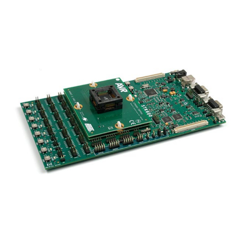
Figure 1: The DA14585/586 ProDev Kit Motherboard .......................................................................... 6
Figure 2: DA14585/586 Daughterboard ................................................................................................ 7
Figure 3: DA14585/586 Jumper Settings .............................................................................................. 7
Figure 4: Jumper J5 Layout................................................................................................................... 8
Figure 5: DA14585/586 Board Layout................................................................................................... 8
Figure 6: Windows Driver Installation.................................................................................................. 10
Figure 7: Device Manager Ports.......................................................................................................... 10
Figure 8: Start Tera Term.................................................................................................................... 11
Figure 9: Setting Up the Port and Testing Connectivity via Tera Term............................................... 12
Figure 10: SmartSnippets Studio Install Link ...................................................................................... 13
Figure 11: Automatically Install J-Link................................................................................................. 14
Figure 12: Select SmartSnippets™ Studio Install Directory................................................................ 14
Figure 13: Keil Lite version.................................................................................................................. 15
Figure 14: CMSIS Package Installation successful............................................................................. 16
Figure 15: CMSIS Package Installation Successful............................................................................ 16
Figure 16: Blinky Project directory....................................................................................................... 17
Figure 17: Blinky Project Keil Workspace ........................................................................................... 18
Figure 18: Blinky Project Options........................................................................................................ 18
Figure 19: Blinky Project Scatter File .................................................................................................. 19
Figure 20: Blinky Project: Debug Option............................................................................................. 19
Figure 21: Blinky Project: Jlink setup .................................................................................................. 20
Figure 22: Blinky Project: Project Building .......................................................................................... 20
Figure 23: Blinky Project: Start Debug Session .................................................................................. 21
Figure 24: Keil Lite Pop Up Window.................................................................................................... 21
Figure 25: Blinky Project: Code Execution.......................................................................................... 21
Figure 26: Blinky Project: Blinky message on COM28 terminal.......................................................... 22
Figure 27: J5 Jumper setting for SPI flash programming.................................................................... 22
Figure 28: Barebone BLE Project directory......................................................................................... 23
Figure 29: Barebone BLE: KEIL Project Layout.................................................................................. 23
Figure 30: Barebone BLE: Interacting with BLE Application............................................................... 24
Figure 31: Hardware Settings for Pro Development Kit ...................................................................... 26
Figure 32: FTDI Latency Timer ........................................................................................................... 27
Figure 33: Reset Circuitry to Dismount R84........................................................................................ 27
Figure 34: R84 Location...................................................................................................................... 28
Figure 35: DA14585/586 QFN40 Daughterboard (321-10-x).............................................................. 28
2 Tables
Table 1: Parameters for Connecting to UART..................................................................................... 11
Table 2: Blinky Example UART and LED Jumper Configuration ........................................................ 25
Table 3: Blinky Example SWD Debugger Jumper Configuration........................................................ 25
Table 4: Revision History..................................................................................................................... 29
Table 5: Status Definitions................................................................................................................... 29


