Kemper Champion C 1200 User manual

Maschinenfabrik KEMPER GmbH & Co. KG D-48694 Stadtlohn, Germany
Postfach 1352 Telephone: +49 (0) 2563 /88-0
E-mail: Info@Kemper-Stadtlohn.de
Internet: www.kemper-stadtlohn.de
Harvesting maize with perfect technology
Operating Manual
Issue B0509
English
No. 93 940
Champion C 1200
MOUNTED UNIVERSAL
FORAGE HARVESTER

Claims arising from
design Kempers policy is one of contineous development and improvement and we therefore
reserve the right to alter design and specifications without notice.
Telephone National Sales Management +49 (0) 25 63 - 88 33
Sales, Machinery +49 (0) 25 63 - 88 34
Shipping Status +49 (0) 25 63 - 88 35
Sales, Spare Parts +49 (0) 25 63 - 88 36 / 88 37
Customer Service +49 (0) 25 63 - 88 26 / 88 32 / 88 84
Fax - National Sales Management +49 (0) 25 63 - 88 155
Sales, Machinery +49 (0) 25 63 - 88 98
Sales, Spare Parts +49 (0) 25 63 - 88 95
Customer Service +49 (0) 25 63 - 88 147
Telefon - International Sales Management +49 (0) 25 63 - 88 152
Sales Machinery +49 (0) 25 63 - 88 22 / 88 25 / 88 28
Sales Spare Parts +49 (0) 25 63 - 88 22 / 88 25 / 88 28
Customer Service +49 (0) 25 63 - 88 26 / 88 32 / 88 84
Fax - International Sales Management +49 (0) 25 63 - 88 155
Sales Machinery +49 (0) 25 63 - 88 44
Sales Spare Parts +49 (0) 25 63 - 88 44
Customer Service +49 (0) 25 63 - 88 147
Telefon National +
International Product Information +49 (0) 25 63 - 88 151
Fax National +
International Product Information +49 (0) 25 63 - 88 155

Table of contents C1200
Operating Manual
Issue B0509
English
No. 81640
Chapter
1.0 Safety instructions
5.0 Product liability
6.0 Introduction – Scope of application
7.0 Standard model
8.0 Special equipment
9.0 Technical data
12.0 Champion harvesting technology
19.0 Technical instructions
22.0 Installation of ejection chute
23.0 Basic settings of mounted forage harvester
24.0 Attachment options
25.0 Working with the forage harvester
26.0 Reversing of drum rotation in the event of blockage
30.0 Operating instructions
32.0 Grinding of blades
32.1 Inspection and adjustment of counter-edge
Blade wheel
Smooth roller
32.2 Design and components of blade wheel
33.0 Replacement of cracker plate
34.0 Maintenance
Lubrication schedule
Tightening torques of screws
38.0 Maintenance and inspection
40.0 Electric circuit diagram
44.0 Troubleshooting
46.0 Spare parts

1 Safety instructions C 1200
Safety and accident prevention regulations
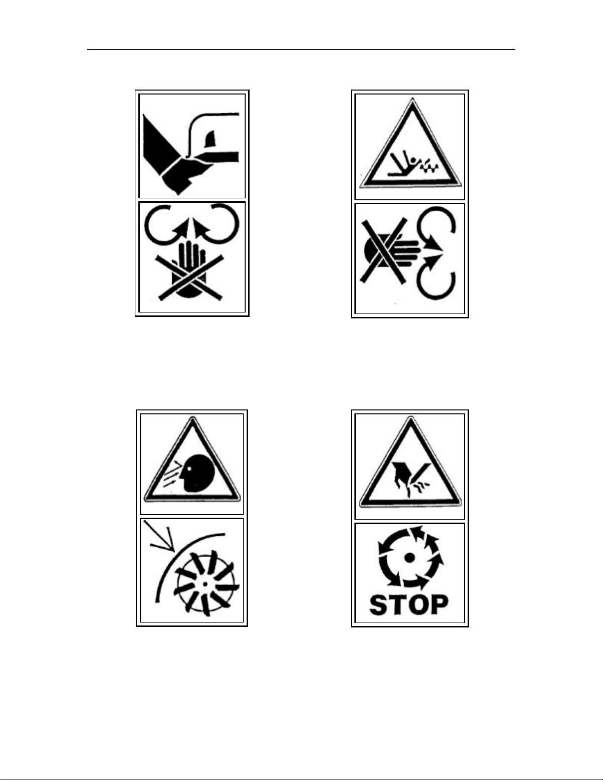
1. Do not allow anyone to stay in the intake area of the machine.
2. The sharpening device may only be operated with the housing of the flywheel cutting disc closed. When
operating the mechanism, stand at the side of the machine. Use protecting spectacles.
3. Never attempt to feed the crop into the machine with your hands or feet.
4. Whenever working on the forage harvester, switch off the PTO and stop the tractor engine.
5. Before traveling on public roads always fold the guard frame over the stalk lifter.
6. Never open the housing of the flywheel cutting disc while the machine is running. DANGER! The cutting disc
will continue to rotate even if the machine is switched off.
7. Make certain the cutting knives are all tightened firmly.
8. Always connect the PTO shaft coupler with care.
9. Keep the PTO shaft guards in good condition and prevent the guard tubes from rotating by attaching the
provided safety chains.
10. Never cut rings from the guard cones of the PTO shaft.
11. Before carrying out any work under the machine, same has to proposed safely.
12. When traveling on public roads the discharge chute has to be positioned in such a way that is does not project
beyond the tractor or the implement, neither to the side nor to the rear.
13. Always comply with the lightening regulations in force of your country.
14. Do not allow anyone to stay in the slewing range of the discharge chute while cutting disc is rotating.
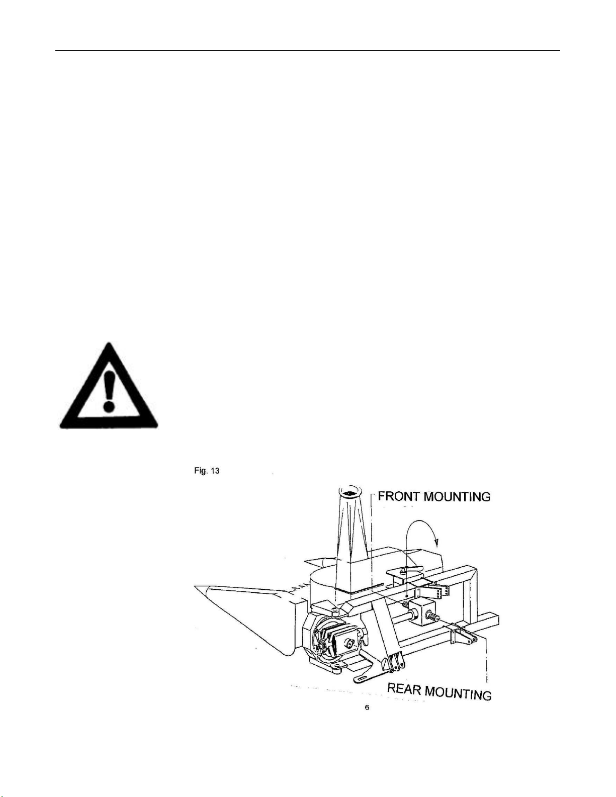
15. Front attachments may only be uncoupled on a level area.
16. Relieve all pressures before disconnecting hydraulic lines. Report immediately to a doctor in case of injury by
hydraulic oil forced out under high pressure.
17. The use of an appropriate ear protection is recommended.
18. Before tracing a foreign object, switch off all drive mechanisms, stop the engine and wait for all moving parts
to stop.
19. The machine height must not exceed 4.3m to avoid touching power lines.
20. The hitch is not designed for supported any additional load.
21. All controls of the machine must be positioned on the tractor mudguard within the operator’s reach.
22. It may be necessary to install front ballast weights to ensure adequate steering capabilities of the tractor.
When installing ballast weights, do not exceed the permissible axle load.
23. Do not allow anyone to stay in the slewing range of the machine. Check that the machine id in a horizontal
position when swinging round. Failure to do so may cause the machine to swing round due to its weights
when the locking mechanism is released. Special care should be taken when operating on a slope.
24. The hydraulic system is under high pressure. All damages or deteriorated hoses have to be replaced
immediately. In any case the hoses and hydraulic lines have to be replaces every six years.
25. Do not exceed the permissible hydraulic pressure of 210 bar.
26. Use only genuine KEMPER spare parts.

1 Safety instructions C 1200
Carefully read the Operator’s Manual
before handling the machine. Shut off engine and remove key before
performing maintenance or repair work
max.
1000
rpm
Hydraulik Druck
Hydraulic pressure of
Pression Hydraulique de
Hydraulische Druck
max.
2 1 0 bar

1 Safety instructions C 1200
Danger by turning cutting rotor. Keep
distance. Keep hands away from rotating crop
dividers.
Put safety shields in place when grinding
knives. Wear safety glasses. Wait until all machine components have
completely stopped before touching them.

1 Safety instructions C 1200
Stay clear of rotating drive line to avoid
personal injury. Read the users manual. Avoid fluid escape under pressure.
Change hoses immediately.
AAdjust the flywheel only with safety gloves
BGrind the knives with safety glasses
CClose grinder sheet immediately after the
flywheel has stopped turning

5Product Liability C 1200
Dear customer
You have made a good choice. We are pleased to congratulate you on you
selection of a KEMPER machine. As your partner we offer quality and perfor-
mance, together with reliable service.
In order to be able to evaluate the conditions of use of our agricultural machi-
nes, and to take these requirements into consideration in the development of
new units, we ask you to provide some information.
This also allows us to inform you selectively of new developments.
Product Liability
and Customer
Information
Product liability instructs manufacturers and dealers to hand over the
instruction manual with each machine and to give the customer practical
instruction on operation, safety and maintenance.
A multiple form (A,B,C) similar to the one illustrated below is supplied with
each Operator's Manual. Confirmation is required that the customer has taken
possession of the machine and the Operator's Manual.
For this purpose, send the signed document A to Kemper. Document B is
retained by the dealer who supplied the machine. Document C is retained by
the customer. At the same time you will be assured that warranty is given.
EC
Certificate of
Conformity
This product has been submitted to the CE test and has obtained the CE
approval mark in conformity with EC Directive 2006/42/EG.
(Communauté europeenne / European Community). An EC Certificate of
Conformity is supplied with this manual. This certificate must be handed over
to the final owner of the machine together with the Operator's Manual.
Handing over the
Operator's
Manual
Attention! Even if the machine is sold at a later date by the customer, the
Operator's Manual must be handed over to the new owner.
This symbol will be found wherever safety advice is given in the manual.
Anyone operating this machine must be given all necessary safety instructions.

6 Introduction –Scope of application C 1200
1. Introduction
In addition to a comprehensive technical description, this manual contains
general and specific explanations concerning function and correct operation of
the CHAMPION and tips how to eliminate malfunctions.
Our policy is one of continuous development and improvement in line with the
latest scientific and industrial knowledge and the company therefore reserves
the right to alter specifications without prior notice.
Directional indications such as “right”and “left”are to interpreted when facing
in direction to travel.
Note the identification numbers of the machine on the last page of this manual.
This information will enable your dealer to send you quickly the correct spare
parts.
2. Operation in accordance with specifications
The Universal Precision Forage Harvester CHAMPION from KEMPER is built
solely for harvesting silage maize or other crops.
In conformity with the relevant regulations the CHAMPION may only be
operated in accordance with specifications. Otherwise no warranty will be
assumed for resulting damage. Observation of the operation maintenance
instructions specified by the manufacturer and exclusive use of genuine
KEMPER spare parts shall also be taken to be a part of operation in
accordance to specifications.

7 Standard Equipment C 1200
Mounting facility
The special drive system allows three mounting options with the same basic machine:
FRONT MOUNTING –REAR MOUNTING –SIDE MOUNTING
The machine can be hitched to any tractor with cat. II 3-pt hydraulics.
Power transmission
Main PTO drive shaft with friction clutch and freewheel mechanism.
Tractors PTO speed: 1000 rpm.
Divided drive system composed of two pivoted elements: one element has two angle gears for
FRONT and REAR mounting, the other is composed of a maintenancefree powerband belt drive.
Cutting unit
New row-independent cutting system composed of a fast rotating cutting rotor. The crop is cut over the
entire working width (1.25 m) by enclosed rotary cutting blades composed of replaceable segments.
Chopping unit
Centrally adjustable flywheel (1180 rpm) fitted with 12 chopping blades with tungsten carbide coating
and special profile for extremely efficient chopping; reversible shear blade with carbide tipped edges;
built-in blade sharpener; flywheel housing fitted with replaceable wear and tear plates; rasp concave
for more efficient re-chopping, useable instead of the smooth concave.
Feeding unit
It is composed of two feed rollers with toothed bars, one springloaded precompression roller and one
smooth roller for efficient crop compression before the flywheel. The feed and precompression rollers
are driven by an oil-bath gearbox. The unit is fitted with an overload protection.
Discharge chute
Foldable discharge chute with hydraulic slewing (140 W);
electrically adjustable discharge double flap;
one double acting control valve required on the tractor.
Chop lengths
Adjustable by changing the V-belt pulleys and by changing the number of blades.
V-belt pulley Number of knlves
W12 6 4
180 mm 5 10 20
210 mm 7.5 15 30

8 Optional Equipment C 1200
Cutting lengths
V-belt pulley WCutting knives
12 6
1 = 153 mm 65975 4 8
1= 218 mm 65977 8.5 17

9 Technical Data C 1200
Technical Data
Length m: 2.80
Width m: 1.76
Height in working position m: 3.95
Weight kg: 1100
Pto speed rpm: 1000
Power requirement kW/HP: min.: 50/70; max.: 110/150
Row interval cm: row-independent
Working width m: 1.25
Chopped lengths mm: 5 –7.5 –10 –15 –20 –30
Mounting facility
The CHAMPION C 1200 can be operated by conventional tractors and by system
tractors as well. Hitch options are the combined REAR and SIDE MOUNTING and
FRONT MOUNTING. The new drive system allows any of these three options to be used
by swinging the divided transmission system into the desired position.
Equipment required on the tractor
1. Max. 110 kW (150 HP). A higher use of power will void guarantee.
2. 12 V connector
3. one double acting steering valve
4. 1000 rpm PTO
5. Standard PTO connection 1 3/8”–6 No. 40496
Optional PTO connection 1 3/8”–21 No. 59025
Optional PTO connection 1 3/4”–6 No. 63254
Optional PTO connection 1 3/4”–21 No. 63255
PTO
The main PTO shaft W 2400 is equipped wit ha slip clutch FK 96/4 (M = 1350 Nm). The
REAR and SIDE mounting versions have a clockwise free run and th e FRONT version
is equipped with an anti clockwise free running clutch.
Optional equipment –Chapter 8
A. Height adjustable rh support wheel (PN 64305), recommended for light tractors
and when SIDE MOUNTING is selected.
B. Height adjustable lh support wheel (PN 68040), recommended for FRONT
MOUNTING in combination with the rh support wheel
C. Stalk lifter, movable in height (PN 63036), for down crops
D. Fixed stalk lifter tips for down crops (PN 69195), 2 Pcs. per set
E. Mechanically driven stalk divider (PN 65960)
F. Additional discharge chute extension (1 m) (PN 64652)
G. V-belt pulleys for 4 mm chop length (PN 65975 & 65977)

10 Designation of assembly groups C 1200

10 Designation of assembly groups C 1200
1. Two-piece discharge flap
2. 12 V electromotor for two-piece flap
3. Foldable discharge chute
4. Hydr. turntable (140°) chute
5. Hydr. connection for double spool valve
6. 12 Volt plug
7. Readjustable disc wheel 1180 rpm
12 chopping knives with wolfram layer
8. Sharpening mechanism
9. Smooth roller
10. Precompression roller with spring tension
11. Intake roller right
12. Intake roller left
13. Intake drum
14. Intake drum bearing
15. Cutting rotor –1.25 m
16. Stalk lifter right
17. Middle prongs
18. Stalk lifter left
19. PTO shaft W 2400
20. Connection (serie 1 3/8”) for 1000 rpm PTO 150 HP
21. Slip clutch K 92/4 –T 1350 Nm
22. 3 point hitch Cat. II adjustable
23. Top link Cat. II adjustable
24. Angle gear 1 with FRONT and REAR connection
25. Angle gear 2 in swiveldrive
26. 3 point hitch frame
27. Hitch (not for heavy weights)
28. PTO shaft between the gear cases
29. V-belt power with free running clutch
30. Angle drive on flywheel cutting disc
31. Changeable V-belt disc for chop length adjustment
32. Changeable V-belt disc for chop length adjustment
33. Automatic overload clutch
34. Locking pin
35. Double side usable shear bar
36. Stripper for smooth roller
37. Precompression roller housing
38. Gearing 4
39. Tension spring for precompression roller 10
40. Changeable crushing plate
41. Crusher plate for refining
42. Support wheel SR 13 = optional
43. Fixed stalk lifter tips for down crops

12 Champion harvesting technology C 1200

12 Champion harvesting technology C 1200
Champion chopping technique
Principle functions of the Champion (Fig. 19)
The patented cutting system of the Champion allows the stalks of the crops to be cut in any direction –
in a lengthwise, transverse or oblique sense to the rows. None of the stalks can escape the area of the
rotary cutter. Once but by the fast rotating blades (9) which are working without any stationary blade,
the stalks are fed by the slow rotating drum (1) along the intake bars (110) and seized by the row of
teeth (111). As a result of the rotation of the gathering drum the crop is pushed along the feed teeth
(11) and transferred along the guides and scrapers and bushed lengthwise to the prepress rollers of
the chopper.
Higher yields through narrow spacing
Methods of cultivation
Alternative methods of corn cultivation are not only more and more discussed, but also already
practiced by institutions and farmers: higher yields are achieved by increasing the number of plants
per surface unit. The new technique allows the existing seed drill to be used, but has only became
possible with the introduction of the row-independent Champion cutting system,.
Ideal distribution of the plants in the field (Fig. 20)
Principle of the new method: The usual row spacing of 75 cm id reduced to 30 cm. With equal seed
density (10 plants per m²), this involves an increased plant spacing in the row.
Higher yields
The new method gives the following advantages:
•The individual plants are more conveniently positioned.
•Faster shading of the soil as a result of the smaller row spacing.
•Prevention of erosion.
•Better utilization of the nitrogen contained in the soil.
•Yields increase by approx. 12 to 17 %.
•Higher quality.

19 Technical instructions C 1200

19 Technical instructions C 1200
Steering capability Sufficient steering capability is only ensured if at least 20 % of the total
weights are acting onto the tractor front axle.
Hitch The hitch is not designed for supporting any additional load. Please
also observe the corresponding decal placed on the machine.
NOTE:
1. It is not permissible to hitch a two-wheeled trailer to a rear
mounted machine.
2. A four-wheel trailer may be attached if the following conditions
are fulfilled:
a) Maximum forward speed: 25 km/h
b) The trailer is fitted with an overrunning brake or with a
brake system which can be operated by the tractor driver
c) The permissible total weight of the trailer is not superior
to the permissible total weight of the tractor x 1.25, but at
most 5 tons.
Overload protection in the
spur gear drive of the
precompression rollers
(Fig. 30)
The friction clutch of the PTO drive shaft protects the drive system and
flywheel against overload. Any overload in the feed mechanism will
activate the pin type safety clutch fitted to the spur gear lubricated with
rolling bearing grease Gresalit LZ 2.
The torque of the clutch is preset. The housing is welded so that the
clutch cannot get loose and the torque settings cannot be modified.
Should it nevertheless be necessary to remove the clutch you should
note that the cup springs 180 are pre-tensioned and circlip 120 can only
be removed if this tension is released.

19 Technical instructions C 1200

19 Technical instructions C 1200
Overload clutch of the
feed drum
(Fig. 30 A)
Another overload clutch is fitted to the feed drum. This clutch is only
operative with the power band set to the correct tension when spring 12
is so adjusted that the measurement 270 mm is given.
Main PTO drive shaft
(Fig 31) Specifications of the PTO drive shaft: size 2400, tubes S4LH/S5,
friction clutch FK 96/4 with freewheel mechanism, independent of the
sense of rotation, clutch torque 1350 Nm, clevis 1 3/8, 6 splines, with
lock pin (tractor side). Clevis size for another tractor PTO’s:
1 3/8 –21 splines = PN 59025
1 3/4 –6 splines = PN 63254
1 3/4 –20 splines = PN 63255
The PTO drive shaft has to be adapted to the tractor to be used.
Minimum overlap of the shaft tubes = 150 mm.
Sense of rotation of the
PTO drive shaft For REAR and SIDE MOUNTING the PTO drive shaft is fitted with a cw
free running clutch:
Cpl. PTO drive shaft = PN 68950
½ PTO drive shaft with free running clutch = PN 69254
For FRONT MOUNTING the PTO drive shaft is fitted with a ccw
rotating free running clutch:
Cpl. PTO drive shaft = 68951
½ PTO drive shaft with freewheel running mechanism: PN 69255
Friction clutch of the main PTO drive shaft –Fig 32
Overload protection The friction clutch in the main PTO drive shaft protects the whole
machine from overload. It is therefore INDISPENDABLE to check the
function of this clutch periodically.
Torque setting The clutch torque is set to 1350 Nm. To maintain this setting it is
essential to perform the maintenance jobs described in the following
two sections.Warranty will be voided if this advise is not observed.
Simple check To be carried out before the first use of the machine and after long
periods of storage:
•Tighten the nuts (2) to relieve the friction discs of load. Rotate
the clutch.
•Unscrew the nuts (2) up to the end of the threaded position.
Detailed check To be carried out at every start of season:
•Tighten the nuts (2) to relieve the friction discs of load.
•To maintain the torque setting (=1350 Nm) proceed as follows:
Mark position of adjusting ring 11 in relation to the clutch
housing. Then remove the adjusting ring.
•Remove cup springs, pressure discs, driving discs and hub.
Clean these components or replace them if necessary.
New slip pads After the installation of new slip pads, the clutch will only reach the full
torque after a running-in period.
•Engage the Champion slowly, avoid any unnecessary load of
the clutch
•The full capacity of the machine should only be utilized after a
running-in period.
Table of contents
Other Kemper Farm Equipment manuals

Kemper
Kemper 490plus User manual

Kemper
Kemper 330 Series User manual

Kemper
Kemper 400F Support Wheel User manual

Kemper
Kemper 460plus User manual

Kemper
Kemper 460 User manual

Kemper
Kemper 475plus User manual

Kemper
Kemper 460plus User manual

Kemper
Kemper 345plus User manual

Kemper
Kemper Pickup N3003 User manual

Kemper
Kemper Pickup C3003 User manual
Popular Farm Equipment manuals by other brands

Truma
Truma Mover XT L Operating instructions & installation instructions

turbocut
turbocut Blitz Kerner Translated Operating Instructions

Claas
Claas LEXION 600 Repair Manual Supplement

PBZ
PBZ CropCare LGX25-1 owner's manual

GSi
GSi Cumberland PNEG-1333 Installation and owner's manual

Bale Band-It
Bale Band-It GFC 100 Operator's manual