Digi ConnectCore 6UL SBC Pro Quick user guide

ConnectCore 6UL
SBC Pro
Hardware Reference Manual

Revision history—90001531
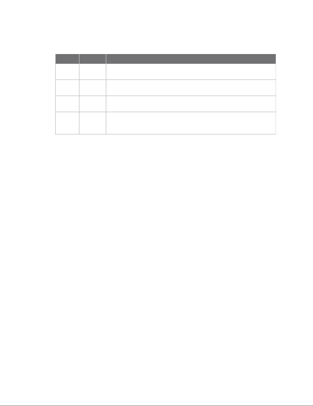
Revision Date Description
1P November
2016
Initial release
A May 2017 Add antenna section, I/O Expander section, additional power interfaces,
power consumption data, and pinout comments
B June 2017 Modify regulatory and certification information as required by RED (Radio
Equipment Directive)
C July 2017 Update I2C interface table, add known issue re: LCD interface wake-up
when connecting Fusion 7" display, add RGB values to parallel display
interface chart
Trademarks and copyright
Digi, Digi International, and the Digi logo are trademarks or registered trademarks in the United
States and other countries worldwide. All other trademarks mentioned in this document are the
property of their respective owners.
© 2017 Digi International Inc. All rights reserved.
Disclaimers
Information in this document is subject to change without notice and does not represent a
commitment on the part of Digi International. Digi provides this document “as is,” without warranty of
any kind, expressed or implied, including, but not limited to, the implied warranties of fitness or
merchantability for a particular purpose. Digi may make improvements and/or changes in this manual
or in the product(s) and/or the program(s) described in this manual at any time.
Warranty
To view product warranty information, go to the following website:
www.digi.com/howtobuy/terms
Send comments
Documentation feedback: To provide feedback on this document, send your comments to
techcomm@digi.com.
Customer support
Digi Technical Support: Digi offers multiple technical support plans and service packages to help our
customers get the most out of their Digi product. For information on Technical Support plans and
pricing, contact us at +1 952.912.3444 or visit us at www.digi.com/support.
Support portal login: www.digi.com/support/eservice
ConnectCore 6UL SBC Pro Hardware Reference Manual 2

Contents
About the ConnectCore 6UL SBC Pro
Overview 5
Features and functionality 5
Block diagram 7
Placement 8
Top view 8
Bottom view 9
Connectors 10
Top view 10
Bottom view 11
Part numbers 11
ConnectCore 6UL SBC Pro interfaces
Power interfaces 15
DC-in jack connector 15
Additional power connector 15
Coin cell connector 15
Power and reset buttons 15
5V supply connector 16
3.3V supply connector 16
System boot interfaces 16
Boot configuration 16
Boot mode 17
Debug interfaces 18
JTAG 18
SWD 18
Console port 19
Communication interfaces 19
NFC NTAG 19
10/100 Mbps Ethernet 20
Antenna connector 21
USB Host 21
USB OTG 22
Mini PCI Expressslot 23
Micro-SIM 25
XBee 26
Multimedia interfaces 27
Parallel display 27
LVDS 29
ConnectCore 6UL SBC Pro Hardware Reference Manual 3

ConnectCore 6UL SBC Pro Hardware Reference Manual 4
Parallel camera 30
Audio 31
Storage interfaces 33
microSD 33
eMMC 33
Additional expansion interfaces 34
I/O Expander 34
CAN 37
I2C 38
SPI 39
GPIO 40
UART 41
User interfaces 42
User LED 42
ConnectCore 6UL SBC Pro specifications
Electrical specification 44
Supply voltages 44
Power consumption 44
Use case descriptions 44
Mechanical specification 45
Top view 46
Bottom view 47
Profile view 47
Environmental specification 47
WLAN specification 48
Known issues
Known issue: Connecting Fusion 7" display causes system to wake from suspend mode 50
Affected versions/models 50
Description 50
Workaround/fix 51
Regulatory information
Maximum power and frequency specifications 53
Europe 53
Declarations of Conformity 53
CE mark 53

About the ConnectCore 6UL SBC Pro
Overview
The ConnectCore 6UL SBC Pro, formerly known as the ConnectCore 6UL SBC, is an ultra compact
Pico-ITX board featuring the Digi ConnectCore 6UL system-on-module that integrates an NXP i.MX6UL
application processor, DDR3 memory, NAND flash memory, WLAN/Bluetooth, power management IC
for optimized power consumption applications, and a microcontroller assistant (MCA) for supporting
additional functionality. This stand-alone product serves as the reference design for the ConnectCore
6UL system-on-module and can also be used on its own to accelerate time to market.
Features and functionality
lConnectCore 6UL module
oi.MX6UL single ARM Cortex-A7 core operating at speeds up to 528 MHz
o16-bit DDR3-800 memory interface with a density up to 1 GB (default: 256 MB)
o8-bit SLCNAND flash with density up to 2 GB (default: 256 MB)
oIEEE 802.11 a/b/g/n/ac WLAN and Bluetooth 4.2 dual mode
lPower:
oPower jack or industrial-dedicated 5V power connector
oCoin-cell battery charger, supplying the on-module RTC
oPower and reset buttons
lBoot source configuration: NAND, USB
lDebug:
oStandard IEEE 1149.1 JTAG interface
oSingle Wired Debug (SWD) interface for the microcontroller assistant (MCA) and the I/O
expander
oTTL serial console
lMultimedia:
oParallel 24-bit LCD interface with FFC on-board connector
oLVDS interface with up to four differential data pairs
o8-bit parallel camera interface
ConnectCore 6UL SBC Pro Hardware Reference Manual 5

About the ConnectCore 6UL SBC Pro Features and functionality
ConnectCore 6UL SBC Pro Hardware Reference Manual 6
oAudio CODEC with a stereo headphone jack and expansion connectors for speakers, line-
in, mic-in, and line-out lines
lStorage:
oNAND flash
omicroSD card slot
o4 GBytes eMMC
lCommunication:
oTwo 10/100MbpsEthernet interface
oTwo USB Host 2.0 interfaces through a stacked USB A type connector
oUSB OTG with micro AB USB connector
oSISO IEEE 802.11 a/b/g/n/ac +Bluetooth 4.2 dual mode with on-board U.FL or external
MMCX antenna connector
oPCI Express Mini Card slot supporting full and half-size cards
o2 KBytes NFCNTAG
lExpansion:
oUSB Host 2.0 port
oCAN connector with two FlexCAN interfaces including transceivers
oUART connector with one TTL level UART and two RS-232 UART ports
oSPI
oAudio connector with MIC, LINE-IN, and LINE-OUT
oAudio connector with speakers and LINE-IN
oGPIO connector with analog input for touch and digital GPIO signals
oI2C
lUser interface:
oOne user LED
lI/O expander: to allow advanced power-management functionality over the carrier board
lDimensions:
oPico-ITX form factor, 10 cm x 7.2 cm
oPCB height 2 mm
oMaximum part height:
nTOP side: 15.6 mm (USB connector)
nBOTTOM side: 6.8 mm (PCIe connector) (Host PCBs must have a cutout to
accommodate the components on the bottom side of the module.)

About the ConnectCore 6UL SBC Pro Block diagram
ConnectCore 6UL SBC Pro Hardware Reference Manual 7
Block diagram

About the ConnectCore 6UL SBC Pro Placement
ConnectCore 6UL SBC Pro Hardware Reference Manual 8
Placement
Top view

About the ConnectCore 6UL SBC Pro Placement
ConnectCore 6UL SBC Pro Hardware Reference Manual 9
Bottom view

About the ConnectCore 6UL SBC Pro Connectors
ConnectCore 6UL SBC Pro Hardware Reference Manual 10
Connectors
Top view

About the ConnectCore 6UL SBC Pro Connectors
ConnectCore 6UL SBC Pro Hardware Reference Manual 11
Bottom view
Part numbers
The following table lists manufacturers and part numbers for each connector.
Connector Interface Manufacturer
Manufacturer part
number
J1 5V power-in jack SHOGYO MJ-179LR
J2 Coin cell Molex 53047-0210
J3 Power and reset Molex 53047-0310
J4 3.3V output Molex 53047-0210
J5 5V output Molex 53047-0210
J6 Ethernet 1 Xmultiple XMG-9799-8821-100D-
L1TO-H-HIM
J7 microSD Molex 500873-0806

About the ConnectCore 6UL SBC Pro Connectors
ConnectCore 6UL SBC Pro Hardware Reference Manual 12
Connector Interface Manufacturer
Manufacturer part
number
J8 Ethernet 2 Xmultiple XMG-9799-8821-100D-
L1TO-H-HIM
J9 Console Molex 53047-0410
J10 Boot mode Samtec TSW-102-07-G-S
J12 Mini PCIe Foxconn AS0B226-S68Q-7H
J14 Micro SIM Molex 78727-0001
J15 USB Host KYCON KUSBX-AS2N
J16 USB OTG KYCON KMMX-ABSMT5SG-30TR
J17 Parallel camera OMRON XF2M-2015-1A
J18 Antenna Amphenol 908-22101
J21 Parallel display OMRON XF2M-4015-1A
J22 Audio jack CUI Inc. SJ1-3515-SMT
J23-J24 XBee module Samtec SMM-110-02-F-S-P-TR
J25 XBee expansion Molex 53047-0310
J26 Audio expansion - line in, line out, and
microphone
Molex 53047-0810
J27 CAN expansion Molex 53047-0610
J28 I2C expansion Molex 53047-0610
J29 UART expansion Molex 53047-1410
J30 GPIO expansion Molex 53047-1410
J31 LVDS Hirose DF14A-20P-1.25H
J32 USB expansion Molex 53047-0610
J33 Audio expansion - speaker and line in Molex 53047-0610
J34 SPI expansion Molex 53047-0810
J35 5V power in TE
Connectivity
640456-2
J36 NFC NTAG Molex 53047-0210
SW1 Power button ITT KSC221JLFS
SW2 Reset button ITT KSC221JLFS

About the ConnectCore 6UL SBC Pro Connectors
ConnectCore 6UL SBC Pro Hardware Reference Manual 13
Connector Interface Manufacturer
Manufacturer part
number
SW4 RF kill & RF antenna internal/external
selection switch
C&K
Components
TDA02H0SB1
CAD1 i.MX6UL JTAG Tag Connect - -
CAD2 MCA SWD Tag Connect - -
CAD3 IO expander SWD Tag Connect - -

ConnectCore 6UL SBC Pro interfaces Power interfaces
ConnectCore 6UL SBC Pro Hardware Reference Manual 15
Power interfaces
DC-in jack connector
A 5V DC-in power jack connector provides power to the entire ConnectCore 6UL SBC Pro system. An
overvoltage circuit protects the SBC from voltages higher than 6.5V (up to 12V). Behind the
overvoltage protection, a 5V load switch (U7) controls the power delivered to the SBC. The enable pin
of the power switch is controlled through PWR_EN/IO14 signal of the I/O expander. A green LED on
the top of the board lights up when the 5V output of the load switch is enabled.
Additional power connector
In addition to the power jack assembled on the SBC Pro, a 2-pin, 2.54 mm pitch, latched vertical
connector on the top side of the PCB offers an alternative power rail to the whole system. This power
input is also protected against overvoltage events.
The following table shows the pinout of the power connector (J35):
Pin Signal name Description
1 VIN 5V power supply rail
2 GND Ground
Coin cell connector
A 2-pin, 1.25 mm pitch straight connector provides battery charging functionality and powers the real-
time-clock (RTC) interface when the main supply is off. The main power supply rail powers the RTC
while it is connected. You can supply the RTC with a primary Lithium cell (non-rechargeable), a
secondary Lithium cell (rechargeable), or a supercap.
Note For more information about the coin cell, see Electrical specification.
The following table shows the pinout of the coin cell connector (J2):
Pin Signal name Description
1 VCC_LICELL Power supply for RTC
2 GND Ground
Power and reset buttons
The power button (SW1) on the ConnectCore 6UL SBC Pro is connected to the on-module MCA, which
provides the following functionality:
Board status Power button action Response
OFF Short press Power on
ON or SLEEP Long press for 5 seconds Power off

ConnectCore 6UL SBC Pro interfaces System boot interfaces
ConnectCore 6UL SBC Pro Hardware Reference Manual 16
Board status Power button action Response
SLEEP Short press Wake-up
ON Short press Sleep
The ConnectCore 6UL SBC Proalso has a "Reset" button (SW2), which resets the ConnectCore
6ULmodule.
Note You can configure the duration of some power button actions. See the device tree bindings for
the MCA power key driver for more information.
5V supply connector
The ConnectCore 6UL SBCPro provides a 2-pin, 1.25 mm pitch straight connector with a regulated 5V
supply for powering external circuitry. The 5V supply is generated on the on-board 5V regulator, which
is also used internally in the ConnectCore 6UL SBC for powering interfaces such as the displays (LCD
and LVDS) and the USB VBUS. The following table shows the pinout of the 5V supply connector (J5).
Pin Signal name Description
1 5V 5V power line
2 GND
3.3V supply connector
The ConnectCore 6UL SBCPro provides a 2-pin, 1.25 mm pitch straight connector with a regulated
3.3V supply for powering external circuitry. The 3.3V supply is generated on a buck regulator of the
ConnectCore 6UL PMIC (3V3_EXT power domain), which is also used on-board for powering many
interfaces of the ConnectCore 6UL SBC carrier board. The following table shows the pinout of the 3.3V
supply connector (J4).
Pin Signal name Description
1 3V3 3.3V power line
2 GND
System boot interfaces
Boot configuration
The ConnectCore 6UL SBC Pro has several 10 Kresistors to allow for maximum flexibility when setting
up the boot source configuration of the ConnectCore 6UL module. The following table provides
detailed information about resistor configuration.
Note Default configuration is shown in bold.

ConnectCore 6UL SBC Pro interfaces System boot interfaces
ConnectCore 6UL SBC Pro Hardware Reference Manual 17
BOOT_CFG bit (pad)
Resistor configuration
Pull-up Pull-down
BOOT_CFG1[0] (LCD_DATA0) R222 R112
BOOT_CFG1[1] (LCD_DATA1) R233 R113
BOOT_CFG1[2] (LCD_DATA2) R234 R147
BOOT_CFG1[3] (LCD_DATA3) R235 R153
BOOT_CFG1[4] (LCD_DATA4) R17 R238
BOOT_CFG1[5] (LCD_DATA5) R236 R156
BOOT_CFG1[6] (LCD_DATA6) R237 R166
BOOT_CFG1[7] (LCD_DATA7) R100 R239
BOOTSTRAP NAND
BOOT_CFG1[0] Row address cycles:
00 - 3 cycles
01 - 2 cycles
10 - 4 cycles
11 - 5 cycles
BOOT_CFG1[1]
BOOT_CFG1[2] Number of devices:
00 - 1 device
01 - 2 devices
10 - 4 devices
11 - Reserved
BOOT_CFG1[3]
BOOT_CFG1[4] Pages in block:
00 - 128 pages
01 - 64 pages
10 - 32 pages
11 - 256 pages
BOOT_CFG1[5]
BOOT_CFG1[6] Samsung toggle mode DDR NAND:
0 - Raw NAND
1 - Toggle mode NAND
BOOT_CFG1[7] Boot device selection:
1 - Boot from NAND interface
Note Boostrap pins are protected against being overwritten by devices connected to the LCD signals.
See the ConnectCore 6UL SBC Pro schematics (PDF) for circuitry around U30 and U31.
Boot mode
By default, the ConnectCore 6UL module boots from the internal board settings, allowing it to boot
from internal NAND memory. However, it is possible to boot from USB through a jumper(J10). This
jumper forces the i.MX6UL to boot from the source programmed in the one-time-programmable (OTP)

ConnectCore 6UL SBC Pro interfaces Debug interfaces
ConnectCore 6UL SBC Pro Hardware Reference Manual 18
bits. If the boot configuration OTP bits are not programmed, the CPU falls back to booting into USB
debug mode.
The default state for the jumper is open, which configures the i.MX6UL to boot from board settings
(from NAND flash). If the NAND flash doesn't contain valid firmware, the i.MX6UL also falls back to
booting into USB debug mode. You can use this functionality for recovery purposes, such as if the boot
loader is erased or cannot boot.
For advanced functionality, the ConnectCore 6UL SBC Pro provides four resistors to configure the
SOM boot mode. For more information about boot mode configuration, please refer to the
ConnectCore for i.MX6UL system-on-module Hardware Reference Manual.
The following table shows resistor configuration for the different boot modes:
R24 R25 R28 R29 Comment
Not populated Not populated Populated Populated Boot from fuses
Populated Not populated Not populated Populated Boot from serial downloader
Not populated Populated Populated Not populated Boot from board settings (default)
Populated Populated Not populated Not populated Reserved
Note A different resistor configuration may prevent the ConnectCore 6UL module from booting.
Debug interfaces
JTAG
The ConnectCore 6UL SBC Pro provides a Tag Connect footprint for accessing the i.MX6UL JTAG debug
port. You can find this footprint on the bottom side of the board.
SWD
The ConnectCore 6UL SBC Pro provides two options for programming and debugging the MCA of the
ConnectCore 6UL module. The first option is a 2x5, 1.27 mm pitch pin header on the top side of the
board (which, by default, is not populated). The following table shows the pinout of the SWD connector.
Pin Signal name Description
1 VCC_MCA 3.3V supply voltage of the MCA
2 MCA_SWD_DIO SWD bidirectional data pin
3 GND Ground
4 MCA_SWD_CLK SWD clock signal
5 VCC_MCA 3.3V supply voltage of the MCA
6 NC Not connected
7 NC Not connected

ConnectCore 6UL SBC Pro interfaces Communication interfaces
ConnectCore 6UL SBC Pro Hardware Reference Manual 19
Pin Signal name Description
8 NC Not connected
9 GND Ground
10 MCA_RESET_N Reset signal for MCA
The second option is the Tag Connect footprint on the bottom side of the board.
You can also access the SWD interface of the I/O expander using options similar to those found on the
on-module MCA: a non-populated 2x5, 1.27 mm pitch pin header and a Tag Connect footprint.
Console port
The ConnectCore 6UL SBC Pro provides a 4-pin, 1.25 pitch connector for the debug console port. The
UART5 port of the ConnectCore 6UL module is used as the console port. The console signal is a serial
TTL, which travels through the console connector directly to the i.MX6UL processor. You can use a TTL-
to-USB cable to access this console port from a host PC USB port. The following table shows the
pinout of the console connector (J9):
Pin Signal name Description
1 UART5_TX Transmission line
2 UART5_RX Receiver line
3 3V3 3.3V power line
4 GND Ground
CAUTION! Pin 3 - 3V3 is a power output of the SBC. It should not be connected to a
power input coming from the USB to TTL cable, for instance.
Console default settings:
Baud rate 115200
Data 8 bit
Parity none
Stop 1 bit
Flow control none
Communication interfaces
NFC NTAG
A 2KB (2016 bytes of EEPROM and 64 bytes of SRAM) NTAG is carried by the ConnectCore 6UL SBC
Pro. This NTAG is an energy-harvesting NFC Forum type 2 Tag with field detection and I2C interface.

ConnectCore 6UL SBC Pro interfaces Communication interfaces
ConnectCore 6UL SBC Pro Hardware Reference Manual 20
The RF interface is based on the ISO/IEC 14443 Type A standard. This RF interface is passive and must
be supplied by an RF field.
The SBC has an antenna connector (36) for the NTAG:
Pin Signal name Description
1 LA Antenna connection LA
2 LB Antenna connection LB
Note For more information on this interface, please contact Digi technical support at
www.digi.com/support.
10/100 Mbps Ethernet
The ConnectCore 6UL SBC Pro provides two 10Base-T/100Base-Tx Ethernet interfaces using two
Microchip LAN8720Ai 10/100 Ethernet PHYs. The Ethernet PHYs are connected to the i.MX6UL ENET1
and ENET2 instances, respectively. Both Ethernet interfaces are accessible through RJ-45 connectors
with integrated link/activity LEDs. The following table shows the pinout of both RJ45 connectors.
Pin Signal name Description
1 TD+ Transmit pair data (+)
2 TD- Transmit pair data (-)
3 RD+ Receive pair data (+)
4 CT Center tap
5 CT Center tap
6 RD- Receive pair data (-)
7 NC Not connected
8 GND Ground
9 LED1_P Green LED anode
10 LED1_N Green LED cathode
11 LED2_P Yellow LED anode
12 LED2_N Yellow LED cathode
The 10/100 EthernetPHYs have two outputs to indicate the link and activity status of the port. These
outputs are connected to two LEDs that are integrated with the Ethernet connectors. The following
table shows the link/activity status indicated by the two LEDs:
Green LED Yellow LED Link/activity status
OFF OFF Link OFF
Table of contents
Other Digi Motherboard manuals

Digi
Digi NET+50 User manual

Digi
Digi NS9750 User manual

Digi
Digi XBee Grove Development Board Series User manual

Digi
Digi ConnectCore 6 SBC Quick user guide

Digi
Digi ConnectCore 6 Quick user guide

Digi
Digi ConnectCore 8M Nano Quick user guide

Digi
Digi ConnectCore MP13 Quick user guide

Digi
Digi ConnectCore 9U User manual

Digi
Digi XBee Grove User manual

Digi
Digi ConnectCore 8M Mini Quick user guide
Popular Motherboard manuals by other brands

IEI Technology
IEI Technology WAFER-LX2-800 user manual

Xtool
Xtool X100 PAD2 user manual

Honeywell
Honeywell IDENT-KEY 3 Mounting and Connection Instructions

Gigabyte
Gigabyte AMD Socket AM2 Processor Motherboard... user manual

JETWAY
JETWAY G03-NC94-F Technical manual

Gigabyte
Gigabyte GA-M61PME-S2P user manual