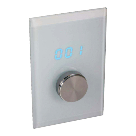
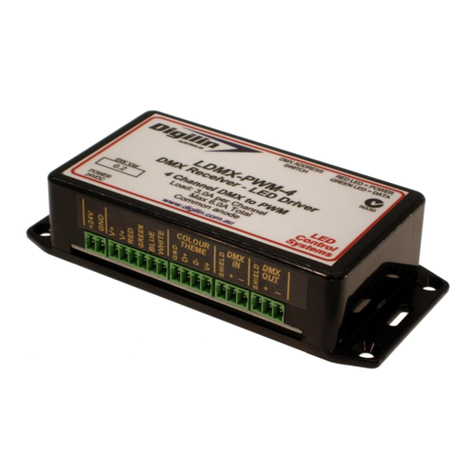
Digilin Colour Touch VW User manual

©2021 Digilin Technologies
Document Rev: 1.0 - 2 June 2021
Product specifications are subject to change without notice.
Colour Touch VW
VW DMX Controller FW 1.0
User Manual

Colour Touch VW - VW DMX Controller FW 1.0
User Manual
1.0 - 2 June 2021
digilin.com.au Page 2 of 11
+617 3899 1267
Table Of Contents
Notes.....................................................................................................................................................................................................................................................................................................2
Introduction.................................................................................................................................................................................................................................................................................. 3
Specifications .............................................................................................................................................................................................................................................................................4
Physical.......................................................................................................................................................................................................................................................................................4
Inputs............................................................................................................................................................................................................................................................................................4
Communications.............................................................................................................................................................................................................................................................4
Installation ......................................................................................................................................................................................................................................................................................5
Wiring...........................................................................................................................................................................................................................................................................................5
Wiring to LDD Controllers...........................................................................................................................................................................................................................5
Mounting .................................................................................................................................................................................................................................................................................5
Operation.........................................................................................................................................................................................................................................................................................6
Software Version ...........................................................................................................................................................................................................................................................6
User Interface.....................................................................................................................................................................................................................................................................6
Dimming....................................................................................................................................................................................................................................................................................6
CCT (Correlated Colour Temperature) .................................................................................................................................................................................................6
Switching Drivers Off/On..................................................................................................................................................................................................................................... 7
Power on State ................................................................................................................................................................................................................................................................ 7
Device Configuration ................................................................................................................................................................................................................................................7
Performing a Factory Reset...............................................................................................................................................................................................................................9
Appendix A. Wiring Diagram with LCTHM Power ....................................................................................................................................................................... 10
Appendix B. Wiring Diagram with AUX Power..................................................................................................................................................................................11
Notes
•Install in a dry sheltered position
•Interior use only
•Ensure adequate ventilation
•Installation should only be performed by a qualified professional
•Install in accordance with all appropriate wiring standards
•Never connect a LED fitting to a driver that is powered. Doing so may result in damage to the LED.
•Always make sure the output voltage range and output current of the LED driver match the
requirements of the LED fitting. Failure to do so may result in damage both the driver and fitting.

Colour Touch VW - VW DMX Controller FW 1.0
User Manual
1.0 - 2 June 2021
digilin.com.au Page 3 of 11
+617 3899 1267
Introduction
The Colour Touch VW Controller is a DMX show generator with a simple and intuitive user interface,
specifically designed for use with Digilin’s LED VariWhite Driver to control installations of tuneable white
LED fittings. Tuneable white fittings allow the user to set the colour temperature through a set range of
values, thus allowing the user to set the mood and ambience of an area by controlling the colour
temperature of the white light.

Colour Touch VW - VW DMX Controller FW 1.0
User Manual
1.0 - 2 June 2021
digilin.com.au Page 4 of 11
+617 3899 1267
Specifications
Physical
U n i t s
Front Plate Dimensions
76 x 116 x 10.6
mm
Protrusion Dimensions (less
cabling)
50 x 75 x 21.9
mm
Protrusion Dimensions (with
RJ45 plug)
50 x 75 x 29
mm
Weight
100
g
Inputs
U n i t s
Voltage
12 -48
VDC
Current @ 24VDC
25
mA
Fuse
100
mA
Communications
U n i t s
DMX Channels
2
DMX Start Address
Adjustable –Default 1
DMX Load
0.25
Standard Devices
Expansion Bay
N/A

Colour Touch VW - VW DMX Controller FW 1.0
User Manual
1.0 - 2 June 2021
digilin.com.au Page 5 of 11
+617 3899 1267
Installation
Wiring
The Colour Touch VW has two inputs, a RJ45 and a screw terminal
block. The RJ45 carries the DMX signal and also can carry power in
for the Colour Touch VW. The screw terminal block the main
power input for the Colour Touch. The pinout for the RJ45
connector can be found in Table 1 Wiring to Cat5 cables.
Wiring to LDD Controllers
Digilin’s newest range of LDD controllers use RJ45 and cat5 cables
for DMX. To connect them to a Colour Touch VW, just use a
straight through CAT5/6 cable with RJ45 plugs on either end. To
apply power to the Colour Touch VW just toggle on the LCTHM
switch on the LDD driver.
T 5 6 8 A
T 5 6 8 B
V+
Blue
Blue
D+
Green/White
Orange/White
D-
Green
Orange
GND
Blue/White, Brown,
Brown/White
Blue/White, Brown,
Brown/White
Table 1 Wiring to Cat5 cables
Mounting
The Colour Touch VW Controller is housed in a standard Clipsal plate, and as such is compatible with any
standard mounting boxes or clips. There is also a mounting frame (Clipsal Part number 4000VH1) available
in 5 colours that can be used to cover the black base and compliment wall colour.
To install the Colour Touch VW Controller
1. Remove the fascia by inserting a small flat blade screwdriver into the slots on the top and bottom
of the plate and lever it off.
2. Mount to wall using appropriate hardware.
3. Re-attach fascia by pushing it into place at the top then at the bottom.
Figure 1 Connections on the Colour Touch Controller

Colour Touch VW - VW DMX Controller FW 1.0
User Manual
1.0 - 2 June 2021
digilin.com.au Page 6 of 11
+617 3899 1267
Operation
Software Version
On power up, the Colour Touch VW Controller will scroll text along the screen. The text will indicate the
software version followed by configuration. For this manual, the software version should be a “ 1 . x ” value
and the type should be “VW”. In the software version is different, please contact Digilin Technologies.
User Interface
The Colour Touch VW uses five touch buttons and a display to navigate menus and light settings. The five
buttons include increase/decrease (up/down), left/right, and on/off(middle). The main menu has two items:
“Dim” for dimming and “Cct” for colour temperature. The menus can be switch at anytime using the left and
right keys. The device will always default back to the dimming menu after screen goes to sleep and when
device is turned on. The flow of the menus can be seen in Figure 2: Menu system.
Figure 2: Menu system
Dimming
Each show on the Colour Touch VW can have a dimming multiplier of 1-100%, this can be controlled via the
“Dim” menu. to access the Dim menu, use the left and right keys until “Dim” is displayed on the Colour
Touch. Then use the up and down arrows to control the level of dimming. 1 = 1% and 100 = 100%
To exit this menu just use the left or right keys.
Note that, depending on the LED driver, dimming may alter the dynamics of Colour Touch VW Controller
shows.
CCT (Correlated Colour Temperature)
The Colour Touch VW can perform colour mixing of the RGB LEDs to create a correlated colour
temperature. This value is displayed in kelvin from 2700K to 6000K. To enter this mode, use the left and right
arrows to scroll to the “Cct” menu. after the correct menu is selected use the up and down arrows to apply
the CCT values to the DMX output. To exit this menu, use the left and right key to change menu.
Note: The default Colour Mixing settings are tuned to Digiln’s RGB strip. Use of other branded LED strip may
produce unexpected results. Also, CCT were calibrated at MAX dim level, lower dim levels may affect the
colour.

Colour Touch VW - VW DMX Controller FW 1.0
User Manual
1.0 - 2 June 2021
digilin.com.au Page 7 of 11
+617 3899 1267
Switching Drivers Off/On
To turn off the LED light fittings, simply tap the centre button for at least 1 second. This will turn off the LED
drivers and pause any running show. To turn back on simply tap the centre button again. This will bring up
the “Dim” menu and resume the current show.
Power on State
Upon applying power to the Colour Touch VW, the controller will apply a snapshot of values to the dim and
CCT. This is known as the power on state. This can be configured in the settings menu. Each setting is
described in Table 2.
S t a t e
M e n u I t e m
f u n c t i o n
Power Off
“off”
DMX output powered off (set to level 0)
Last State
“Las”
Run the last state
User
Defined
Sate
“man”
Run the user defined state
Table 2: Power on states
To program the user defined state, a button sequence must be performed. First set the controllers desired
show. Then hold left and right buttons. While holding left right, hold up and down buttons until the light
sequence flashes. The user defined state is now saved.
(5 seconds)
Device Configuration
The Colour Touch VW device configuration can be configured via the front control panel. These
configuration options include device DMX address, device DMX repeats and the Power on state. The DMX
address can be adjusted from 1 to (512-Footprint) where footprint is the device repeats x 4ch. The device
repeats value control how many times the DMX sequence RGB repeats itself. The power on state can also
be configured. Adjusting these settings will require a reboot to properly apply them.
Enabling the settings menu
To access these configurations options a settings menu needs to be enabled. To enable the settings menu
hold left and right until all button LEDs flash. After the button LEDs flash a new menu item will be
accessible for 10mins. To navigate to the setting menu, use the left and right keys until “Set” appears. To
hide the settings menu before the 10min timeout power cycle the device.
Adjusting the DMX start address
Once the Settings menu is enabled the DMX start address can be adjusted.
1. Navigate to “Set” using left and right arrows
2. Tap down once to “Add”
3. Tap Right once and a values will appear onscreen. This is the current DMX start setting.
4. Use the up and down arrows to edit the DMX start address.
5. To exit tap left back to “Add” sub menu.
6. Then tap up to “set” to access main menu.
Figure 3 shows the settings menu navigation.

Colour Touch VW - VW DMX Controller FW 1.0
User Manual
1.0 - 2 June 2021
digilin.com.au Page 8 of 11
+617 3899 1267
Adjusting the DMX duplicates
The DMX duplicates is the amount of times the VW channels are repeated on the DMX512 output. For
example, a duplicate of three would create this signal sequence VWVWVW.
Once the Settings menu is enabled the DMX duplicates can be adjusted.
1. Navigate to “Set” using left and right arrows
2. Tap down twice to “Dup”
3. Tap Right once and a value will appear onscreen. This is the current DMX Duplicate setting.
4. Use the up and down arrows to edit the DMX duplicate.
5. To exit tap left back to “Dup” sub menu.
6. Then tap up twice to “set” to access main menu.
7. Upon leaving the settings menu the control will save it to memory.
Adjusting the Power on State
The power on state controls what configuration to apply to the Colour Touch VW at power on. once the
setting menus is enabled, the power on state can be adjusted.
1. Navigate to “Set” using left and right arrows.
2. Tap down three times to “Pos”.
3. Tap Right once and a value will appear onscreen. This is the current Power on state setting.
4. Use the up and down arrows to change the setting.
5. To exit tap left back to “Pos” sub menu.
6. Then tap up three times to “set” to access main menu.
7. Upon leaving the settings menu the control will save it to memory.
Figure 3 shows the settings menu navigation.
Figure 3: Settings Menu Navigation

Colour Touch VW - VW DMX Controller FW 1.0
User Manual
1.0 - 2 June 2021
digilin.com.au Page 9 of 11
+617 3899 1267
Performing a Factory Reset
The Colour Touch VW is fitted with a factory reset button on the back of the device. This is only accessible
after the device has been remove from front faceplate and device is on. To perform the factory reset follow
the steps below.
1. Remove Colour Touch VW front face plate using a flat blade screwdriver.
2. Pull Colour Touch VW out exposing the factory reset button situated on the back.
3. While device is powered press and hold the factory reset button for 5 seconds.
4. Reinstall Colour Touch VW back onto plate.
S e t t i n g
V a l u e
DMX Address
1
DMX Duplicates
1
Dim
50
CCT
3500
Power on state
last
Table of contents
Other Digilin Controllers manuals
Popular Controllers manuals by other brands
ZPA Pecky, a.s.
ZPA Pecky, a.s. MODACT MOK 125 Installation and operating instructions
Schaudt
Schaudt LRM 1218 operating instructions

EFI
EFI Fiery X3eTY 50_45C-KM Service guide
Toshiba
Toshiba TS3000 Series instruction manual
National Instruments
National Instruments cRIO-9032 user manual
Keith McMillen Instruments
Keith McMillen Instruments QuNeo Reference manual

Sporlan
Sporlan Superheat Installation and servicing instructions
Honeywell
Honeywell UDC3500 product manual
VISIO
VISIO VD-T user manual
Ashly
Ashly VCM-88C Technical notes & specifications
Emerson
Emerson PeC C100 Hardware Implementation Guidelines
Dialog Semiconductor
Dialog Semiconductor DA9070 user manual


