Digital Barriers EDGEVIS HD-IP150 User manual

ã Copyright 2020 Digital Barriers plc
EDGEVIS HD-IP150
HARDWARE INSTALLATION GUIDE
VERSION 8.0 – NOVEMBER 20
Thank you for purchasing the EdgeVis HD-IP150. This document explains how to physically configure the HD-IP150. As
well as identifying the available connectors and status indicators on the device, it also details how to add your desired
SIM card to it. This document should be read in conjunction with the IP Series, HD-Q800, 4K-R800 - Setup Guide,
which covers the web-based setup interface for all devices in the IP Series range, including the HD-IP150.
EDGEVIS HD-IP150 HARDWARE INSTALLATION GUIDE
ISSUED: 10 NOVEMBER 2020 PAGE 2
Introduction
Before proceeding with the installation and setup of your HD-IP150 unit, please ensure that you check the package
contents listed below, refer to the installation notes on the next page and consult the Quick Start Guide that was
supplied with your unit for step-by-step instructions on preparing hardware and software components.
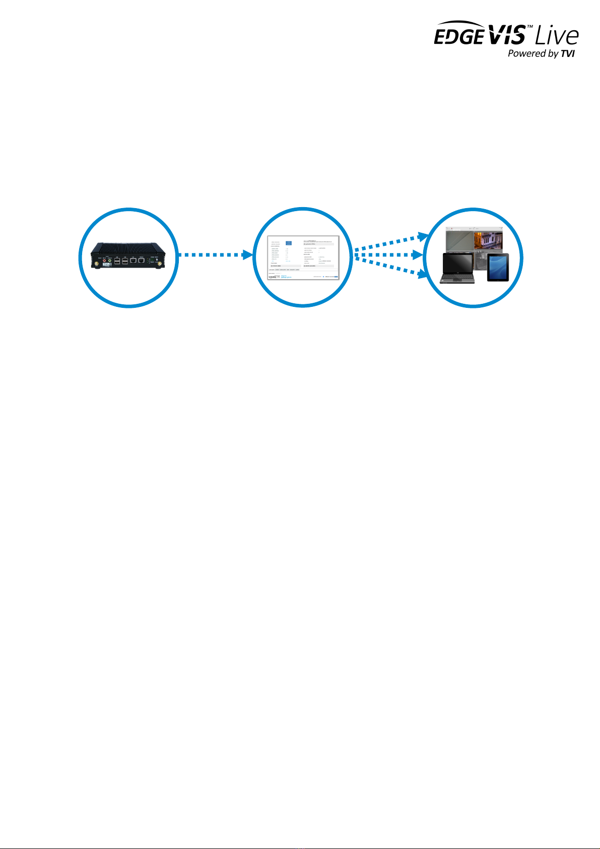
To operate this device you will need to setup, or have access to, the following architecture:
To proceed you must have access to an EdgeVis Server, with an account created for the encoder to use. If you do not
have an EdgeVis Server available refer to EdgeVis Server Setup Guide which will walk through the steps required to
install the server and create the necessary accounts required to proceed.
What is in the box?
EdgeVis encoder EdgeVis HD-IP150
Accessories AC/DC 12V power supply, mains power lead, 2 x 3G/4G antenna, GPS antenna, USB
Wi-Fi adapter
Printed materials Quick Start Guide
How do I configure the HD-IP150 unit?
After the introduction, there are three sections in this document that help you to configure your HD-IP150 unit:
Section 1 Basic operations of the unit
Powering the unit and connecting devices or drives to the HD-IP150
Section 2 Configuring communications on the HD-IP150
Connecting to wired, Wi-Fi and cellular networks (including SIM card insertion)
Section 3 Next steps…
With the HD-IP150 unpacked and wired, what are the steps required to set up the encoder?
Appendix A Troubleshooting and frequently asked questions
Potential hardware issues that may be encountered with an HD-IP150
HD-IP150
EdgeVis Clients
EdgeVis Server
sends video to
sends video to

EDGEVIS HD-IP150 HARDWARE INSTALLATION GUIDE
ISSUED: 10 NOVEMBER 2020 PAGE 3
SAFETY NOTES
The EdgeVis Encoder has been designed for use in indoor environments. It can operate in temperatures from 0˚C to
+55˚C whilst powered from 12V DC.
All deployments of an HD-IP150 encoder unit should ensure that the device is not mounted:
• Within explosive zones
• Within 0.5m of a powered transmitter and/or receiver antenna
• Within the engine bay/compartment of a vehicle
• Within 1m of a vehicle fuel fill point (direct line of sight)
WARNING: The HD-IP150 Encoder has been designed to operate from a 12V DC supply. Do not connect it directly
to mains power outlet. Use the AC/DC adapter supplied with the unit.
The following precautions must be taken to avoid damage to the unit:
• DO NOT CONNECT DIRECTLY TO THE MAINS SUPPLY
• Always ensure the supply is within the specified voltage range and employ
suitable filtering if voltage spikes are likely
• Do not reverse the polarity of the DC power supply. It will cause irreparable
damage to the HD-IP150
• Always provide a common ground between the HD-IP150 unit and all connected
equipment
WARNING: Failure to observe these precautions will invalidate the warranty.

EDGEVIS HD-IP150 HARDWARE INSTALLATION GUIDE
ISSUED: 10 NOVEMBER 2020 PAGE 4
Section 1- Basic operations of the unit
The EdgeVis HD-IP150 is a small and robust device, ideally suited for use in
fixed installations for the recording and live streaming of video from a
single IP camera.
Device connectors
The HD-IP150 features integral TVI streaming using an internal 4G modem, external Wi-Fi adapter or wired LAN, and
archiving onto built-in SSD/HDD. The device supports the connection of one IP camera. Connectors for the HD-IP150
are shown below. Items shown in italics are not currently utilised on the device – but may be supported in future
product releases.
Front Panel Layout
1
MIMO antenna connector
8
LAN1 port (typically for IP camera connection)
2
Power reset switch
9
Status LEDs
3
Microphone input connector
10
Remote power switch connector
4
Audio Line output connector
11
Local power switch
5
USB 3.0 port (recommended for external disk)
12
GPS antenna connector
6
USB 2.0 ports x2. For keyboard, mouse, etc.
13
4G/LTE antenna connector
7
LAN2 port (typically for wired server connection)
1
2
3
4
5
6
7
8
9
10
11
12
13
EDGEVIS HD-IP150 HARDWARE INSTALLATION GUIDE
ISSUED: 10 NOVEMBER 2020 PAGE 5
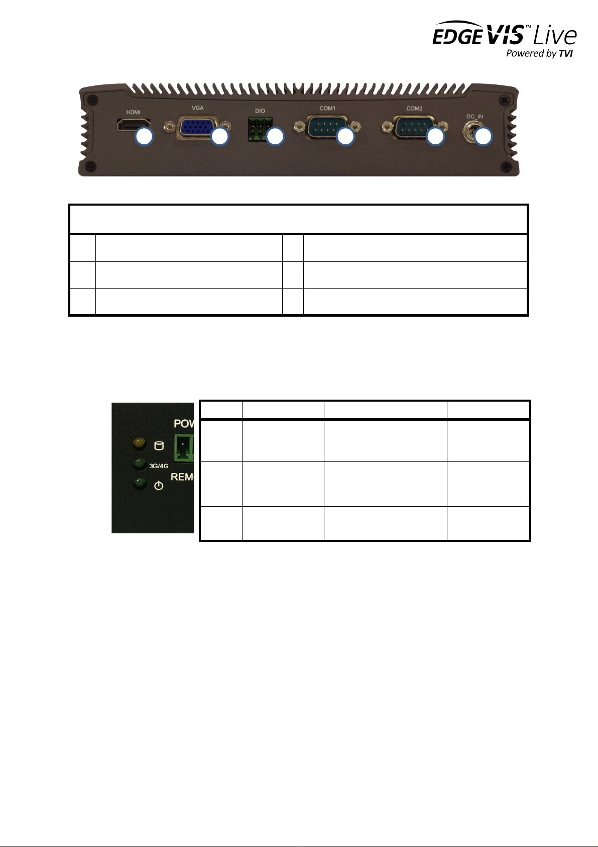
Rear Panel Layout
1
HDMI video connector
4
RS232 port
2
VGA video connector
5
RS232 port
3
Digital I/O connector
6
12V power input connector
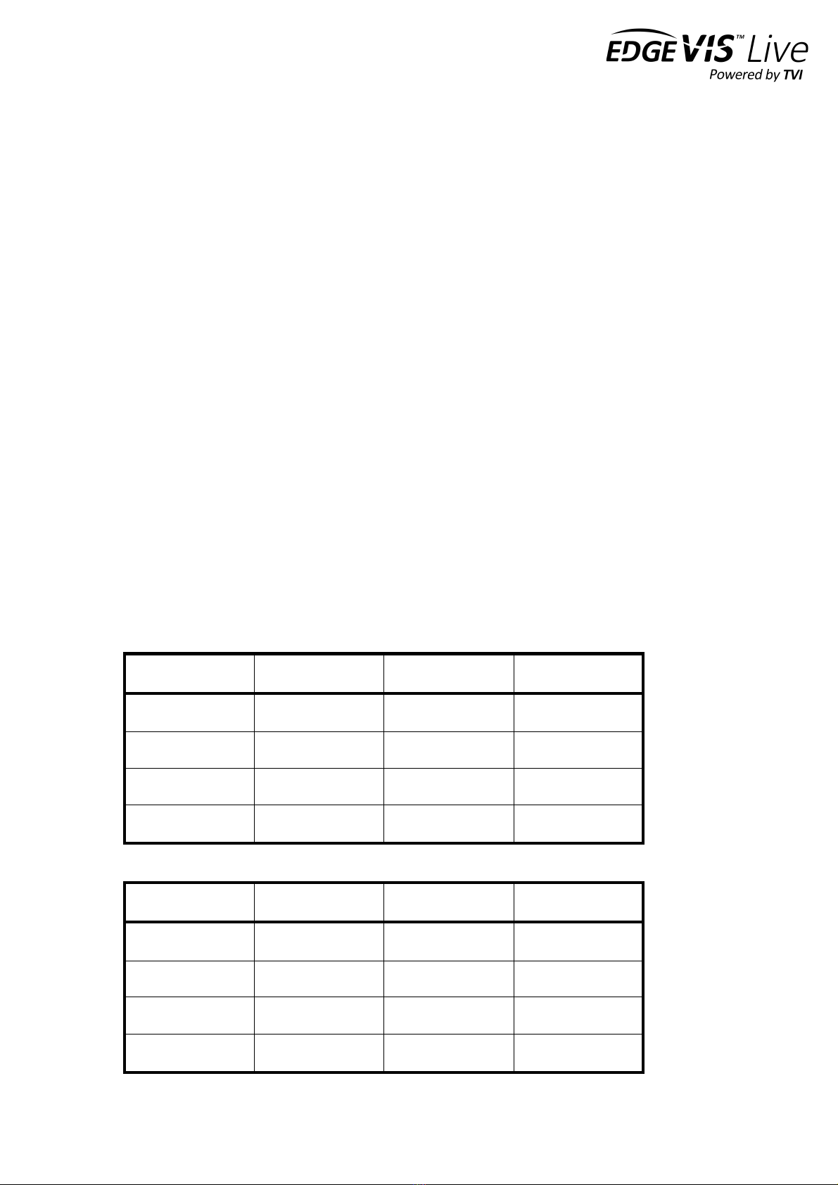
Status indicators
The status LEDs on the top left of the front panel (see 9. in the front panel layout) provides visual feedback on device
status.
Powering the device and switching it on/off
The HD-IP150 must be powered using an AC/DC adapter (supplied). To switch the unit on simply connect the output
cable from the AC/DC adapter to the DC input connector on the back of HD-IP150 and connect the AC/DC adapter to
the mains power outlet. The unit can be remotely powered on/off by using a simple switch connected to the Remote
Power Switch Connector.
Connecting antennas for cellular and GPS connections
The front of the unit also includes antenna connectors for 3G/4G cellular modem and GPS. Antennas for each of these
are supplied with the HD-IP150.
LED
Off
Flashing
On
Storage
HDD/SDD inactive
HDD/SDD reading or writing
N/A
3G/4G
Modem not
powered
Modem powered, connected
and
transferring data
Modem powered
but not
transferring data
Power
System off
N/A
System on
1
2
3
4
5
6

EDGEVIS HD-IP150 HARDWARE INSTALLATION GUIDE
ISSUED: 10 NOVEMBER 2020 PAGE 6
Default LAN port IP Addresses
For ease of deployment each LAN port on the HD-IP150 device is pre-configured with a static IP address:
!
!
Connecting IP cameras
The HD-IP150 allows for connection of two IP cameras via either of the LAN ports located on the front of the unit. Each
camera should be connected to the device using standard Ethernet cable and it should be powered by its own power
supply. Two ports are provided to allow separate connections between the HD-IP150 and the IP Cameras and internet
connection (e.g. an ADSL or SatCom router).
Refer to Section 1 of the IP Series, HD-Q800, 4K-R800 - Setup Guide for details on configuring the Ethernet ports and
IP cameras to work together. The list of specific cameras supported on the IP Series of products can be found on the
Support site: http://tvi-support.digitalbarriers.com
Storage medium
The HD-IP150 supports either an internal solid state disk (SSD) or hard disk drive (HDD). An SSD drive is recommended
for greater reliability, particularly if using the HD-IP150 for vehicle-based applications. The disk can be removed only
when the unit is powered off.
Additionally, it is possible to use external USB disks to store recordings. For further details, refer to Section 2 of the IP
Series, HD-Q800, 4K-R800 - Setup Guide v8.0.
Updating the software on the unit
Once notified of a new software release by Digital Barriers, updates are available for download from the EdgeVis
support site (see below for link) for installation onto the device.
There are three ways to update the firmware:
• To update remotely, upload the new firmware to the Firmware tab within the EdgeVis Server web interface
and then, from the Encoder tab, select Upgrade Firmware from the Select Action menu on the desired
encoder.
• Using the Upgrade Firmware option when logged into the encoder’s local web interface.
• Copy the firmware onto a USB flash drive and insert into a USB port on the front of the unit. The flash drive
can be inserted into a running unit or before the unit is powered up. The update procedure will take
approximately ten seconds, and then the encoder will beep four times. At this point it is safe to remove the
pen and the unit will automatically reboot. If the update fails the encoder will beep continually.
To access or register for the Digital Barriers Support Site, visit tvi-support.digitalbarriers.com
LAN Port
Default IP Address
Subnet mask
LAN1
192.168.10.1
255.255.255.0
LAN2
192.168.11.1
255.255.255.0
USB Ethernet
192.168.12.1
255.255.255.0

EDGEVIS HD-IP150 HARDWARE INSTALLATION GUIDE
ISSUED: 10 NOVEMBER 2020 PAGE 7
Section 2 - Configuring communications on the HD-IP150
The HD-IP150 supports communications over 3G/4G cellular, Wi-Fi and
wired LAN connections. A cellular connection requires the insertion of a
valid SIM card. Each of the communication methods are set up using the
HD-IP150 web-interface Comms Settings page. More detailed
information on HD-IP150 set up can be found in the IP Series Setup Guide.
Connecting over a 3G/4G cellular network
A valid mobile SIM card is required in order to connect the HD-IP150 over a cellular communications bearer. The unit
has an inbuilt modem for 3G/4G connection with a 3G/4G antenna connector on the front of the device. Note: despite
the ultra-efficient bandwidth usage achieved by TVI, the HD-IP150 is considered a heavy data use product on cellular
networks. It is recommended that an unlimited data plan (or if unavailable, a heavy consumption data plan) is set up
with your Mobile Network Service Provider for use with the HD-IP150.
The SIM card holder is located under the cellular modem card. In order to insert/change the SIM card, you must open
the bottom plate of the HD-IP150 unit and remove the cellular modem card to expose the SIM holder. Please ensure
the unit is powered down before attempting this operation. Follow the instructions below to insert a SIM card.
Note it is recommended that when changing the SIM, suitable ESD precautions should be taken to avoid damage to
the HD-IP150.
Step 1
Remove the four fixing screws from the bottom plate of
the unit and retain. Lift the bottom plate to access the
modem card.
Step 2
Remove thermal pad from the modem

EDGEVIS HD-IP150 HARDWARE INSTALLATION GUIDE
ISSUED: 10 NOVEMBER 2020 PAGE 8
Step 3
Remove two screw fixings, lift the card and gently pull it
out from the connector
Step 4
Push the SIM card holder frame in the direction indicated
by an arrow to open the holder.
Step 5
Place the SIM card in to the holder as in the picture above
Step 6
Close the holder and lock it
Step 7
Install the modem, place thermal pad back on to it and
close the unit. Check that the cables connecting the
modem to the front panel have not become loose due to
the movement of the modem.
The HD-IP150 can now be powered up. The network settings (provided by the SIM card Mobile Network Service
Provider) are entered during device setup – details of which are covered in Section 2 of the IP Series Setup Guide.

EDGEVIS HD-IP150 HARDWARE INSTALLATION GUIDE
ISSUED: 10 NOVEMBER 2020 PAGE 9
Connecting over a Wi-Fi network
The HD-IP150 supports Wi-Fi communication through the use of an external USB Wi-Fi Dongle (supplied). Please refer
to Appendix A of the IP Series, HD-Q800, 4K-R800 - Setup Guide for a list of supported devices.
Plugging a compatible dongle into the HD-IP150 before powering the unit will make Wi-Fi available as a comms bearer
within the IP Series web configuration interface.
Connecting over a wired LAN connection
When using a wired LAN connection as the communications bearer, connect an Ethernet cable into the LAN connector
on the front of the HD-IP150. Details for the LAN connection must be entered during the device setup – details of
which are covered in Section 1 of the IP Series Setup Guide.

EDGEVIS HD-IP150 HARDWARE INSTALLATION GUIDE
ISSUED: 10 NOVEMBER 2020 PAGE 10
Section 3 – Next Steps…
After unpacking the encoder, inserting a SIM card, and wiring up your
encoder the next step is to perform the initial setup, where comms
settings, server details and IP Cameras are configured.
Setting up the encoder
With the encoder unpacked and all of the physical setup complete it is time to set up the encoder so that it is available
on the EdgeVis Server for viewing. Refer to the IP Series, HD-Q800, 4K-R800 - Setup Guide for further details.
EDGEVIS HD-IP150 HARDWARE INSTALLATION GUIDE
ISSUED: 10 NOVEMBER 2020 PAGE 11
Appendix A - Troubleshooting and frequently asked
questions
How many channels does the HD-IP150 support?
The HD-IP150 can record up to two cameras, and transmit one of those cameras.
What level of recording and streaming performance is achievable?
Based on the processing power of the HD-IP150, the unit can typically achieve 25/30 fps of 1080p quality recording
whilst simultaneously streaming one 1080p quality video at 10 fps.
What recording functions does the HD-IP150 support?
The HD-IP150 can be set up to record continuously, or to record on an alarm trigger. Recordings can be set to
overwrite old recordings automatically, or to stop on full.
What indicative recording times and streaming rates are achievable?
The HD-IP150 records the incoming video stream from each IP camera without modification. The options set (e.g.
frame-rate, bandwidth) when configuring the IP camera will directly affect the recording time. Below are the
approximate recording times for two cameras and various storage options when the IP cameras are set to typical
settings:
Frame rate
IP Camera b/w
480GB SSD
960Gb SDD
1 fps
1.4 Mbps
16 days
32 days
6.25 fps
3 Mbps
8 days
16 days
12.5 fps
5 Mbps
4 days
8 days
25 fps
7 Mbps
3 days
6 days
Below are the approximate recording times for two SD cameras:
Frame rate
IP Camera b/w
480GB SSD
960Gb SDD
1 fps
100Kbps
200 days
100 days
6.25 fps
250 Kbps
80 days
40 days
12.5 fps
500 Kbps
40 days
20 days
25 fps
1 Mbps
20 days
10 days

EDGEVIS HD-IP150 HARDWARE INSTALLATION GUIDE
ISSUED: 10 NOVEMBER 2020 PAGE 12
What bearers can the HD-IP150 use to transmit video to EdgeVis Server?
The HD-IP150 includes an inbuilt 4G/LTE cellular modem for efficient streaming over commercially available cellular
networks. It can also transmit using its inbuilt LAN port or optional Wi-Fi module. EdgeVis optimises its transmission
to the characteristics of the bearer that it is being used to maximise performance.
How does EdgeVis Server licensing work in relation to the HD-IP150?
The EdgeVis Server licensing model is based on the number of cameras connected to the encoder. An HD-IP150 unit
therefore requires up to two encoder licences for licensing purposes (if two cameras are being utilised). These licences
must either be of type EdgeVis Lite, Enhanced or Enterprise, depending on the feature set desired.
Which IP cameras are supported by the HD-IP150?
The list of specific cameras supported on the IP Series of products can be found on the Support site:
http://tvi-support.digitalbarriers.com.

EDGEVIS HD-IP150 HARDWARE INSTALLATION GUIDE
ISSUED: 10 NOVEMBER 2020 PAGE 13
Appendix B - External Device Dimensions
198mm
144.8mm
42mm
6mm

EDGEVIS HD-IP150 HARDWARE INSTALLATION GUIDE
ISSUED: 10 NOVEMBER 2020 PAGE 14
FCC COMPLIANCE
This equipment has been tested and found to comply with the limits of a Class B digital device, pursuant to Part 15 of the FCC Rules. These limits are designed
to provide reasonable protection against harmful interference in a residential installation. This equipment generates, uses and can radiate radio frequency
energy and, if not installed and used in accordance with instructions, may cause harmful interference to radio communications. If this equipment does cause
harmful interference to radio or television reception, which can be determined by turning the equipment off and on, the user is encouraged to try to correct
the interference by one or more of the following:
• Reorient or relocate the receiving antenna
• Increase the separation between the equipment and receiver
• Connect the equipment to an outlet on a circuit different from that to which the receiver is connected
The EdgeVis HD-IP150 unit contains a radio module that has been FCC Approved for fixed and mobile applications (FCC ID: RI7UC864G).
The radio module conforms to the following US Directives;
• Use of RF Spectrum. Standards: FCC 47 Part 22
• Use of RF Spectrum. Standards: FCC 47 Part 24
• EMC (Electromagnetic Compatibility). Standards: FCC47 Part 15
The EdgeVis HD-IP150 Encoder contains a radio module that has been FCC Approved for fixed and mobile applications (FCC ID: ZCN722MV1).
The radio module conforms to the following US Directive;
• Use of RF Spectrum. Standards: FCC 15 Part C.
FCC Warning: changes or modifications not expressly approved by the party responsible for compliance could void the user's authority to operate the
equipment.
To meet the FCC’s RF exposure rules and regulations:
• The use of a non-shielded interface cable with the EdgeVis HD-IP150 Encoder device is prohibited
• The power cord must be 3m (10 feet) or less in length and a ferrite should be fitted within 5cm (2 inches) of the equipment
• The antenna(s) used with the EdgeVis HD-IP150 unit must be installed to provide a separation distance of at least 20cm (8 inches) from all persons
and must not be co-located or operating in conjunction with any other antenna or transmitter
• The antenna(s) used with the EdgeVis HD-IP150 unit must not exceed 3dBi
The EdgeVis HD-IP150 unit shall only be used for fixed and mobile applications.
CE COMPLIANCE STATEMENT
The EdgeVis HD-IP150 Encoder complies with the following European Union Directives:
• Low Voltage Directive 2006/95/EEC for product safety
• Directive 89/336/EEC for EMC conformity
The EdgeVis HD-IP150 Encoder contains a radio module that has been approved for integration into fixed and mobile applications. The radio&module
conforms to the following European Union Directives:
• R&TTE Directive 99/05/EC (Radio Equipment & Telecommunications Terminal Equipment)
• Low Voltage Directive 73/23/EEC for product safety
• Directive 89/336/EEC for EMC conformity
In order to satisfy the essential requisite of the R&TTE 99/05/EC directive, the radio module is compliant with the following standards:
• Radio Spectrum, Standard: EN 301 511, EN 301 908-1 and EN 301 908-2
• EMC (Electromagnetic Compatibility). Standards: EN 301 489-1, EN 301 489-7 and EN 301 489-24
• LVD (Low Voltage Directive) Standards: EN 60950-1:2001+A11:2004
The use of this product may be dangerous and has to be avoided in the following areas:
• Where it can interfere with other electronic devices in environments such as hospitals, airports, aircraft, etc.
• Where there is risk of explosion such as gasoline stations, oil refineries, etc.
The user must ensure that:
• The antenna(s) used with the EdgeVis HD-IP150 unit must be installed to provide a separation distance of at least 20cm from all persons and must
not be co-located or operating in conjunction with any other antenna or transmitter
• The antenna(s) used with the EdgeVis HD-IP150 unit must conform to the requirements stated in the installation guide
• The EdgeVis HD-IP150 unit shall only be used for fixed and mobile applications
It is responsibility of the user to enforce the country regulations and specific environment regulations.
Table of contents
Other Digital Barriers Media Converter manuals


Popular Media Converter manuals by other brands


H&B
H&B TX-100 Installation and instruction manual

Bolin Technology
Bolin Technology D Series user manual

IFM Electronic
IFM Electronic Efector 400 RN30 Series Device manual

GRASS VALLEY
GRASS VALLEY KUDOSPRO ULC2000 user manual

Linear Technology
Linear Technology DC1523A Demo Manual

Lika
Lika ROTAPULS I28 Series quick start guide

Weidmuller
Weidmuller IE-MC-VL Series Hardware installation guide

Optical Systems Design
Optical Systems Design OSD2139 Series Operator's manual

Tema Telecomunicazioni
Tema Telecomunicazioni AD615/S product manual

KTI Networks
KTI Networks KGC-352 Series installation guide

Gira
Gira 0588 Series operating instructions

Lika
Lika SFA-5000-FD user guide