Digital Barriers EDGEVIS HD-R700 Manual

EDGEVIS HD-R700
HARDWARE INSTALLATION GUIDE
VERSION 7.1 – FEBRUARY 18
Thank you for purchasing the EdgeVis HD-R700. This document explains how to configure the HD-R700, as well as
identifying the available connectors and status indicators on the encoder.

EDGEVIS HD-R700 HARDWARE INSTALLATION GUIDE
ISSUED: 9 FEBRUARY 2018 PAGE 2
Introduction
Before proceeding with the installation and setup of your HD-R700 encoder, please ensure that you check the package
contents listed below, refer to the installation notes on the next page and consult the Quick Start Guide that was
supplied with your encoder for step-by-step instructions on preparing hardware and software components.
To operate this encoder you will need to set up, or have access to, the following architecture:
To proceed you must have access to an EdgeVis Server, with an account created for the encoder to use. If you do not
have an EdgeVis Server available refer to EdgeVis Server Quick Start Guide which will walk through the steps
required to install the server and create the necessary accounts required to proceed.
What is in the box?
EdgeVis encoder EdgeVis HD-R700
Accessories AC/DC, low power 12V/65W power supply, mains power cord, cellular and Wi-Fi
antennas, USB configuration pen.
Printed materials Quick Start Guide
How do I configure the HD-R700 encoder?
Following the introduction, there are three sections in this document that help you to configure your HD-R700
encoder:
Section 1 Basic operations of the encoder
Powering the encoder and connecting cameras or peripherals to the HD-R700
Section 2 Initial encoder configuration
Encoders require details of the desired communications settings and server account details
Section 3 Next steps…
With the HD-R700 configured and connected to the server, what should be done next?
Appendix A Frequently asked questions
Potential hardware issues that may be encountered with an HD-R700
Appendix B Connecting a PC to the HD-R700
Instructions on how to configure a PC to connect to the HD-R700
Appendix C Technical specifications and connectors
A full break-down of the encoder’s specifications, dimensions and connectors
HD-R700
EdgeVis Clients
EdgeVis Server
sends video to
sends video to

EDGEVIS HD-R700 HARDWARE INSTALLATION GUIDE
ISSUED: 9 FEBRUARY 2018 PAGE 3
SAFETY NOTES
The EdgeVis HD-R700 encoder has been designed for use in indoor and outdoor environments. It can operate in temperatures
from -20˚C to +60˚C whilst powered from a DC power supply in the range of 9-36V.
All deployments of an HD-R700 encoder should ensure that the encoder is not mounted:
• Within explosive zones
• Within 0.5m of a powered transmitter and/or receiver antenna
• Within the engine bay/compartment of a vehicle
• Within 1m of a vehicle fuel fill point (direct line of sight)
WARNING: The HD-R700 Encoder has been designed to operate from a DC supply in the range of 9-36V DC. Do
not connect it directly to mains power outlet. Use the AC/DC adapter supplied with the encoder.
The following precautions must be taken to avoid damage to the encoder:
• DO NOT CONNECT DIRECTLY TO THE MAINS SUPPLY
• Always ensure the supply is within the specified voltage range and employ
suitable filtering if voltage spikes are likely
• Do not reverse the polarity of the DC power supply. It will cause irreparable
damage to the HD-R700
• Always provide a common ground between the HD-R700 encoder and all
connected equipment
WARNING: Failure to observe these precautions will invalidate the warranty.
Handling:
• The encoder is capable of operating at +60˚C ambient temperatures. In such
deployments the enclosure temperature may become too hot to touch.
Precautions should always be taken when handling the unit.

EDGEVIS HD-R700 HARDWARE INSTALLATION GUIDE
ISSUED: 9 FEBRUARY 2018 PAGE 4
Section 1- Basic operations of the encoder
The EdgeVis HD-R700 includes connections to support real-time video
streaming (including PTZ control), edge-based recording (using built-in or
external devices), trigger-based operation and communications over a
range of bearers. This section covers operations and connectivity for
supported operating modes.
Encoder connectors
All of the connections for the HD-R700 are accessed on the front and back plates of the encoder.
Front Panel Layout
1
Local Wi-Fi
Antenna
5
Remote Wi-Fi Antenna
2
Local Ethernet
Connector
6
System USB
for updates and
configuration
3
MIMO Antenna
7
Cellular SIM Card
4
Audio Connector
8
Storage USB
Back Panel Layout
9
Remote Ethernet
Port
14
Alarms / IO
10
Cellular Antenna
15
DC In (9-36V)
5A Max on each pin,
10A Max combined
11
SD Camera 1
Power, PTZ,
Tamper and video
16
HD-SDI
Video Signal
Connector
12
SD Camera 2
Power, PTZ,
Tamper and video
17
HD Camera –
Power, PTZ and
Tamper
13
Status Dongle Port
18
RDC Port
connects to external
ground sensor
EDGEVIS HD-R700 HARDWARE INSTALLATION GUIDE
ISSUED: 9 FEBRUARY 2018 PAGE 5
Powering the encoder and switching it on/off
To switch the encoder on simply connect the output cable from the AC/DC adapter (or appropriate battery) to the DC
input connector on the back of HD-R700 and connect the AC/DC adapter to the mains power outlet. Unplug the cable
from the DC input connector to switch off the encoder.
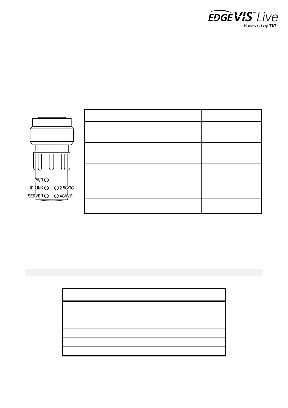
LED Status Dongle – using the optional status dongle
If the LED status dongle is available, plug it into the port marked “Status / IO”. The LEDs on the status dongle provide
visual feedback of the encoder’s current status:
LED
Off
Flashing
On
Power
System off
Long (2s off): PSU/temperature
issue.
Short (1s off): Programmed sleep.
System on
IP-Link
-
Orange: Initialising connection
Green: Connecting to cellular
Red: Problem on connection
Green: connected to network
Red: problem with SIM
Server
-
Orange: connecting to Server
Green: hand-shake with Server
Red: Server connection rejected
Green: connected to Server
Red: unable to connect to
Server
2.5G/3G
-
-
Orange: using 2.5G
Green: using 3G
4G/WI-FI
-
-
Orange: using 4G
Green: using Wi-Fi
Refer to Monitoring Encoder Status for further information on the expected LED behaviour, and trouble-shooting
advice for error conditions.
Monitoring encoder status
Regardless of which configuration option is chosen, once the desired options are entered the encoder will attempt to
connect to EdgeVis Server.
Note - If the encoder is being configured for cellular operation, ensure that the SIM card is inserted into the SIM slot.
Power-on the encoder and then, if available, monitor the sequence of the LED status dongle, which should be:
Sequence
LED & Colour
Indicates
1
Flashing orange IP-Link
Initialising connection
2
Flashing green IP-Link
Connecting to network (cellular only)
3
Solid green IP-Link
Connection successfully created
4
Flashing orange Server-Link
Connecting to Server
5
Flashing green Server-Link
Handshaking with Server
6
Solid green Server-Link
Successfully connected to server
Users who are logged into the web setup interface can also monitor encoder status from the Configuration area's
home page.

EDGEVIS HD-R700 HARDWARE INSTALLATION GUIDE
ISSUED: 9 FEBRUARY 2018 PAGE 6
Using the LEDs to troubleshoot issues
The following table describes some of the common problems that may occur:
LED Status
Problem with...
Possible error conditions
No LEDs ON
Power
• Encoder is not plugged in or switched on
• There is a problem with the power supply
Power (green) ON
No other lights
Initialising the encoder
• Possible problem with encoder hardware
• Corrupt firmware
Power (green) flashing
No other lights
Not a problem. Unit is
sleeping.
Power (green) blinks
every 2 seconds
No other lights
Environment.
• Voltage supplied to the unit is outside 9V … 36V. Check battery or
PSU supplying the unit.
• Internal temperature is outside the operating range. Allow the unit to
return to an acceptable temperature.
IP-Link LED solid red
SIM card
• SIM card not detectable
IP-Link LED
flashing red
Creating network
connection
• The network cable is not plugged in
• The router is not powered
• The network settings are incorrect
• The encoder is not getting a DHCP address
• Incorrect mobile settings
• Incorrect Wi-Fi settings
Server-Link LED
solid red
Unable to connect
to server
• The server is not running
• The server address is incorrect
• There is a firewall blocking access to the Internet
• The encryption pack is incorrect
Server-Link LED
flashing red
Server rejected
connection
• The supplied encoder password is incorrect
• There is an existing encoder with the same name on the server
Using the Deployment Confidence Checker
The Deployment Confidence Checker is used to deploy the unit in situations where any illumination, e.g. visible LEDs,
is undesirable.
With the HD-R700 powered, pressing the button will signal the encoder to generate a buzzer sequence within the
button casing.
Buzzer response
Meaning
Long buzz -> Pause -> Short buzz -> Short buzz
Encoder is connected to server
Long buzz
Attempting to connect
Long buzz -> Pause -> Long buzz
Error condition

EDGEVIS HD-R700 HARDWARE INSTALLATION GUIDE
ISSUED: 9 FEBRUARY 2018 PAGE 7
Default LAN port IP Addresses
For ease of access to the local web setup interface, and ONVIF video output, the HD-R700 encoder’s local Ethernet
port is pre-configured with a static IP address:
!
Connecting HD-SDI and composite cameras
The HD-R700 supports connection of a single HD-SDI digital video camera and two standard definition (SD) composite
video cameras. The HD-SDI input is the primary video input for the encoder and delivers high-definition streaming and
local recording at up to 1080p resolution. The composite inputs are secondary inputs.
• To connect an HD-SDI camera to the HD-R700, connect a 75 Ohms coaxial cable into the HD-SDI connector
on the encoder and the video out SDI connector on the camera. Ensure that the cable is a suitable
specification for HD video transmission.
• To connect an SD camera to the HD-R700, connect an appropriate multifunction cable to an SD input
connector on the encoder and attach the composite coaxial lead to the composite output of the camera.
• For PTZ cameras, connect the serial lines of a multifunction cable to the appropriate PTZ inputs on the
camera. Customized cables may be required to match the connector requirements of the camera.
See Appendix C for more detailed connector details.
Warning:HD-R700 camera power feature
One of the capabilities of the HD-R700 is that it can provide power to attached cameras. This allows the encoder to
save power by only powering cameras when necessary, and can simplify deployments by having the HD-R700 as the
sole piece of equipment requiring a power source.
However incorrect use of the camera power feature can damage the HD-R700. If:
1. The HD-R700 is configured to supply power to the camera AND
2. A separate camera power source/supply is also attached to the camera
then it is possible that the camera’s power source may feed into the HD-R700 (or vice versa).
THIS IS NOT RECOMMENDED, and may cause damage to your equipment:
• If the camera power source is a higher voltage than the 12V supplied by the HD-R700 (e.g. new batteries will often
supply 14-15V initially) then it is possible to damage the HD-R700.
• If the camera power source’s voltage is lower than the 12V supplied by the HD-R700, it is possible to damage either
the camera or camera power source.
By default, the HD-R700 does not supply camera power, and as such the issue can only occur if the unit is configuration
doesn’t match the deployment scenario AND there is a power cable connecting the HD-R700 and camera. To avoid any
potential issues, please follow the following operating procedure.
LAN Port
Default IP Address
Subnet mask
Local Ethernet
192.168.10.10
255.255.255.0
Remote Ethernet
n/a

EDGEVIS HD-R700 HARDWARE INSTALLATION GUIDE
ISSUED: 9 FEBRUARY 2018 PAGE 8
Recommendation: If using a separate camera power source, ensure that the power settings are correct before
attaching the camera.
To ensure the setting are correct:
1. Check the HD-R700 is connected to the server, by logging into the server’s web interface (Enter https://<your
server IP>:9443/ into a web browser)
2. Enter the domain containing the encoder, and open the Encoders list
3. Find and select the HD-R700 – this should present the encoder’s configuration page
4. Select Power Management from the encoder options
5. This will list HD Power, SD1 Power, and SD2 Power inputs.
Check each input with a self-powered camera is set to
Always Off - click the camera icon to change the setting if
required.
Failure to follow the guidance may cause damage to the HD-R700. Should this occur please contact Digital Barriers
support for assistance.
Supported HD-SDI video standards
Resolution
Standard
Supported options
1080p
SMPTE 295M
1920 x 1080/50 (2:1)
SMPTE 274M
1920 x 1080/60 (2:1)
1920 x 1080/30 (PsF)
1920 x 1080/50 (2:1)
1920 x 1080/25 (PsF)
1080i
SMPTE 274M
1920 x 1080/30 (1:1)
1920 x 1080/25 (1:1)
1920 x 1080/25 (PsF)
1920 x 1080/24 (1:1)
1920 x 1080/24 (PsF)
720p
SMPTE 296M
1280 x 720/30 (1:1)
1280 x 720/25 (1:1)
1280 x 720/24 (1:1)
1280 x 720/60 (1:1)
1280 x 720/50 (1:1)
Connecting audio inputs
The HD-R700 supports the connection of a mono microphone or stereo line level audio inputs. A customized cable may
be required to connect audio devices to the audio connector on the encoder.
The microphone input is designed for use with electret microphones and as such has a 2.5V bias (current limited to
1mA). Ensure that only suitable equipment is connected to the microphone input. This input also provides control over
the audio gain which can be used to boost or attenuate the signal. Please refer to the Knowledge Base Article Using
audio with the HD-R700 for more information on microphone amp level controls.

EDGEVIS HD-R700 HARDWARE INSTALLATION GUIDE
ISSUED: 9 FEBRUARY 2018 PAGE 9
Connecting antennas for cellular and Wi-Fi connections
The HD-R700 has two antenna connectors for the internal cellular modem - labelled CELLULAR and MIMO. The
supplied antenna should be connected to both connectors.
The antennae for internal Wi-Fi modules are labelled LOCAL WI-FI and REMOTE WI-FI.
Connecting a USB GPS Dongle (optional)
The HD-R700 includes support for a USB GlobalSat BU-353 dongle to provide live GPS positioning to viewing clients.
Once the GPS dongle is connected the second step is to enable GPS support on the encoder - once the encoder is set
up and connected to the server this step is performed by configuring the encoder within EdgeVis Server.
Refer to the Knowledge Base Article EdgeVis Server - Configuring Encoder Settings for further details.
Note - the USB GPS dongle should be inserted onto the connector labelled “SYSTEM USB”.
Inserting SIM cards for GSM cellular communications
The HD-R700 supports CDMA and GSM cellular communications for ultra-efficient real-time streaming and remote
archive retrieval. When using the encoder on GSM networks, a SIM card is required from your network operator. Insert
a standard SIM card into the Cellular SIM carrier. To access the SIM card holder remove the dustcap from the
connector then replace it after the SIM card has been inserted. Note that sustained use of the HD-R700 on cellular
networks can result in high network data usage and this should be considered when selecting a cellular data plan. For
more details, consult your network provider.
Storage medium
The HD-R700 has two recording options - an internal non-removable recording drive (optional factory option), or can
record to an external USB drive. For externally recording connect a USB disk to the STORAGE USB connector.
Additionally, it is also possible to record to a local NAS device. For further information on NAS recording please refer
to the Knowledge Base Article HD-S700 – Configuring NAS recording support.
Updating the software on the encoder
Once notified of a new software (firmware) release by Digital Barriers, updates will become available for download
from the support site tvi-support.digitalbarriers.com.
There are two ways to update the firmware – locally using a USB Pen, or remotely using EdgeVis Server.
• To update remotely, upload the new firmware to the Firmware tab within the EdgeVis Server web interface
and then, from the Encoder tab, select Upgrade Firmware from the Select Action menu on the desired
encoder.
• To update locally, copy the firmware update onto a USB flash drive and insert into the USB port labelled
SYSTEM USB on the front of the encoder.

EDGEVIS HD-R700 HARDWARE INSTALLATION GUIDE
ISSUED: 9 FEBRUARY 2018 PAGE 10
Section 2 – Initial encoder configuration
While most operational settings are configured post-installation it is
necessary to provide the HD-R700 with the initial settings that are required
to configure its communication settings and connect to an EdgeVis Server.
This section describes the different options for providing these settings…
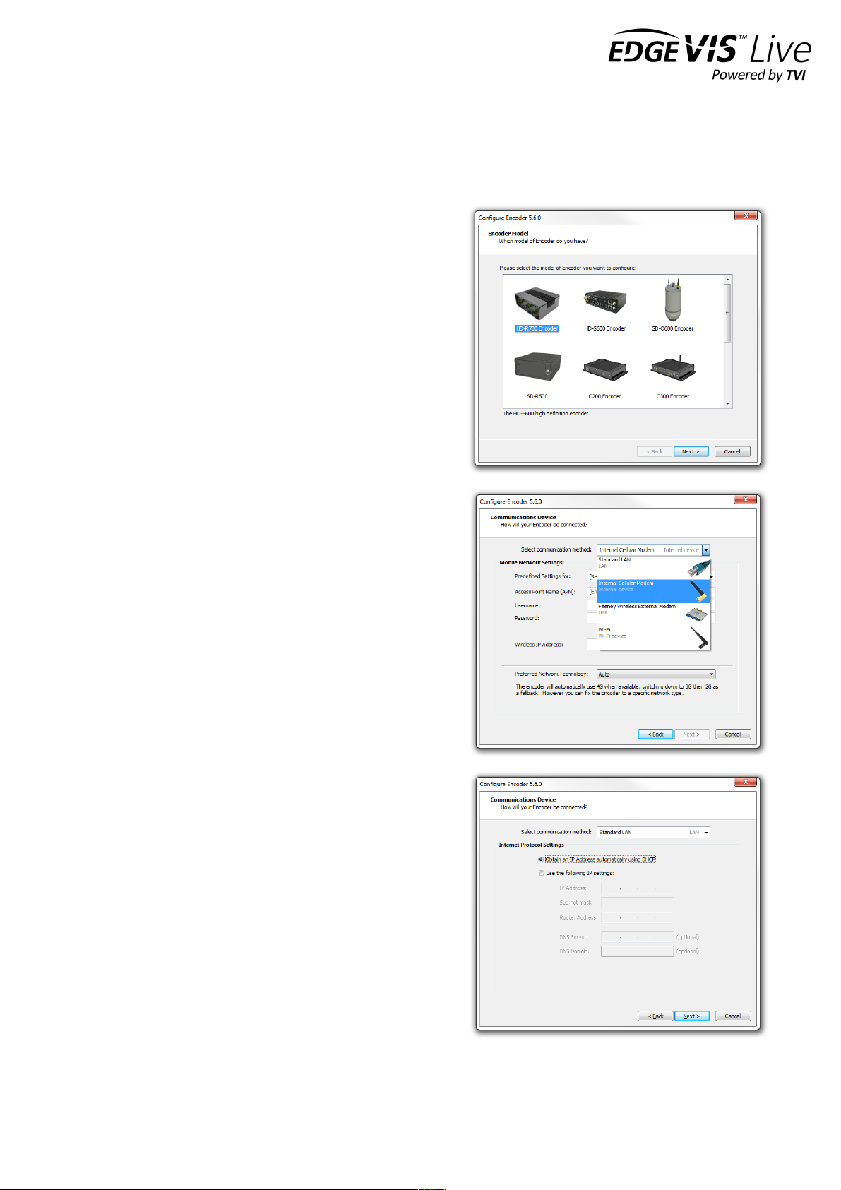
When preparing an HD-R700 for use, the most appropriate and practical method should be adopted. Only one of the
methods need be completed for each encoder and both methods cover the same operational parameters and details.
• Option 1: Using the USB-based Configuration Application
If organisational policies allow the use of computer USB ports, using the configuration application on the USB
flash drive (supplied) is a quick and easy way to define and install the configuration settings for an HD-R700.
The application includes a Windows-based wizard that guides the user through a variety of settings, before
saving these back to the USB flash drive and delivering the configuration into HD-R700 by plugging in the
drive.
• Option 2: Using the web-based setup Interface
If organisational policies preclude the use of USB ports on computers (for example for security reasons) or if
the web-based method is preferable to USB configuration, the Setup Interface offers an alternative approach
to preparing an encoder. For this method, a laptop/PC is connected locally to the HD-R700 using an Ethernet
cable and the setup application is launched via a web browser. This requires the user to specify an IP address
for the computer that is in the same IP range as the HD-R700. For further details on this, refer to Appendix B.
Note that the HD-R700 must be configured using ONE of the two configuration methods described before it can be
deployed.
The following section outlines the steps involved in both options.
EDGEVIS HD-R700 HARDWARE INSTALLATION GUIDE
ISSUED: 9 FEBRUARY 2018 PAGE 11
Option 1: Using the USB Configuration Application
The HD-R700 can be configured using the USB configuration application provided on the USB flash drive that is
distributed with the HD-R700 encoder. This method creates a configuration settings file on the USB flash drive profile
on a computer that is then transferred back onto the USB flash drive, before insertion into the HD-R700 to apply the
configuration settings.
Accessing the Configuration Application
Insert the USB flash drive into a PC running Microsoft Windows
XP (or later) operating system.
Navigate to the flash drive using Windows Explorer, or select the
view files option if a Windows prompt appears with a list of
Auto-play actions.
Locate the configuration application file (it will appear on the
flash drive as ‘ConfigureEncoder6.x.x.exe’) and double-click to
launch the configuration app. Once it has launched, select HD-
R700 Encoder from the list of encoders.
Setting up the communication method
Select the connection method that is appropriate to your
operational requirement. The lower section of the wizard will
change to reflect the configuration options for the selected
connection method:
• Standard LAN connection - the encoder will connect
to any network/device with a standard LAN interface
• Cellular Modem - the encoder has an inbuilt cellular
modem supporting HSDPA, 3G/4G, EDGE and GPRS
• Wireless LAN (Wi-Fi) - the encoder will connect to a
Wi-Fi network using the inbuilt Wi-Fi module
Connection settings for LAN based connections
If the selected connection method is LAN, it is possible to edit
the network configuration of the LAN connection. The
Communications Device dialog options allow for the
entering/editing of the IP details of the LAN connection. In
most cases, the encoder will use DHCP to obtain its network
settings automatically from the network gateway.
If the network does not provide a DHCP address to the
encoder select Use the following IP settings and enter
settings that are valid for the network that the encoder is
joining. A DNS Server and Domain is only required if the
supplied EdgeVis Server address is a resolvable host name (e.g.
video.server.com) and not an IP Address (e.g. 192.168.50.10).

EDGEVIS HD-R700 HARDWARE INSTALLATION GUIDE
ISSUED: 9 FEBRUARY 2018 PAGE 12
Connection settings for cellular connections
If the selected connection method is Internal Cellular
Modem, the Communications Device dialog allows for
selection of a network provider. The wizard has predefined
settings for most major UK and North American mobile
operators – to use one of these simply select the operator
from the Predefined Settings for list box. The appropriate
details for the mobile operator will be entered automatically.
Otherwise enter the correct APN, username and password for
the mobile network.
The predefined settings are correct as of April 2016 but these
are subject to change by the mobile operators at any time.
Confirm with the selected mobile operator that the
predefined settings are still appropriate.
Connection settings for Wi-Fi connections
If the selected connection method is Wi-Fi the
Communications Device dialog changes to enable the details
of the appropriate wireless networks to be entered.
The encoder will maintain a list of Wi-Fi networks that it will
attempt to connect to. Enter the SSID and network key for
each network that will be used. Then for each network either
configure DHCP or specify IP settings to use.
The encoder will automatically scan for available Wi-Fi
networks and select a working connection from the list.
Select the backup communication method
The encoder can be configured to use a second backup communication connection in case of a failure to the primary
communications method. The drop down menu at the top will list the remaining connections that could be used to
provide a backup capability. For most installations it is likely that the default setting of Not Enabled is correct.
For further information and help configuring the failover capabilities refer to the Knowledge Base Article - Using the
Communication Failover Feature on the Support Site
EDGEVIS HD-R700 HARDWARE INSTALLATION GUIDE
ISSUED: 9 FEBRUARY 2018 PAGE 13
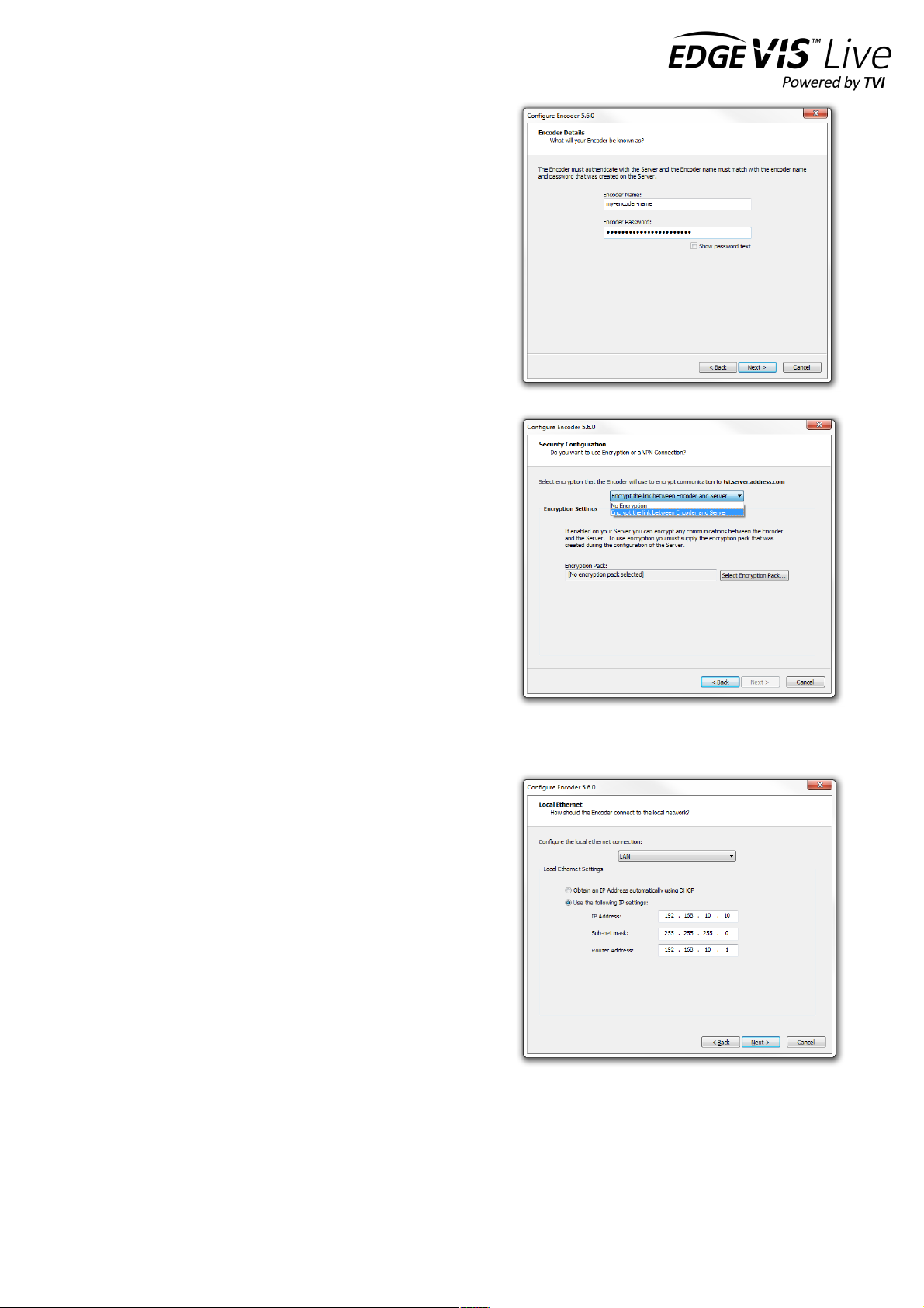
Entering the encoder and server details
Each encoder requires an encoder account be created on an
EdgeVis Server. Enter the details of the account that was
created for this encoder.
Enter the IP address or domain name that the encoder will use
to communicate with the EdgeVis Server. This can either be an
IP address (e.g. 12.87.54.255) or a domain name (e.g. video-
server.company.com).
A primary and secondary EdgeVis Server can be configured. If
the primary server fails, the encoder will automatically connect
to the secondary server.
Applying encryption and security settings
The pull down menu at the top of the Encryption page allows
for two different options:
No Encryption - traffic between the encoder and EdgeVis
Server will be unencrypted.
Encrypt the link between encoder and Server - encrypt the
traffic between encoder and EdgeVis Server using the built-in
AES encryption. This requires the Encryption Pack that can be
downloaded from the Server Status page within EdgeVis
Server.
For further information and help configuring the encryption
capabilities refer to the Knowledge Base Article Using
Encryption with EdgeVis products on the Support Site
Setting up the local Ethernet port
This dialog allows changes to the Local Ethernet port of the HD-
R700. The local Ethernet port is only used to access the local
ONVIF output stream and the browser-based Setup Interface.
Either click the Obtain an IP Address automatically using
DHCP radio button to use DHCP to automatically obtain an IP
address, or click the Use the following IP settings radio button
to allow the manual entry of IP address, subnet mask and router
address.

EDGEVIS HD-R700 HARDWARE INSTALLATION GUIDE
ISSUED: 9 FEBRUARY 2018 PAGE 14
Configure Local Wi-Fi Download mode
The next step, if required, is to enable the Local Wi-Fi Download
feature. There are two modes of operation; ‘Always On’ mode and
‘Switched’ mode (where users can use EdgeVis Client to remotely
enable/disable the access point).
After selecting the mode, enter a Network Name and Network
Key for the Access Point (that the HD-R700 will broadcast), an IP
Address that will be used to connect to the download web page,
and a Download password to log in to the download web page.
For information on using the Local Wi-Fi Download feature refer
to the Knowledge Base Article - HD-S600 HD-R700 - Local Wi-Fi
Download Interface.
Specify NAS recording location
It is possible to utilise a NAS device or Windows Share location to
store recordings. This will add the NAS into the storage pool and
so it is recommended to remove any external USB drives from the
encoder.
If NAS recording is required enter the IP Address, share name,
username and password of the share.
For information on using a NAS for recordings refer to the
Knowledge Base Article – Configuring NAS support for HD-S600
HDR700.
Specify time zone and archive encryption
It is possible to encrypt the archive footage for secure viewing of
extracted footage using Export Player. This requires a user to
enter the archive password to open any recording files. To enable
archive encryption, click the Enable Archive Encryption check
box then enter a password.
To ensure that the video playback time displayed in the viewing
application will be correct, select the Encoder Time zone for the
area that the encoder will be operating in. Note that Military time
zones are available by checking the Include Military Time Zones
box.

EDGEVIS HD-R700 HARDWARE INSTALLATION GUIDE
ISSUED: 9 FEBRUARY 2018 PAGE 15
Finalising and applying configuration to encoder
When all of the settings have been entered, click the Finish button to close the wizard. The configuration on the USB
flash drive can now be applied to the encoder. Safely eject the USB flash drive from the computer and then plug it into
the socket marked SYSTEM USB on the encoder, powering the encoder if necessary.
If the Status Dongle is available, observe the LEDs - the encoder will shortly begin applying the configuration
(displaying orange pulsing lights), and will display all green lights once complete. If an LED Status Dongle is not
available, allow enough time (approximately 4 minutes) for the settings to be applied before removing the keypen or
powering down the unit.
Remove the USB flash drive when the application of settings complete, and the encoder will reboot and attempt to
establish its communications links and connect to EdgeVis Server.
To verify the encoder is set up correctly, attempt to view the video stream or check the encoder’s connected status via
the EdgeVis Web Manager. If using the LED Status dongle refer to Encoder LED Status in Section 1 for an
explanation of the encoder's boot sequence and corresponding LED status.
EDGEVIS HD-R700 HARDWARE INSTALLATION GUIDE
ISSUED: 9 FEBRUARY 2018 PAGE 16
Option 2 - Using the web-based setup Interface
If the USB-based configuration approach is not practical, the HD-R700 can also be configured using the web-based
setup interface. This method requires a laptop/PC and Ethernet cable to connect to the unit.
Establish a connection between the computer and the HD-R700
In order to access and run the Setup Interface the encoder must first be connected to the laptop/PC that is to be used
to perform the setup. Connect an Ethernet cable from the computer to the Local Ethernet port on the unit. The
computer must be in the same IP range as that of the local Ethernet port of the unit. This is set to 192.168.10.10 as the
default. This IP address can be changed during the setup process. Further details on specifying IP addresses (on the
setup computer and HD-R700) can be found in Appendix B.
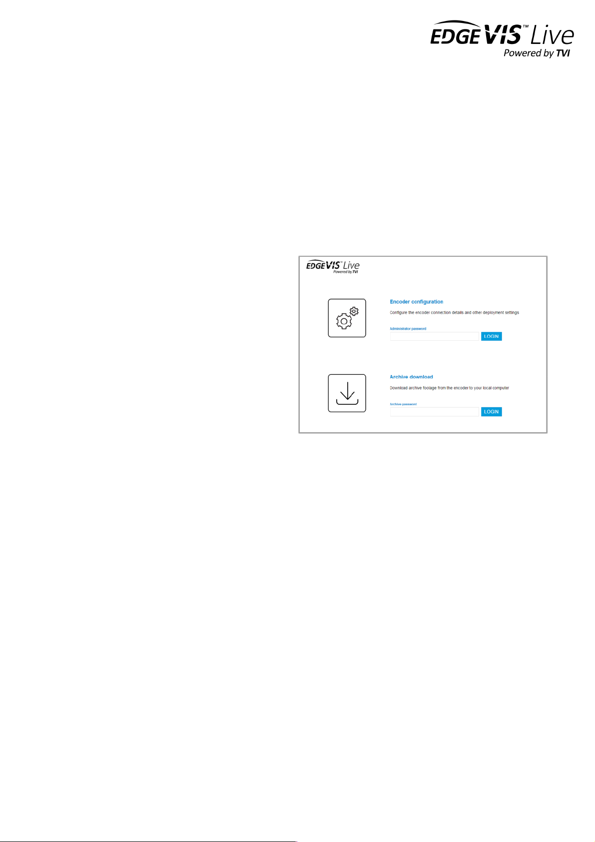
Log in to the setup interface
To access the Setup Interface, enter the following
address in the web browser: http://192.168.10.10. Once
connected to the HD-R700 there will be two options,
Configuration and Archive Download. In the
Configuration panel enter the encoder's configuration
password - the default password is password.
If this is the first time of use, the default password should
be changed. To change the password, click the CHANGE
PASSWORD button. Enter the current and new
passwords into the dialog then click Apply. The system
will re-display the Login page to allow login using the
new password. Log in with the new password.
The HD-R700 configuration home page
Once logged in, the main configuration home page is displayed. This will present a summary of the encoder's
communication and server settings, as well as displaying the encoder's current status.
The page is split into four areas:
• Communication Settings
• Server Settings
• Local Settings
• DVR Settings
To continue enter each section using the EDIT button to enter the appropriate settings for each area.

EDGEVIS HD-R700 HARDWARE INSTALLATION GUIDE
ISSUED: 9 FEBRUARY 2018 PAGE 17
Communication Settings - specify the encoder connection methods
The first setting required is the connection method (or
bearer) to be used by the encoder to communicate with
EdgeVis Server. Two connections can be configured; a
primary connection that is the default connection
method and a secondary connection for failover if the
primary method fails. Note that selection and
configuration of a secondary method is not mandatory.
Select the appropriate communications method from
the Primary Communications drop-down and enter the
details.
• Standard LAN connection: the unit will connect to any network/device with a standard LAN interface
• Cellular Modem: the unit has an inbuilt 3G/4G cellular modem
• Wireless LAN (Wi-Fi): the unit will connect to a Wi-Fi network using the inbuilt Wi-Fi module
Note - For further guidance on the settings required for each connection method, refer to the Setting up the
communication method section in the instructions for Using the USB Configuration Application.
Once the information for the primary communications method is complete, enter details about the desired secondary
communications method (if this is required). Note that the primary option will not be available for selection as the
secondary method.
Server settings - specify the server and encoder account details
In order to communicate with EdgeVis Server, the
HD-R700 encoder unit must be configured with the
correct encoder and EdgeVis Server details.
Enter the encoder name and password of the
encoder account that was created for this HD-R700
on EdgeVis Server.
Enter the IP address (e.g. 12.87.54.255) or domain
name (e.g. video-server.company.com) that the unit
will use to communicate with the EdgeVis Server.
To enable encryption between the HD-R700 and the
server using built-in AES Encryption, click the Enable Encryption check box and upload the Encryption pack.
If necessary, a System Administrator can download the encryption pack from the Server Status page once logged into
EdgeVis Server.
EDGEVIS HD-R700 HARDWARE INSTALLATION GUIDE
ISSUED: 9 FEBRUARY 2018 PAGE 18
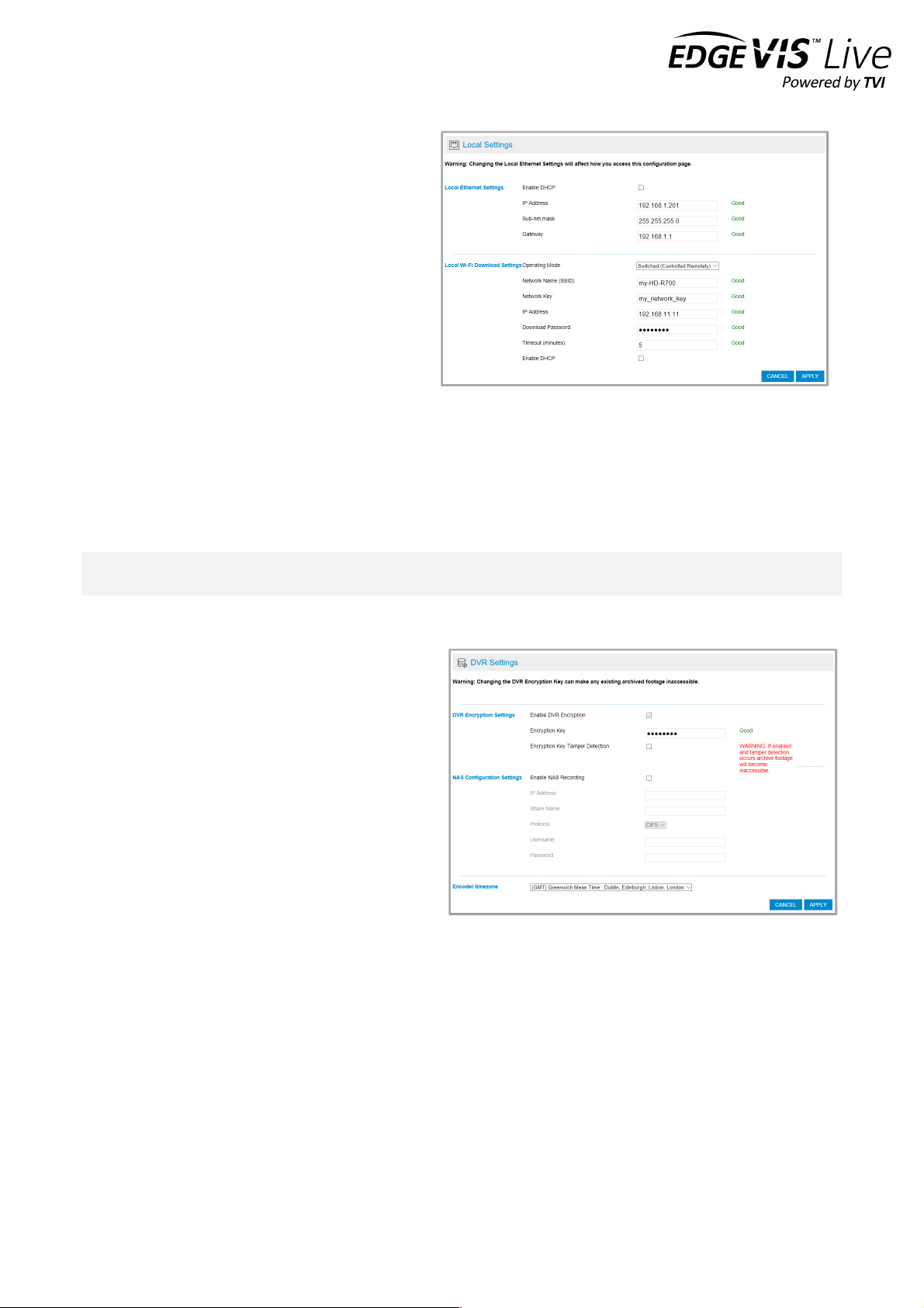
Local Settings - specify how the user can interact with the encoder locally
This page allows the user to change the IP address of
the local Ethernet port. Be aware that changing this
setting will require logging into the encoder again,
using the new IP Address. This may also require the
user to reconfigure their PC to match the new
settings.
The next section on the page allows the user to
configure the Local Wi-Fi Download feature. There
are two modes of operation: Always On mode and
Switched mode. The latter is provided to allow a HD-
R700 unit to switch between Wi-Fi streaming and
local Wi-Fi download, when using Wi-Fi as the
primary or secondary communications bearer.
Refer to the Knowledge Base Article - HD-S600 HD-R700 - Local Wi-Fi Download Interface for further information on
when to use each mode.
Once a mode is selected, enter a Network Name and Network Key for the Access Point (that the HD-R700 will
broadcast), an IP Address that will be used to connect to the download web page (via a laptop), and a Download
password that is required to log in to the download web page.
Note - Ensure that the Local Ethernet and Local Wi-Fi IP addresses are on different subnets. For example, this could
be 192.168.10.10 for Ethernet and 192.168.20.10 for Wi-Fi. For further information, consult your IT admin.
DVR Settings - specify recording options
The final configuration page is DVR Settings.
It is possible to encrypt the archive video, requiring the
user to enter an archive password when accessing the
recording files using Export Player. To enable
encryption, check the Enable DVR Encryption check
box and enter an encryption key in the DVR
Encryption Key text box.
It is also possible to utilise an external NAS device as a
recording location. This allows users to take
advantage of any NAS or PC that can provide a
Windows file share (or compatible CIFS share). For
further details, refer to the Knowledge Base Article –
Configuring NAS support for HD-S600 HD-R700.
If NAS recording is required enter the IP Address, Share name, username and password of the share. This will add the
NAS into the storage pool and so it is recommended to remove any external USB drives from the unit.
Finally, to ensure that the video playback time displayed in the viewing application is accurate, select the geographical
time zone of where the encoder is located.

EDGEVIS HD-R700 HARDWARE INSTALLATION GUIDE
ISSUED: 9 FEBRUARY 2018 PAGE 19
Section 3 – Next Steps…
After completing the steps contained within the previous sections you
should have an HD-R700 encoder connected to an EdgeVis Server. This
section outlines the steps you should take next.
Configuring the streaming parameters
Once the encoder is configured and connected to EdgeVis Server, it is possible to perform a more in-depth
configuration of the encoder using EdgeVis Server’s web configuration interface. Refer to the Knowledge Base Article
– Configuring an encoder using EdgeVis Server for further details.
Installing a viewing client
Once the encoder is configured and connected to EdgeVis Server the next step is to install EdgeVis Client to allow
remote access to, and viewing of, the video from the encoder. EdgeVis Client is available on Windows, iOS or Android,
and can be downloaded directly from the Digital Barriers Support Site, along with the EdgeVis Client Guide.

EDGEVIS HD-R700 HARDWARE INSTALLATION GUIDE
ISSUED: 9 FEBRUARY 2018 PAGE 20
Appendix A - Frequently asked questions
How many channels does the HD-R700 support?
The HD-R700 can record up to two camera inputs and transmit one camera from any of the three inputs.
What level of recording and streaming performance is achievable?
Based on the processing power of the HD-R700, the encoder can typically achieve 15 fps of 1080p quality recording
whilst simultaneously streaming one 1080p quality video at close to full frame rate of 7.5 fps.
What recording functions does the HD-R700 support?
The HD-R700 can be set up to record continuously, which can be enabled/disabled remotely.
What indicative recording times and streaming rates are achievable?
The HD-R700 records the incoming video stream from each camera without modification. The recording options set
(e.g. frame-rate, bandwidth, bit-rate) will directly affect the recording time. Below are the approximate recording
times for various storage options when recording the HD-SDI camera:
Frame rate
480GB drive
1 TB drive
Very High (4 mbits/sec)
12 days
24 days
High (2 mbits/sec
24 days
48 days
Normal (1 mbits/sec)
48 days
96 days
Medium (0.5 mbits/sec)
96 days
192 days
What bearers can the HD-R700 use to transmit video to EdgeVis Server?
The HD-R700 can use its inbuilt cellular modem for efficient streaming over commercially available cellular networks. It
can also transmit using its inbuilt LAN port or Wi-Fi module. EdgeVis optimises its transmission to the characteristics
of the bearer that it is being used to maximise performance.
How does EdgeVis Server licensing work in relation to the HD-R700?
Within the EdgeVis Server licensing model the HD-R700 is classed as an EdgeVis Specialist device. An HD-R700
encoder requires one EdgeVis Specialist licence be available on the EdgeVis Server.
Table of contents
Other Digital Barriers Media Converter manuals


