DIGITIZE DET-6B User manual

DET-6B/12B
INSTALLATION
AND
OPERATION MANUAL
Digitize, Inc.
158 Edison Road
Lake Hopatcong, NJ 07849
el: (973) 663-1011 Part Number 700158-0000
Fax: (973) 663-4333 Issue Revision: F
E-mail: <info>@digitize-inc.com Issue Date: 02/16
Website: http://www.digitize-inc.com

he DIGI IZE logo is registered trademark of Digitize, Inc.

PROPRIETARY NOTICE
AND DISCLAIMER
DIGITIZE, INC.
158 EDISON ROAD
LAKE HOPATCONG, NJ 7849-2217
PH: (973) 663-1 11
FAX: (973) 663-4333
E-Mail: info@digitize-inc.com
Website: http://www.digitize-inc.com
This manual has been prepared by DIGITIZE, INC. for use by its licensees, distributors
and customers. The information contained herein is the property of DIGITIZE, INC. and
may not be copied, disclosed or reproduced, in whole or in part, without the prior written
approval of DIGITIZE, INC. ny unauthorized disclosure to, or use of the enclosed
information by, unauthorized third persons shall void any and all representations,
warranties and obligations on the part of DIGITIZE, INC.
DIGITIZE, INC. reserves the right to make changes to the specifications and material
contained herein without prior notice. The information and/or examples (including, but
not limited to circuitry, wiring diagrams, programming, the operation or use shown)
described in this manual are intended solely to illustrate the operating principles of the
particular product. They are not a warranty, representation or guarantee that a particular
example or use shown will perform in a particular situation. They are given for illustration
purposes only. DIGITIZE, INC. shall not be responsible, nor does it represent, that any
example of illustration will perform in a particular environment or practice unless it
specifically makes a representation to that effect.
The material set forth herein is for informational purposes only, and DIGITIZE, INC.
assumes no patent liability with respect to any information or illustrations contained
herein.


i
TABLE OF CONTENTS
SECTION 1 GENERAL INFORMATION 1-1
1.1 SYS EM DESCRIP ION 1-1
1.2 DESCRIP ION 1-1
1.3 AC IVA ION OF INPU S 1-2
1.4 REPOR ING PRIORI Y 1-2
1.5 NUMBER OF ROUNDS 1-3
1.6 RANSMISSION SPEED 1-3
1.7 EPROM 27C512 1-3
1.8 LED INDICA ORS 1-3
1.9 SPECIFICA IONS 1-3
1.9.1 CURREN CONSUMP ION 1-3
1.9.2 DEMENSIONS 1-3
1.10 APPLICABLE PUBLICA IONS 1-4
SECTION 2 PROGRAMMING THE DET-6B/12B EPROM 2-1
2.1 DIGI IZE, INC. DE -6B/12B PROGRAM DA A LOCA IONS 2-1
2.2 PROCEDURE FOR USING HE DE -PROG PROGRAMMER 2-5
2.2.1 IMING AND OP IONS 2-7
2.2.2 SE ELEGRAPH CODES 2-9
SECTION 3 INSTALLATION 3-1
3.1 HANDLING 3-1
3.2 SI E LOCA ION 3-1
3.3 INS ALL ION DE AILS 3-1
SECTION 4 THEORY OF OPERATION 4-1
4.1 GENERAL 4-1
4.2 WA CH DOG IMER 4-1
SECTION 5 MAINTENANCE 5-1
5.1 PRECAU IONS 5-1
5.2 ROUBLESHOO ING 5-1
5.3 BA ERY MAIN ENCE 5-2
SECTION 6 DET-6B DUAL LINE 6-1


DE -6B/12B INS ALLA ION AND OPERA ION MANUAL
DIGI IZE, INC. 700158-0000 REV.F 02/16 1-1
SECTION 1
GENERAL INFORMATION
1.1 SYSTEM OVERVIEW
he DIGI IZE Electronic ransmitter, Six Zone (DE -6B) is a solid-state
microprocessor coder for use over telegraph hard wire. he DE -6B is designed to
operate with a loop current from 50 mA to 750 mA. A dual 6-zone version (DE -12B) is
available in a larger enclosure.
1.2 DESCRIPTION
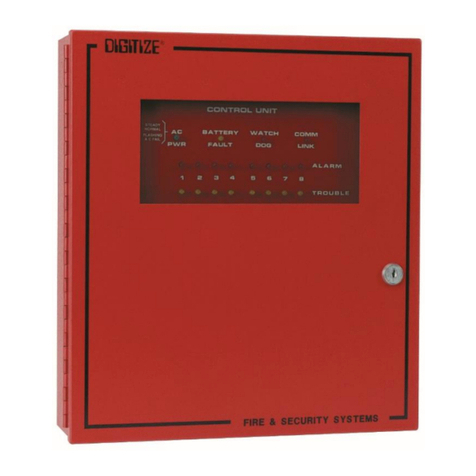
he DIGI IZE DE -6B is a elegraph ransmitter for Fire and Security Alarms. he
unit has six End of Line (EOL) resistor zones and includes a CAM lock, AC transformer,
standby battery and built-in charger. he unit is housed in a steel enclosure and is
suitable for mounting in convenient, out of the way locations on an interior wall. he
DE -6B can be used on the same loop with mechanical Fire Alarm Boxes.
elegraph codes unique to each of the six zones for rouble, Alarm and Secure as well as
Low Battery are transmitted over a 100 millampere circuit using PNIS (Positive Non-
Interfering Successive). he DE -6B has line current detection to avoid clashes between
more than one transmitting device. Automatic ground return, a Watch Dog imer, and a
jumper selected internal trouble buzzer assure continued main system operation and
operator notification in the event of a box failure. A built-in trouble relay output (Form
C), the ground and code relay (grounding, opening, or no effect on the 100 mA line) are
activated by the Watch Dog imer ensuring reliable failure detection.
ransmission speed is adjustable to match existing decoding units, as are the number of
digits for the box number and the last digit for alarm, trouble, and restore. Number of
rounds for each condition is also programmable.
Automatic switchover to battery power is performed upon AC power loss with a low
battery code transmitted if power is not returned in approximately 60 hours. After
transmitting a low battery code, the unit bypasses all input circuits to avoid spurious
transmission of false alarms.

DE -6B/12B INS ALLA ION AND OPERA ION MANUAL
DIGI IZE, INC. 700158-0000 REV.F 02/16
1-2
1.3 ACTIVATION OF INPUTS
here are six inputs zones for the ransmission of Alarms, roubles, Low Battery (if
desired) and for Restore of Condition (if desired). he DE -6B/12B is fully
programmable, allowing for a short to generate a selected code and the number of rounds.
he trouble (an open line on the input) is also programmable, allowing a selected code
and number of rounds to be generated. Each box number transmitted contains the “base”
number (one to five digits) plus a single suffix digits. his allows transmission of Alarm
Codes for either a short or open line condition at the input zones. he DE -12B uses 2
of the 6 zone boards.
When a zone input goes into Alarm, the DE -6B/12B will send the code number for the
unit followed by the code that was selected for the zone that went into Alarm.
For example, Zone 2 shorted with the following parameters:
4 rounds box code 1234, zone code 2
12342
12342
12342
12342
As another example: Zone 2 opened with following parameters:
4 rounds box code 1234, zone code 8
12348
12348
12348
12348
he zone code is the last digit following the one to five digit identification code.
INCOMING BOX 12341 indicates Box 1234, Zone 1
INCOMING BOX 652265 indicates Box 65226, Zone 5
INCOMING BOX 434 indicates Box 43, Zone 4
1.4 REPORTING PRIORITY
Zone 1 is the highest priority. Priority descends in numerical order down to Zone 6,
which would be reported last. In the case of several different conditions happening at
once, alarms are reported first, followed by restores on alarms. rouble conditions (open
circuits) are the next lower level of priority, Zone 1 to Zone 6), followed by restores on
trouble.

DE -6B/12B INS ALLA ION AND OPERA ION MANUAL
DIGI IZE, INC. 700158-0000 REV.F 02/16 1-3
1.5 NUMBER OF ROUNDS
Rounds are individually programmable of each zone of Alarm, rouble and Restore. For
example, four rounds for Alarm and one round for Restore are standard values on the
Master EPROM.
1.6 TRANSMISSION SPEED
he speed of transmission is adjustable over a range from 1/8 to four seconds in steps of
approximately 1/24 second, and is changed by programming the equivalent number on
the EPROM. he standard value on the Master EPROM is 1/4 second, with a value of
06, which represents approximately 6/24. See page 2-3, location 7B3 for calculation.
1.7 EPROM 27C512
A blank 27C512 EPROM is supplied with each DE -6B. he 27C512 EPROM is
programmed using Digitize DE -PROG programmer. he DE -12B is supplied with 2
EPROMS.
1.8 INDICATORS LEDs
Watch Dog (Red): Pulses once every four seconds in standby mode and with the code
while transmitting.
rouble (Yellow): Non-latching indication of any existing trouble condition.
Main Power (Green): On when 14-16 VAC or 24 VDC of the correct polarity is
present on terminals 1 and 2.
On Line (Red): On when the unit activates to transmit with a good line. his LED
will be off when the unit is transmitting to ground with an open
line.
1.9 SPECIFICATIONS
1.9.1 Current Consumption
Less than 100mA standby, 170 mA max operating.
1.9.2 Dimensions
DE -6B 12.0 in x 11.5 in x 3.5 in
DE -12B 15.0 in x 13.5 in x 4.0 in

DE -6B/12B INS ALLA ION AND OPERA ION MANUAL
DIGI IZE, INC. 700158-0000 REV.F 02/16
1-4
1.1 APPLICABLE PUBLICATIONS
-
National Fire Protection Association (NFPA) standards 72 proprietary, 1221.

DE -6B/12B INS ALLA ION AND OPERA ION MANUAL
DIGI IZE, INC. 700158-0000 REV.F 02/16 2-1
SECTION 2
PROGRAMMING THE DET-6B/12 EPROM
he DE -6B is supplied with one 27C512 EPROM for the storing of the data, which is to be
transmitted when any input is activated. A DE -12B is supplied with two EPROMS.
In order to program the DE -6B/12B EPROM for operation, the information can either be sent
to DIGI IZE, INC with the purchase order for the DE -6B/12B or programmed using the
DE -PROG EPROM programmer for the PC.
2.1 DIGITIZE, INC. DET-6B/12B PROGRAM DATA LOCATIONS
he following memory locations, presented in numerical order, in the 27C512 EPROM
control the functions as noted. he S D column indicates the default value, if not
otherwise indicated; USER can be filled in by the user to indicate desired custom values.
Addresses below are from the DE -6 Programmer. If using a standard EPROM
programmer, the locations are from FF80-FFFF.
ADDRESS DESCRIPTION STD
USER
780-785 Not used. Standard = 00
786
Waiting time for a good line.
00 to 9.9 seconds in tenths.
(02 = 0.2 seconds, standard) 02
787
Waiting time for an open line.
00 to 64 seconds.
(24 = 24 seconds, standard) 24
788
Waiting time for busy line. 00 to 9.9 minutes in tenths.
(20 = 2.0 minutes, standard)
00 = the unit starts to transmit only when the line is free. 20

DE -6B/12B INS ALLA ION AND OPERA ION MANUAL
DIGI IZE, INC. 700158-0000 REV.F 02/16
2-2
ALARM CODES TROUBLE CODES
ADDRESS STD USER ADDRESS STD USER
789 Zone 1 01 78F Zone 1 07
78A Zone 2 02 790 Zone 2 07
78B Zone 3 03 791 Zone 3 07
78C Zone 4 04 792 Zone 4 07
78D Zone 5 05 793 Zone 5 07
78E Zone 6 06 794 Zone 6 07
795 Low Battery 09
Number of rounds to transmit for activation of:
ALARM CODES TROUBLE CODES
ADDRESS STD USER ADDRESS STD USER
796 Zone 1 04 79D Zone 1 03
797 Zone 2 04 79E Zone 2 03
798 Zone 3 04 79F Zone 3 03
799 Zone 4 04 7A0 Zone 4 03
79A Zone 5 04 7A1 Zone 5 03
79B Zone 6 04 7A2 Zone 6 03
79C Not used 00 7A3 Low Battery
03
Number of rounds to transmit for restore of:
ALARM CODES TROUBLE CODES
ADDRESS STD USER ADDRESS STD USER
7A4 Zone 1 01 7AA Zone 1 02
7A5 Zone 2 01 7AB Zone 2 02
7A6 Zone 3 01 7AC Zone 3 02
7A7 Zone 4 01 7AD Zone 4 02
7A8 Zone 5 01 7AE Zone 5 02
7A9 Zone 6 01 7AF Zone 6 02
7B0 Low Battery
02

DE -6B/12B INS ALLA ION AND OPERA ION MANUAL
DIGI IZE, INC. 700158-0000 REV.F 02/16 2-3
ADDRESS DESCRIPTION STD USER
7B1
Choice of Bulldog option_________
01 = YES (transmits over any unit_______ on the line)
(No PNIS)
00 = NO (has PNIS) 00
7B2
Buzzer activation time. 00 to 9.9 in tenths.
(40 = 4.0 minutes, standard) 40
7B3
ransmission (box) speed, 1/8 to 4 seconds
(06 = 1/4 seconds, standard)
Value equals Speed X 23 (i.e., 1/4 X 23 = 5.75 or 06.) 06
7B4
K2 Open inter digit delay
(04 is standard for municipal box) 04
DO NO
CHG
7B5
K2 close inter digit delay.
(01 is standard for municipal box) 01
DO NO
CHG
7B6
K2 open inter round delay
(12 is standard for municipal) 12
DO NO
CHG
7B7
K2 close inter round delay.
(01 is standard for municipal box) 01
DO NO
CHG
7B8
OPEN or CLOSE Index ransmission
00 = OPEN Index (municipal box) is standard
01 = CLOSE Index (Boston box) 00
7B9
Open inter digit delay between first and second digit.
(04 is standard for municipal box)
(06 is standard for Boston Box) 04
Code for restore of:
ALARM CODES TROUBLE CODES
ADDRESS STD USER ADDRESS STD USER
7BA Zone 1 01 7C0 Zone 1 07
7BB Zone 2 02 7C1 Zone 2 07
7BC Zone 3 03 7C2 Zone 3 07
7BD Zone 4 04 7C3 Zone 4 07
7BE Zone 5 05 7C4 Zone 5 07
7BF Zone 6 06 7C5 Zone 6 07
7C6 Low Battery
09
ADDRESS DESCRIPTION STD USER
7C7
Additional delay before going into ground mode, in 1/10
of a second. (20 = 2 seconds) 20

DE -6B/12B INS ALLA ION AND OPERA ION MANUAL
DIGI IZE, INC. 700158-0000 REV.F 02/16
2-4
he following code number locations contain five digits followed by 00. If a box contains less
than five digits, fill the balance of the box number with 00’s. he sixth digit is always 00. For
example, Box 123 is represented by 1, 2, 3, 00, 00, 00.
ZONE 1 ZONE 2
ADDRESS STD USER ADDRESS STD USER
7C8 01 7CE 02
7C9 02 7CF 02
7CA 03 7D0 03
7CB 00 7D1 00
7CC 00 7D2 00
7CD 00
MUS BE 00
7D3 00
MUS BE 00
ZONE 3 ZONE 4
ADDRESS STD USER ADDRESS STD USER
7D4 03 7DA 04
7D5 02 7DB 02
7D6 03 7DC 03
7D7 00 7DD 00
7D8 00 7DE 00
7D9 00
MUS BE 00
7DF 00
MUS BE 00
ZONE 5 ZONE 6
ADDRESS STD USER ADDRESS STD USER
7E0 05 7E6 06
7E1 02 7E7 02
7E2 03 7E8 03
7E3 00 7E9 00
7E4 00 7EA 00
7E5 00
MUS BE 00
7EB 00
MUS BE 00
LOW BATTERY
ADDRESS STD USER
7EC 07
7ED 02
7EE 03
7EF 00
7F0 00
7F1 00 MUS BE 00
ADDRESS DESCRIPTION STD USER
7F2 Special selection on Zone 6 for DE -6D 00 Must be 00

DE -6B/12B INS ALLA ION AND OPERA ION MANUAL
DIGI IZE, INC. 700158-0000 REV.F 02/16 2-5
In Normal mode, the rouble output is activated (set to rouble) when a rouble (ZONE OPEN
or LOW BA ERY AC IVA ED) is detected. If an alarm occurs during the transmission of a
restore of an alarm, or an activation or restore of a trouble, the transmission is interrupted at the
end of the round and the alarm is transmitted. When transmission of the alarm is complete, the
restore of an alarm, or activation or restore of the interrupted trouble is transmitted again (from
the beginning). he rouble Output stays in a trouble condition while a trouble is present.
NOTE: ransmission of LOW BA ERY (AC IVA ION or RES ORE) is not interrupted if
an alarm is activated during transmission.
ADDRESS
DESCRIP ION
7F3-7F5 Date Code Location. Do not change these codes.
hey serve to identify the program.
7F6-7FF CAUTION! Do not modify these addresses. hey
contain data, which is vital for proper operation of the
transmitter.
2.2 PROCEDURE FOR USING THE DET-6 PROGRAMMER
he following instructions and locations are for the proper programming of the DE -
6B/12B elegraph ransmitter. he entering of the this information will generate a
MAS ER EPROM chip which then can be used over and over for the particular
installation.
his information can be loaded by someone other than DIGI IZE, INC by using the
DE -6 EPROM Programmer for the PC.
he programmer software is easily installed on your PC with the instructions supplied.
he Online Help (accessed by the F1 key) guides you through the procedure of editing
data and programming the 27C512 EPROM. he following information is a guide to the
data screens that display when you are using the DE -6 programmer. Each screen has
default values already entered, but you may change them according to the desired
functionality.
NOTE
: If DIGI IZE, INC is doing the programming, the information will be
loaded as stated on the programming sheets that follow. DIGI IZE is not
responsible for errors or omissions in the programming if the sheets are not filled
out completely or correctly. DIGI IZE’s only responsibility will be to reprogram
another chip if there is an error on our part.

DE -6B/12B INS ALLA ION AND OPERA ION MANUAL
DIGI IZE, INC. 700158-0000 REV.F 02/16
2-6
When you first load the program, the following screen will appear:
Press any key to continue. he Main System HELP screen will appear. Press any key to
continue. he main menu will appear.
Select the menu of your choice, either by moving the Light Bar to the desired line, and
pressing, “EN ER”; or by pressing the letter on the keyboard that corresponds to the
capitalized letter in the desired line.
Configure Programmer - Provides additional functions relating to testing and
programming the blank EPROM.
Timing and Options – Allows the parameters associated with timing to be changed.
Set Telegraph Codes – Allows the codes and number of rounds associated with alarms,
troubles, restorals and low battery to be changed.
Program the EPROM – Permits user to check, verify, read and program an EPROM.
DO NO select the Edit then program option. his is an advanced feature of the program
that should only be used in extreme conditions.
DE - 6 PROM
A DIGI IZE DE -6B U ILI Y
DIGI IZE, INC. LAKE HOPA CONG, NJ
PHONE: (973) 663-1011
© 1990-1994 All Rights Reserved
Version: XXX XX, XXXX
Written by: om Walsh, WN3L
Mouse was found and connected
(Press any key to continue)
DE -6B Programmer
conFigure programmer
imings and options
set telegraph Codes
Program the EPROM
Record site data
Load old site data
Quit back to MSDOS

DE -6B/12B INS ALLA ION AND OPERA ION MANUAL
DIGI IZE, INC. 700158-0000 REV.F 02/16 2-7
Record Site Data – Permits the user to save the current settings under a name that
associates the settings with a specific site. he settings can then be copied to an EPROM
or copied to create settings for a similar site.
Load Old Site Data – Permits the user to recall a complete setting, by name, hat was
previously saved. Many of the settings for the DE -6B/12B will be the same for each
city or jobsite. he most common change in the programming is the box number that
will be transmitted. Rather than re-enter redundant information, the user may select from
a list of settings that have already been used. he program will load with the site
settings, and allow you to change only those items that are different.
Quit Back to MSDOS – exits the program.
2.2.1 Timings and Options
Move the cursor to imings and Options and press “EN ER”. he screen display
corresponds to the data provided in Section 2.1, but not in the same order. All
default values are already entered in the address locations. he following should
appear:
Note: Values are default
he following items will guide you in what information to expect on the iming
and Options screen. he underlined phrases appear in the iming and Options
screen. Follow the instructions on the Help screen (F1) for changing data.
1. buZzer time: Is the trouble buzzer required to sound? ___________LOC 7B2
(00 to 9.9 minutes in tenths; a value of 00 indicates NO; any other value
indicates YES). he DE -6B/12B has a built-in audible device that will or
will not sound on a trouble depending on the number entered into location
7B2. he standard buzzer activation time is 4.0 minutes. he audible, if no
trouble sound is desired, should be removed by cutting jumper J1 on the PC
card. his also disables the buzzer output on B2.
2. box Speed: ransmission speed. _____________LOC 7B3
(1/8 second to 4 seconds). he Box Speed is the time it will take for one
opening and closing of the 100 mA line. he formula for the standard
approximate speeds used in the industry is SPEED x 23. For example, 1/4
sec. X 23 = 5.75, rounded off to 06. Consult DIGI IZE, INC. for other
custom speed conversions.
buZzer time: 4.0 min box Speed: 1/4 duAl line: No
Index type: OPEN busy Line: 2.0 min. more busY: 0.2 sec
bullDog line: NO Open time: 24 sec. More open: 2.0 sec
sPecial: 04:01:12:01 box Ratio: 3

DE -6B/12B INS ALLA ION AND OPERA ION MANUAL
DIGI IZE, INC. 700158-0000 REV.F 02/16
2-8
3. duAl line? _____________ LOC 7F2
Option for DE -6D only.
4. Index type: _____________LOC 7B8
OPEN or CLOSED (municipal is open)
5. busy Line: Waiting time for a busy line. _____________LOC 788
(20 = 2.0 minutes, standard). 0.1 to 9.9 minutes in tenths. 00 = the unit starts
to transmit only when the line is free.
6. more busY: Waiting time for a busy line _____________LOC 786
(02 = 2.0 seconds, standard). 0.1 to 9.9 seconds in tenths. 00 = the unit starts
to transmit only when line is free.
7. bullDoG line? _____________ LOC 7B1
YES (uses PNIS) or NO (no PNIS). NO is standard. Bulldog is a
predetermined time that the unit will transmit over any other box or unit on
the line. On a three-fold box this occurs on the 28th round.
8. Open time: Waiting time for an OPEN line ______________ LOC 787
(24 = 24 seconds, standard). his time MUS be larger than the end of round
time of the slowest box in the system. (00 to 64 see)
9. More open: Additional delay before going into ground mode. _____LOC 7C7
(20 = 2.0 seconds, standard)
10. sPecial: he following are standard program parameters, separated by colons
(:) that should NO be changed. Default 04:01:12:01
K2 open inter digit delay _____________ LOC 7B4
(04 standard municipal box)
K2 close inter digit delay _____________ LOC 7B5
(01 standard municipal box)
K2 open inter round delay _____________ LOC 7B6
(12 standard municipal box)
K2 close inter round delay ____________ LOC 7B7
(01 standard municipal box)
NO

DE -6B/12B INS ALLA ION AND OPERA ION MANUAL
DIGI IZE, INC. 700158-0000 REV.F 02/16 2-9
11. box Ratio: How many ratios in the box transmission __________ LOC 7B9
(3 ratio is standard). he unit is capable of transmitting either a three or four
ratio code. hree ratio code is standard and is decoded by most decoding
equipment. A four ratio is available, but this can only be decoded by special
equipment, supplied by DIGI IZE.
Press “ESC” to exit the screen. All values entered are saved, and you are
returned to the Main Menu.
2.2.2 Set Telegraph Codes
When Set elegraph Codes is selected, the screen display corresponds to the data
provided in Section 2.1. DIGI IZE DE -6B/12B Program Data Locations, but
not in the same order. All default values are already entered in the address
locations. A screen similar to the following will appear:
Final digit of the box number above is found in the table below:
Box Number Final Digits
ALARM! TROUBLE!
ALARM
SECURED
TROUBLE
SECURED
Zone 1 4 rounds of 1 3 rounds of 7 1 rounds of 1 2 rounds of 7
Zone 2 4 rounds of 2 3 rounds of 7 1 rounds of 2 2 rounds of 7
Zone 3 4 rounds of 3 3 rounds of 7 1 rounds of 3 2 rounds of 7
Zone 4 4 rounds of 4 3 rounds of 7 1 rounds of 4 2 rounds of 7
Zone 5 4 rounds of 5 3 rounds of 7 1 rounds of 5 2 rounds of 7
Zone 6 4 rounds of 6 3 rounds of 7 1 rounds of 6 2 rounds of 7
Zone 7 4 rounds of 7 3 rounds of 7 1 rounds of 7 2 rounds of 7
Battery
3 rounds of 9 (BA ERY
LOW)
2 rounds of 9 (BA ERY
RES ORED)
When TRIPPED When RESTORED
he following items detail the information required on the Set elegraph Code Screen. Use the
spaces provided to record values. o change data, place cursor on data to be changed. Press
enter and then type new data. Press enter again to register the data.
Box number for zone 1: 123 Box number for zone 4: 423
Box number for zone 2: 223 Box number for zone 5: 523
Box number for zone 3: 323 Box number for zone 6: 623
Box number for Battery: 923

DE -6B/12B INS ALLA ION AND OPERA ION MANUAL
DIGI IZE, INC. 700158-0000 REV.F 02/16
2-1
1. Box number for zone 1: ____________________ LOC 7C8 – 7CD
(Up to five digits may be entered).
2. Box number for zone 2: ____________________ LOC 7CE – 7D3
(Up to five digits may be entered).
3. Box number for zone 3: ____________________ LOC 7D4 – 7D9
(Up to five digits may be entered).
4. Box number for zone 4: ____________________ LOC 7DA – 7DF
(Up to five digits may be entered).
5. Box number for zone 5: ____________________ LOC 7E0 – 7E5
(Up to five digits may be entered)
6. Box number for zone 6: ____________________ LOC 7E6 – 7EB
(Up to five digits may be entered).
7. Box number for low battery: ____________________ LOC 7EC – 7F1
(Up to five digits may be entered).
8. If a zone is tripped into an alarm condition, what code do you wish to transmit?
For zone 1 ________________________ LOC 789
For zone 2 ________________________ LOC 78A
For zone 3 ________________________ LOC 78B
For zone 4 ________________________ LOC 78C
For zone 5 ________________________ LOC 78D
For zone 6 ________________________ LOC 78E
9. If a zone is tripped into an alarm condition, how may rounds of the code should be
transmitted? (4 rounds is standard) An alarm is a short across the EOL resistor. Enter zero
if no rounds are to be sent.
For zone 1 ________________________ (ROUNDS) LOC 796
For zone 2 ________________________ (ROUNDS) LOC 797
For zone 3 ________________________ (ROUNDS LOC 798
For zone 4 ________________________ (ROUNDS) LOC 799
For zone 5 ________________________ (ROUNDS) LOC 79A
For zone 6 ________________________ (ROUNDS) LOC 79B
This manual suits for next models
1
Table of contents
Other DIGITIZE Controllers manuals