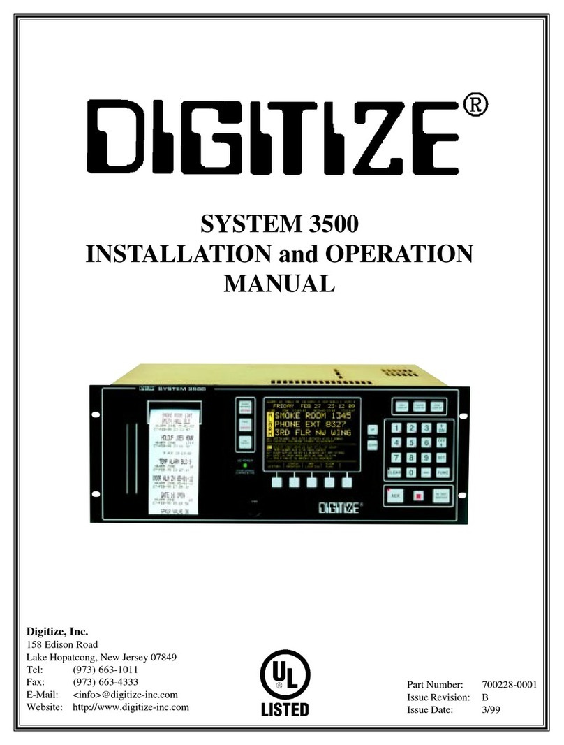
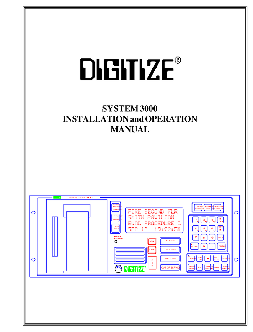
DIGITIZE System 3500 User manual

SYSTEM 3500 NETWORK CONTROLLER
INSTALLATION and OPERATION
MANUAL
Digitize, Inc.
158 Edison Road
Lake Hopatcong, New Jersey 07849
Tel: (973) 663-1011
Fax: (973) 663-4333
E-Mail: <info>@digitize-inc.com
Website: http://www.digitize-inc.com
Part Number: 700232-0001
Issue Revision: A
Issue Date: 02/00

TRADEMARKS
DIGITIZE (stylized) is a registered trademark of Digitize, Inc.
All of the above are trademarks of Digitize, Inc.
Any logos or product names mentioned in this document may be trademarks and are used for
identification purposes only.

PROPRIETARY NOTICE
AND DISCLAIMER
DIGITIZE, INC.
158 EDISON ROAD
LAKE HOPATCONG, NJ 07849
(973) 663-1011
FAX: (973) 663-4333
Website: http://www.digitize-inc.com
ThismanualhasbeenpreparedbyDIGITIZE,INC.forusebyitslicensees,distributorsandcustomers.
The information contained herein is the property of DIGITIZE, INC. and may not be copied, disclosed
or reproduced, in whole or in part, without the prior written approval of DIGITIZE, INC. Any
unauthorized disclosure to, or use of the enclosed information by, unauthorized third persons shall
void any and all representations, warranties and obligations on the part of DIGITIZE, INC.
DIGITIZE, INC. reserves the right to make changes to the specifications and material contained
herein without prior notice. The information and/or examples (including, but not limited to circuitry,
wiring diagrams, programming, the operation or use shown) described in this manual are intended
solely to illustrate the operating principles of the particular product. They are not a warranty,
representationorguaranteethataparticularexampleoruseshownwill perform in a particular situation.
They are given for illustration purposes only. DIGITIZE, INC. shall not be responsible, nor does it
represent, that any example of illustration will perform in a particular environment or practice unless
it specifically makes a representation to that effect.
The material set forth herein is for informational purposes only, and DIGITIZE, INC. assumes no
patent liability with respect to any information or illustrations contained herein.


FCC NOTICE
In compliance with Paragraph 15.105 of the FCC Rules and Regulations, the following notice is pro-
vided.
NOTE: This equipment has been tested and found to comply with the limits for a Class A digital
device, pursuant to Part 15 of the FCC Rules. These limits are designed to provide reasonable protec-
tion againste harmful interference when the equipment is operated in a commercial environment. This
equipment generates, uses, and can radiate radio frequency energy, and, if not installed and used in
accordance with the instruction manual, may cause interference to radio communications. Operation
of this equipment in a residential area is likely to cause interference, in which case the user will be
required to correct the interference at his own expense.
P/N 700120 Rev C


Table of Contents
SECTION 1 GENERAL INFORMATION
1.1. SYSTEM DESCRIPTION ........................................................................................................ 1-1
1.2. NETWORK CONTROLLER..................................................................................................... 1-1
1.3. DISPLAY (FIGURE 1)............................................................................................................ 1-2
1.4. MEMORY................................................................................................................................ 1-2
1.4.1. MEM-600 MEMORY CHIP.......................................................................................... 1-2
1.4.2. MBD-4800 MEMORY MOTHERBOARD .................................................................. 1-4
1.5. SPECIFICATIONS ..................................................................................................................... 1-4
1.5.1. ELECTRICAL ............................................................................................................... 1-4
1.5.2. FUSES ........................................................................................................................... 1-4
1.5.3. INPUTS ......................................................................................................................... 1-4
1.5.4. OUTPUTS ..................................................................................................................... 1-4
1.5.5. CONSTRUCTION......................................................................................................... 1-5
1.5.6. DIMENSIONS............................................................................................................... 1-5
1.5.7. WEIGHT........................................................................................................................ 1-5
1.5.8. TEMPERATURE AND HUMIDITY ............................................................................ 1-5
1.5.9. STRIP PRINTER ........................................................................................................... 1-5
1.5.10. DISPLAY ..................................................................................................................... 1-6
1.5.11. KEYPAD...................................................................................................................... 1-6
1.6 AUTOMATION PROTOCOLS............................................................................................... 1-6
1.7. FCC REQUIREMENTS............................................................................................................. 1-6
1.8. APPLICABLE PUBLICATIONS............................................................................................... 1-6
SECTION 2 INSTALLATION
2.1. HANDLING ............................................................................................................................... 2-1
2.1.1. PRECAUTIONS ............................................................................................................ 2-1
2.1.2. UNPACKING AND INSPECTION .............................................................................. 2-1
2.2. INSTALLATION PROCEDURE ............................................................................................... 2-1
2.3. WIRING ..................................................................................................................................... 2-1
2.3.2. FIELD WIRING ............................................................................................................ 2-1
SECTION 3 SYSTEM INITIALIZATION
3.1. GENERAL.................................................................................................................................. 3-1
3.2. ASSEMBLY ............................................................................................................................... 3-1
3.3. BATTERY INSTALLATION ..................................................................................................... 3-1
3.4. POWER-UP................................................................................................................................ 3-1
3.4.1. AC POWER................................................................................................................... 3-1

3.4.2. DC POWER................................................................................................................... 3-1
3.4.3. POWER TRANSFER .................................................................................................... 3-2
3.5. PROGRAM INITIALIZATION ................................................................................................. 3-2
3.6. CONNECTIONS AND SETTINGS........................................................................................... 3-3
SECTION 4 USER TEXT
4.1. USING THE EXTERNAL KEYBOARD .................................................................................. 4-1
4.1.1. GENERAL..................................................................................................................... 4-1
4.1.2. INITIAL SET-UP .......................................................................................................... 4-1
4.1.3. CONTROL & FUNCTION KEYS................................................................................ 4-1
4.1.4. ACCESS ........................................................................................................................ 4-2
4.2. EXTERNAL KEYBOARD MENU SELECTIONS .................................................................. 4-3
4.2.1. DIALER/STU MENU ................................................................................................... 4-3
4.2.1.1. ADDING TEXT TO A ZONE ...................................................................... 4-3
4.3. USER TEXT TYPES ................................................................................................................. 4-5
4.3.1. GENERIC ...................................................................................................................... 4-8
4.3.2. ZONE SPECIFIC........................................................................................................... 4-8
4.3.2.1. CHANGING ZONE TEXT ........................................................................... 4-9
4.3.2.2. DELETING ZONE TEXT............................................................................. 4-9
4.3.8. PASSWORD MENU ..................................................................................................... 4-10
4.3.9. EXIT DATA ENTRY MODE ........................................................................................ 4-11
4.3.10. TOTAL PAGES INSTALLED, USED, AND DELETED........................................... 4-11
SECTION 5 FRONT PANEL ACCESS
5.1. FRONT PANEL ACCESS, GENERAL..................................................................................... 5-1
5.2. FRONT PANEL MENUS........................................................................................................... 5-2
5.2.1. TIME MODE / TIME SET............................................................................................ 5-3
5.2.2. DAY / DATE / YEAR.................................................................................................... 5-3
5.2.3. ALARM LEVEL / TONE ............................................................................................. 5-4
5.2.4. THERMAL PRINTER INTENSITY............................................................................. 5-5
5.2.5. SERIAL PORT COMMUNICATIONS ......................................................................... 5-5
5.2.8. IN/OUT SERVICE PASSWORD YES/NO ................................................................... 5-6
5.2.8.1. CHANGING LEVEL DESCRIPTORS......................................................... 5-6
5.2.8.2. IN/OUT SERVICE PASSWORD .................................................................. 5-6
5.2.13. STATUS PRINTOUT SETUP MODE ........................................................................ 5-7
SECTION 6 OPERATION
6.1 CONTROLS ................................................................................................................................ 6-1
6.1.1. PAPER ADVANCE ....................................................................................................... 6-1
6.1.2. PRINT............................................................................................................................ 6-1
6.1.3. KEY SELECT ............................................................................................................... 6-1
6.1.5. DIALER LOOK UP....................................................................................................... 6-1

6.1.6. ZONE LOOK UP........................................................................................................... 6-2
6.1.7. NUMERIC KEYS.......................................................................................................... 6-2
6.1.8. CLEAR BUTTON ......................................................................................................... 6-2
6.1.9. HYPHEN (-) BUTTON ................................................................................................. 6-2
6.1.10. FUNC BUTTON.......................................................................................................... 6-2
6.1.11. SET BUTTON ............................................................................................................. 6-2
6.1.12. ON / - BUTTON ......................................................................................................... 6-3
6.1.13. OFF/ ¯ BUTTON....................................................................................................... 6-3
6.1.14. ACK BUTTON............................................................................................................ 6-3
6.1.15. IN/OUT SERVICE....................................................................................................... 6-3
6.1.16. SHIFT KEY ( ).......................................................................................................... 6-4
6.1.17. STATUS ....................................................................................................................... 6-4
6.1.18. REPORT KEY ............................................................................................................. 6-4
6.1.19 PROGRAMMABLE KEYS ....................................................................................... 6-4
6.1.19.1 HISTORY ................................................................................................... 6-5
6.1.19.2 NEXT PAGE HISTORY ............................................................................ 6-5
6.1.19.9. STATUS PRINTOUT................................................................................. 6-5
6.1.20. SCROLL KEYS ......................................................................................................... 6-5
6.1.20.1 RESTORE TO NORMAL QUE ................................................................ 6-5
6.1.20.2 BOTTOM OF ALARM QUE .................................................................... 6-5
6.1.20.3 MIDDLE OF ALARM QUE...................................................................... 6-5
6.1.20.4 TOP OF THE ALARM QUE..................................................................... 6-5
6.1.20.5 SNGL/MULTI PAGE DISP ....................................................................... 6-6
6.1.21. RESTART BUTTON................................................................................................... 6-6
6.1.22. KEYBOARD JACK .................................................................................................... 6-6
6.2. INDICATORS............................................................................................................................. 6-6
6.2.1. AC POWER................................................................................................................... 6-6
6.2.2. CONDITION INDICATOR........................................................................................ 6-6
6.2.3. CLEAR .......................................................................................................................... 6-6
6.2.4. ACK ............................................................................................................................... 6-6
6.2.5. ALARM INDICATOR................................................................................................... 6-7
6.3. OPERATING PROCEDURE ..................................................................................................... 6-7
6.3.1. PRIORITIES .................................................................................................................. 6-7
6.3.2. NORMAL QUIESCENT OPERATION........................................................................ 6-8
6.3.3. ALARM CONDITION.................................................................................................. 6-8
6.3.4. TROUBLE CONDITION.............................................................................................. 6-8
6.3.5. TAKING A ZONE TEMPORARILY OUT OF SERVICE ........................................... 6-9
6.3.7. INITIATING STATUS PRINTOUT FOR NON-SECURE ZONES ............................. 6-9
6.3.8. CHECKING STATUS/MESSAGE OF INDIVIDUAL ZONE ..................................... 6-9
6.3.10. CHANGING THE PAPER TAPE................................................................................ 6-9
6.3.11. SERIAL OUTPUT FROM THE SYSTEM 3500 NETWORK CONTROLLER ....... 6-10

SECTION 7 DERIVED CHANNEL NETWORK CONTROLLER
7.1 OVERVIEW ............................................................................................................................ 7-1
7.2 INITIALIZATION AND PORT SETTINGS........................................................................... 7-2
7.3 DERIVED CHANNEL SETUP SCREEN .............................................................................. 7-3
7.3.1 PASSWORD .................................................................................................................. 7-4
7.4 DERIVED CHANNEL STU AND GLOBAL SETTINGS..................................................... 7-4
7.4.1 GLOBAL SETTINGS ................................................................................................ 7-5
7.4.2 ADD/CHANGE/REMOVE STU ............................................................................... 7-5
7.5 DERIVED CHANNEL PROGRAMMABLE KEYS (FIGURE 7-1) ..................................... 7-7
7.5.1 STU CONTROL KEYS ............................................................................................. 7-7
7.5.2 STU INFO KEYS ....................................................................................................... 7-8
7.5.3 LIST/LOAD COMMANDS KEYS............................................................................ 7-8
SECTION 8 COMPUTER INTERFACE OPTIONS
8.1. OVERVIEW ............................................................................................................................ 8-1
8.2. CGRMS ................................................................................................................................... 8-1
8.3. CAPS ....................................................................................................................................... 8-1
8.3.1 CAPS DATA TRANSMISSION ................................................................................ 8-1
8.3.2 MESSAGE TYPE....................................................................................................... 8-1
8.3.3 TYPE NUMBER ........................................................................................................ 8-2
8.3.4 CONDITION .............................................................................................................. 8-2
8.4. CAPS PLUS............................................................................................................................. 8-2
SECTION 9 UPLOADING NEW SOFTWARE VERSIONS
9.1 OVERVIEW ............................................................................................................................... 9-1
9.2 UPLOADING FROM DISKETTE ............................................................................................ 9-1
8.2.1. SAVE COMMAND ...................................................................................................... 9-3
9.2.2. UPLOAD COMMAND ................................................................................................ 9-4
9.2.3. RUN COMMAND........................................................................................................ 9-5
APPENDIX A USER TEXT STEP-BY-STEP PROCEDURES ....................................A-1
APPENDIX B SYSTEM 3500 NETWORK CONTROLLER
SET MENUS STEP-BY-STEP PROCEDURES ...................................................... B- 1
APPENDIX C INSTALLATION DRAWINGS
SYSTEM 3500 NETWORK CONTROLLER........................................................... C-1

DIGITIZE, INC. 700232-A 02/00 1 - 1
Specifications Subject to Change Without Notice
NETWORK CONTROLLER INSTALLATION AND OPERATION MANUAL
SECTION 1
GENERAL INFORMATION
This manual provides the basic installation and operating procedures and instructions for the SYSTEM
3500 Network Controller. Illustrations are provided throughout to familiarize the operator with the
terminologyusedinthismanual. Operatorsandinstallersareadvisedtostudytheillustrationsandsystem
descriptions before reading the operating procedures. All installation and testing should be performed
by factory trained personnel.
1.1. SYSTEM DESCRIPTION
TheoverallsystemisknownastheAlarmProcessingSystem. Alarmsareprocessedfromalarm/
controlsensorsthroughalarm/control lines. Whenanalarm/control conditionoccurs,anaudible
alarm, indicator lamp, alphanumeric message display, and a printed hard copy record of the
alarm/control condition will be presented to the operating personnel. The system may be
comprised of single or multiple SYSTEM 3500 Network Controller’s. The system is designed
for fire alarm reporting, security alarm monitoring and control applications for the municipal,
industrial, military, healthcare, collegiate, and commercial sectors.
1.2. NETWORK CONTROLLER
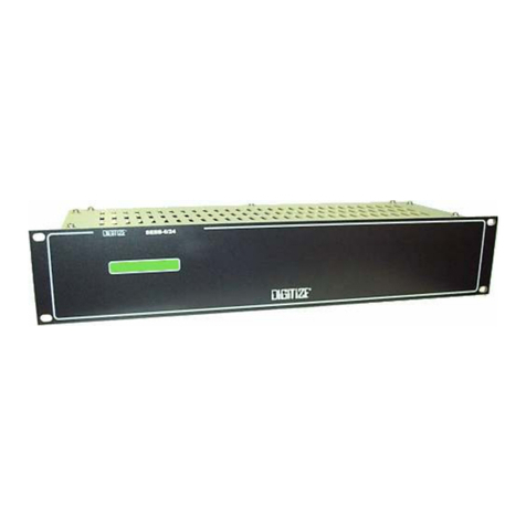
The overall unit is known as the SYSTEM 3500 Network Controller. The SYSTEM 3500
Network Controller is a totally solid state system that uses state of the art devices and circuitry
to continuously monitor and display the status of all system connected alarms. The SYSTEM
3500NetworkControllerisamicroprocessor-basedalarmmonitoringandcontrolunit,withfield
programmable, nonvolatile memory. The SYSTEM 3500 Network Controller may be used to
monitor multiplex, telegraph/McCulloh code, direct wire, digital dialer, network, addressable,
polling radio, and serial input alarm signals. The SYSTEM 3500 Network Controller will also
provide an alarm (both visual and/or audible) to operating personnel in the event of an internal
SYSTEM 3500 Network Controller malfunction. The basic unit is supplied with the following
standard equipment:
lPrinted circuit boards: POWER, DISP/KEY, CPU VI, E2PROM, PRT/KB, and I/O.
l150 Pages of field programmable memory for input of user text information.
lIntegral 20 column thermal printer capable of half, standard, and double height printing
in normal or bold intensity.
lFront panel mounted, 4.5 in. x 3.4 in., 1/4 VGA (320 x 240 pixel) electroluminescent
display screen capable of providing 160oviewing angle. Main alarm is readable at
distances of up to 20 feet.
lComputer style keyboard for user text entry as well as system setup.

1 - 2 DIGITIZE, INC. 700232-A 02/00
Specifications Subject to Change Without Notice
NETWORK CONTROLLER INSTALLATION AND OPERATION MANUAL
1.3. DISPLAY (FIGURE 1)
The SYSTEM 3500 Network Controller front panel display provides detailed information to the
operator. The first line indicates the current number of Alarms, Troubles, FA SUPV, Out of
Service and Restorals. The second line defaults to Day of Week, Month, Date and Time. If a
condition is received, the day of the week, condition and zone number appear.
The third line indicates the zone in alarm or trouble, the alarm priority level, the origination date
and time of the condition. During the system SET commands this line changes to the rotating
display message applicable to the SET command being processed.
The three lines of large text are the first page of the user text information for thelast condition.
The condition flashes along the left side of the three lines when it is received. After
acknowledgement, the condition stops flashing and remains illuminated. Additional pages of
user text appear in smaller type below the three lines of large text.
Below the double yellow line is space for a list of the current open conditions. The number of
conditions that appear here is dictated by the number of conditions received and the amount of
linesthat appear abovethe double yellowline. Forinstance, if thereare quite afewpages of user
textmessageslistedabovethedoubleyellowline,feweropenconditionsmaybedisplayedbelow
the double yellow line.
Thelastpartofthedisplayprovidesthetitlestotheprogrammablekeysoneachparticularsystem.
Their availability is determined by the options installed in each unit.
1.4. MEMORY
EachSYSTEM3500NetworkControllerissuppliedwith150screensofnonvolatile,nonmagnetic,
field programmable memory for storage of user text information. This memory is located in the
“system”memorymoduleandoccupiesthefirstICsocket,(U1)ofthefirstmemorymotherboard,
which is provided with the system. All memory module data will be maintained in the event of
a complete power failure, including the loss of battery backup. There are seven empty memory
sockets available on the system supplied memory motherboard. Nonvolatile, nonmagnetic
storage may be added to the SYSTEM 3500 Network Controller by installing memory modules
and additional motherboards. Each of these is explained below.
1.4.1. MEM-600 MEMORY CHIP
MEM-600 MEMORY CHIP P/N 450423-0002
INSTALLATION SHEET P/N 800360, sheet #3
Each MEM-600 provides storage for up to 600 screens of field programmable user text
messages,each screen consistingofthree lines of 16characters each. Each direct wirezone,
multiplexzone,digitaldialeraccountortelegraphboxcanhaveuptoninescreensofmemory
assigned to it.

DIGITIZE, INC. 700232-A 02/00 1 - 3
Specifications Subject to Change Without Notice
NETWORK CONTROLLER INSTALLATION AND OPERATION MANUAL
Figure 1 - NETWORK CONTROLLER DISPLAY

1 - 4 DIGITIZE, INC. 700232-A 02/00
Specifications Subject to Change Without Notice
NETWORK CONTROLLER INSTALLATION AND OPERATION MANUAL
1.4.2. MBD-4800 MEMORY MOTHERBOARD
MBD-4800, Full Memory Board P/N 400349-0004
MBD-EMPTY, Empty Memory Board P/N 400349-0002
Each MBD-EMPTY provides space for up to eight MEM-600 memory modules, or a total
of4800screens. TheMBD-4800containsall4800screens,andisinstalledinanyofthecard
slotsofthe SYSTEM 3500 Network Controller. Each MBD-4800 has a DIP switch to allow
you to set the address of the board. A total of eight motherboards may be installed in one
system. The number is limited only by the number of available card slots. A fully loaded
system can allow access to 37,950 field programmable user text screens.
1.5. SPECIFICATIONS
1.5.1. ELECTRICAL
Primary AC:
Power Input ............................................ 103-127 VAC / 207-253 VAC
Frequency Input......................................47-63 Hertz
Power Consumption ...............................50 Watts (max)
Standby DC:
Power Input ............................................24 VDC (nom)
Operating Current................................... 1 Ampere DC (max)
1.5.2. FUSES
AC line input fuse ........................................ 3.0 Amp. (fast-blow)
DC circuit breaker........................................ 5.0 Amp.
1.5.3. INPUTS
AC Power......................................................Detachable Cord
Standby Battery.............................................24 Volts D.C.
1.5.4. OUTPUTS
EXT. BUZZ: 12 Volt D.C., 0.1 A output for an external system failure buzzer.
AUDIO OUT: “Line”level output, (1 Volt P-P) identical to that of the front panel
speaker for connection to an external amplifier or P.A. system.

DIGITIZE, INC. 700232-A 02/00 1 - 5
Specifications Subject to Change Without Notice
NETWORK CONTROLLER INSTALLATION AND OPERATION MANUAL
1.5.5. CONSTRUCTION
The enclosure and cover of the SYSTEM 3500 Network Controller is made of 0.062"
aluminum. A membrane keypad is mounted on a 0.093" aluminum front panel.
1.5.6. DIMENSIONS
Height..................................................... 6.97" (17.7 cm)
Width ..................................................... 19.0" (48.3 cm)
Depth...................................................... 15.5" (39.5 cm)
1.5.7. WEIGHT
Net Weight ............................................. 21.3 lb. (9.7 Kg)
Shipping Weight .................................... 25.0 lb. (11.38 Kg)
1.5.8. TEMPERATURE AND HUMIDITY
The SYSTEM 3500 Network Controller operates best in an environment that is controlled
for the comfort of operating personnel, with respect to levels of temperature, humidity, and
dust content. The SYSTEM 3500 Network Controller will operate satisfactorily however,
within the range of environmental conditions listed below.
Operating Temperature .......................... 32 to 120ºF (0 to 49ºC)
Storage Temperature.............................. 14 to 158ºF (-10 to 70ºC)
Operating Humidity ............................... 0 to 85% (non-condensing)
Storage Humidity ................................... 0 to 100% (non-condensing)
1.5.9. STRIP PRINTER
Method ................................................... Thermal transfer
Speed...................................................... 2.0 Lines per Second
Print Head: Fixed head, 100 Dot array arranged in twenty (20) groups of five (5).
Characters:
Half height ....................................... 0.0625" (1.4mm)
Standard height................................ 0.125" (2.8mm)
Double height .................................. 0.25" (5.6mm)
Width ............................................... 0.08" (2.0mm)
Line Density .................................... 6 CPI
Columns per line ............................. 20
Set.................................................... ASCII-7 English
Paper:
Roll Size ......................................... 2.5"W x 165'L x 2.75"D (5.7cm x 50.4m x 7.0cm)
Color................................................ White
Print Image ..................................... Blue or black
Capacity.......................................... 1500 Alarms/roll

1 - 6 DIGITIZE, INC. 700232-A 02/00
Specifications Subject to Change Without Notice
NETWORK CONTROLLER INSTALLATION AND OPERATION MANUAL
1.5.10. DISPLAY
Format ....................................................320 x 240 pixels
Character Set..........................................96 character ASCII
Font ........................................................ English, General European
Font Size
Last Condition ................................. .24 in.
Date/Time........................................ .192 in.
All Other Text ................................. .094 in.
Color ...................................................... Neon Yellow
Mean Time Between Failure (MTBF) ...100,000+ Hours
Viewing Angle .......................................160 Degrees
Brightness .............................................. 30 ft -Lumens (min)
Viewing Area .........................................4.5 in wide x 3.4 in. high
1.5.11. KEYPAD
Thefrontpanelkeyboardisof“Mono-panel”design. Thekeyboardconsistsof32membrane
key switches, one of which has an embedded LED indicator. The push buttons have a life
expectancy rating in excess of 10 million actuations and will operate reliably throughout the
entireoperatingrangesspecifiedontheprecedingpages. Fiveofthe32keysareprogrammable
and are present based on the options installed.
1.6 AUTOMATION PROTOCOLS
The SYSTEM 3500 Network Controller utilizes the CAPS II protocol.
1.7. FCC REQUIREMENTS
The SYSTEM 3500 Network Controller complies with the limits set for a Class A computing
device as specified in Subpart J of Part 15 of the Federal Communications Commission “Rules
and Regulations”.
1.8. APPLICABLE PUBLICATIONS
lFCC “Rules and Regulations”, Part 15
lNational Electric Code
lNFPA 72 (Proprietary)

DIGITIZE, INC 700232-A 02/00 2 - 1
Specifications Subject to Change Without Notice
NETWORK CONTROLLER INSTALLATION AND OPERATION MANUAL
SECTION 2
INSTALLATION
2.1. HANDLING
2.1.1. PRECAUTIONS
CAUTION! : Do not touch internal circuitry during installation since static
discharge may damage components. If access to the interior of the unit is required,
follow the standard precautions set for handling CMOS circuitry.
2.1.2. UNPACKING AND INSPECTION
Before opening, inspect the shipping container for unusual damage. Then unpack the
contents and inspect for scratches, dents, or loose internal components. If your inspection
revealsanyphysicaldamage,retainthepackingmaterialandcontactthecarrierimmediately.
Each unit has been thoroughly inspected prior to shipment.
2.2. INSTALLATION PROCEDURE
TheSYSTEM3500 NetworkControllerisdesignedfor 19in. rackmountingandoccupiesseven
inches of vertical rack space. Each unit has four mounting holes located on the front panel and
is supplied with four special mounting washers in a small envelope attached to the front panel.
Mounting screws, regardless of size or thread type, must have a cone head shape (not flat head).
Mounting the SYSTEM 3500 Network Controller by way of the front panel will support itself
and all attachable options. No other supports are required.
2.3. WIRING
2.3.2. FIELD WIRING
All field wiring must be tested for grounds, induced or abnormal voltages, open and shorted
circuitconditions. Allfieldwiring must be free of these conditions prior to connecting them
to the SYSTEM 3500 Network Controller. Do not connect field wiring until the SYSTEM
3500 Network Controller has been fully tested beforehand. Tag all wiring for later
connection to the unit. Failure tocomplywiththese guidelines may cause damagetothe
unit.
Refer to the Appendix D, SYSTEM 3500 Network Controller Installation Drawing #800360
for electrical connections.

2 - 2 DIGITIZE, INC 700232-A 02/00
Specifications Subject to Change Without Notice
NETWORK CONTROLLER INSTALLATION AND OPERATION MANUAL

DIGITIZE, INC 700232-A 02/00 3 - 1
Specifications Subject to Change Without Notice
NETWORK CONTROLLER INSTALLATION AND OPERATION MANUAL
SECTION 3
SYSTEM INITIALIZATION
3.1. GENERAL
TofacilitatetheinitialsetupoftheSYSTEM3500NetworkController,thefollowingprocedures
should be performed in the order in which they appear.
3.2. ASSEMBLY
The SYSTEM 3500 Network Controller, itself, requires no assembly. Refer to the specific
sectionsofthismanualforadditionalassemblyrequirementstoconnecttheoptionssupplied.The
main unit should be started prior to connecting all options. Before connecting any power, first
check the voltage selector switch on the rear of the unit near the AC cord. It is set to 120VAC
from the factory. If this is correct, plug in the power cord and connect to a 120VAC dedicated
fire alarm branch circuit, labeled as such. Connect the branch circuit to a UL listed outlet box
with duplex outlets, rigidly mounted in the bottom, per installation requirements of the National
Electrical code and any local code. System 3500 is designed to be installed in a standard 19"
equipment rack.
3.3. BATTERY INSTALLATION
Thestandbypowerfor the SYSTEM 3500 Network Controller may be supplied by an externally
supplied 24 Volt DC source, (i.e., batteries and charger). This is to be connected after the unit
is operating on the AC source.
3.4. POWER-UP
To power up a SYSTEM 3500 Network Controller, primary AC can be applied first, then the
standby DC power may be applied.
3.4.1. AC POWER
To power-up the unit, move the AC power switch on the rear of the unit to the up position.
At this point the unit will start initializing.
3.4.2. DC POWER
After AC power has been applied, connect field-supplied external batteries and/or charger
(manufactured by others) to the 24 volt DC input terminals.
Referto Appendix D,SYSTEM3500 NetworkControllerInstallation Drawing #800360for
electrical connections.

3 - 2 DIGITIZE, INC 700232-A 02/00
Specifications Subject to Change Without Notice
NETWORK CONTROLLER INSTALLATION AND OPERATION MANUAL
3.4.3. POWER TRANSFER
If the AC power should fail for any reason, the unit will automatically transfer to standby
battery, the AC power lamp on the front panel will flash and the trouble signal will sound.
WhenACpowerisrestored,theunitwillautomaticallytransfertonormaloperation.TheAC
power lamp will remain ON and steady. AC failure and restoral will be annunciated and
printed.
3.5. PROGRAM INITIALIZATION
Uponpower-up, theSYSTEM3500 NetworkControllerwill momentarilydisplaythe following
screens, in sequence, while performing internal diagnostic tests:
Test CPU6
FLASH
checksums
U8
Awaiting Link
Kernel version 1.00
INITIALIZING
LOWER RAM PASSED
UPPER RAM PASSED
PRINTER CHECK # 2
LOWER RAM PASSED
Test CPU6 FLASH
U8: OK. U6: OK.
U7
Test CPU6 FLASH
U8: OK. U6: OK.
U7: OK.
Checking CPU6
INITIALIZING
LOWER RAM PASSED
UPPER RAM PASSED
LOWER RAM PASSED
UPPER RAM PASSED
PRINTER CHECK #3
LOWER RAM PASSED
UPPER RAM PASSED
PRINTER CHECK # 1
LOWER RAM PASSED
UPPER RAM PASSED
PRINTER CPU OK
Test CPU6
FLASH
checksums
Test CPU6
FLASH
U8: OK. U6
a. b. c.
d. e. f.
g. h. i.
j. k. l.
m. n.
Other manuals for System 3500
1
Table of contents
Other DIGITIZE Controllers manuals
Popular Controllers manuals by other brands

Spring
Spring V11 quick start guide

Festo
Festo SFC-LACI Brief overview

Carrier
Carrier OPN-OPT-OL Installation and startup guide

Rockwell Automation
Rockwell Automation Micro830 user manual

MATHERS CONTROLS
MATHERS CONTROLS MicroCommander installation instructions

Central Boiler
Central Boiler Fire Star XP owner's manual