Digitus Biometrics dbBioLock User manual

db BioLock / db ELock
/ db iCardLoc
k
Installation Manual

Model: db BioLock, db ELock, db iCardLock Digitus Biometrics, Inc. 2014
Page 2 of 11
Table of Contents
Determining which Lock Pawl to use................................................................................................3
Overview ................................................................................................................................4
Mounting the Door Interface Box - Step 1 .........................................................................................4
Mounting the Door Interface Box – Step 2 .........................................................................................5
Mounting the Door Lock – Step 3 ...................................................................................................6
Securing the Door Lock - Step 4.....................................................................................................7
Mount the tie-down pads to the Door and Cabinet – Step 6 ....................................................................8
Route the Cable between the lock and the Remote Node / Zero-U Controller – Step 7 .....................................9
Connect the cable to the Remote Node / Zero-U Controller – Step 8........................................................ 10

Model: db BioLock, db ELock, db iCardLock Digitus Biometrics, Inc. 2014
Page 3 of 11
Determining which Lock Pawl to use
•As all cabinets vary, we offer a wide range to pawls to suit the particular dimensions of your cabinet.
•If new pawls are required, there is a simple measurement that needs to be taken to determine which pawl you will
need. Using the existing mechanical lock, measure the length of “H” in millimeters (mm) as shown in figure 1. Using
“H” determine which pawl is required from Table 1.
•Once the correct pawl model has been determine, please contact our lock support team on +1 912 231 8175
Figure 1
Standard Pawl Pawl with Rod Control
H (mm) Model # H (mm) Model #
4 1000-112 4 1000-U63
6 1000-22 6 1000-U21
8 1000-113 8 1000-U64
10 1000-21 10 1000-U22
13 1000-20 13 1000-U23
14 1000-19 14 1000-U24
16 1000-18 16 1000-U25
18 1000-17 18 1000-U26
20 1000-16 20 1000-U27
22 1000-15 22 1000-U28
24 1000-14 24 1000-U29
25 1000-27 25 1000-U30
26 1000-50 26 1000-U31
28 1000-13 28 1000-U32
30 1000-28 30 1000-U33
32 1000-26 32 1000-U34
34 1000-12 34 1000-U35
35 1000-11 35 1000-U36
36 1000-51 36 1000-U37
38 1000-52 38 1000-U38
40 1000-25 40 1000-U39
42 1000-53 42 1000-U40
44 1000-54 44 1000-U41
45 1000-10 45 1000-U42
47 1000-55 47 1000-U43
50 1000-56 50 1000-U44
Table 1
In most situations the pawl from the existing mechanical handle can be re-used with the new lock.

Model: db BioLock, db ELock, db iCardLock Digitus Biometrics, Inc. 2014
Page 4 of 11
Overview
•If you are installing the lock into to a cabinet that already has a lock installed, remove the existing lock at this time.
•The "Door Interface Box" provides an interface between the Remote Node and the fingerprint scanner. It also
provides all power and signal connections to the electric lock.
•Install the Door Interface Box and electromechanical lock as show in Steps 3 thru 8.
Mounting the Door Interface Box - Step 1
•Before removing the double-sided high bond tape from the Door Interface Box, find a suitable location on the inside
of the cabinet door to mount the interface box.
•Ensure that the selected location will not affect the cabinet door from closing correctly.
•Note that for glass paneled cabinet doors with very narrow frames, the only suitable location may be on the glass.
•Once you’ve found a suitable location where you intend to mount the Door Interface Box, ensure that the door
surface is clean and free from any debris. (Using neat alcohol to clean the surface is highly recommended. Allow
drying time before proceeding.)
•Remove the protective cover from the double-sided high bond tape located along the edge of the Door Interface
Box.
Figure 3
For a db BioLock, follow the steps below. If you are installing a db ELock or db CardLock skip
straight to Step 4a.
Ensure that the interface box is located close enough to the lock opening in the door, so that the finger-sensor on the
ribbon cable can go through the door and connect into the lock, see Figure 5.

Model: db BioLock, db ELock, db iCardLock Digitus Biometrics, Inc. 2014
Page 5 of 11
Mounting the Door Interface Box – Step 2
•Attach the Door Interface Box to the inside door surface. Only apply a slight amount of pressure to the high bond
tape until you have ensured that the Door Interface Box will not prevent the cabinet door from closing.
•Once you have that the door will close properly and the finger sensor can attach to the lock, apply more pressure to
the high bond tape. The more pressure applied, the greater the bond.
Figure 4
Ensure that the Interface Box is located close enough to the lock opening in the door, so that the finger-sensor on the
ribbon cable can go through the door and connect into the lock, see Figure 5.

Model: db BioLock, db ELock, db iCardLock Digitus Biometrics, Inc. 2014
Page 6 of 11
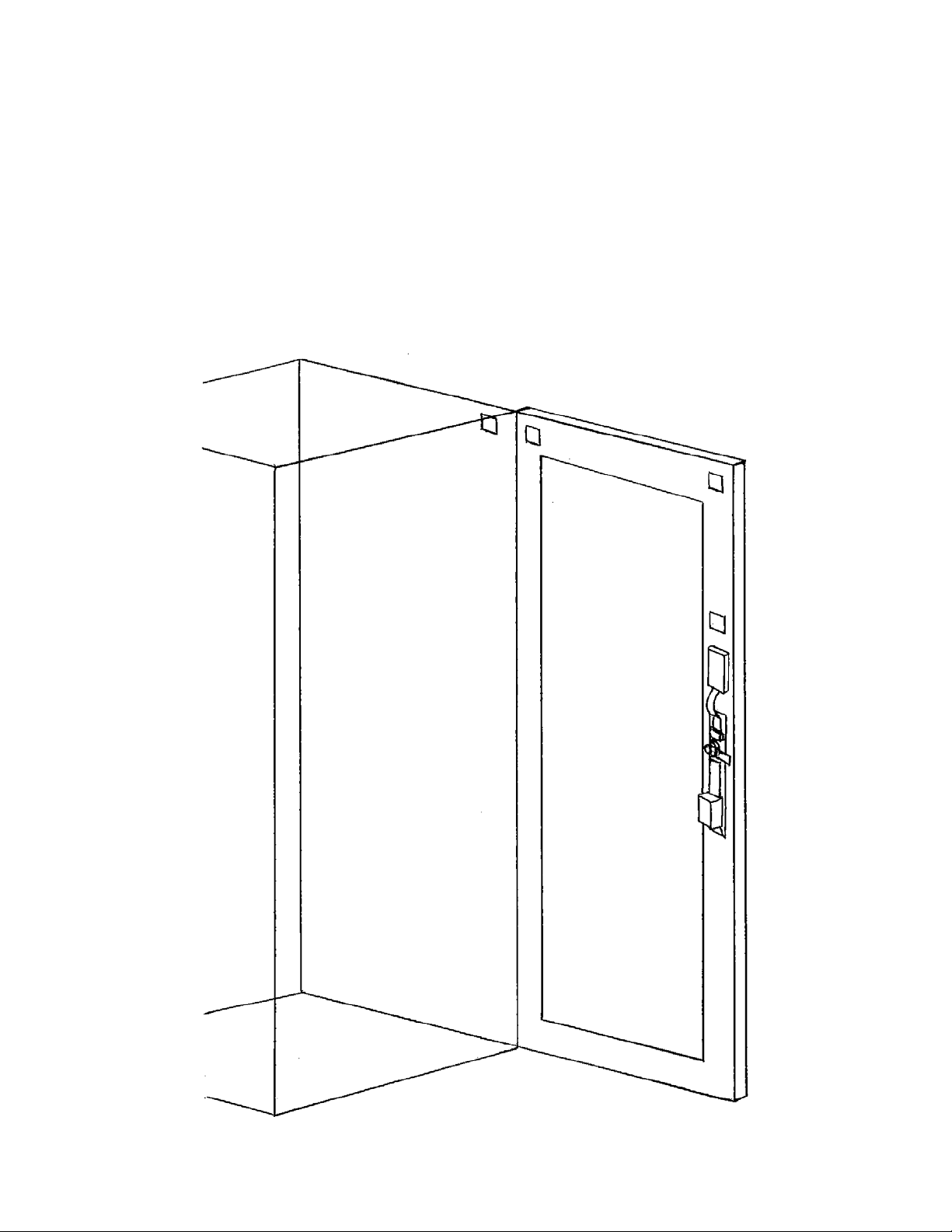
Mounting the Door Lock – Step 3
•Push the finger-sensor assembly through the door lock opening as shown in Figure 4 above.
•Attach the finger-sensor assembly into the back of the door lock as show in Figure 5.
•Situate the lock on the outside of the cabinet door so that the ribbon cable attached to the finger-sensor assembly is
at the top of the lock opening.
Figure 5 Figure 6
Note. When situating the lock through the hole in the cabinet door, the fit may be tight. Use gentle
force to push the lock into place

Model: db BioLock, db ELock, db iCardLock Digitus Biometrics, Inc. 2014
Page 7 of 11
Securing the Door Lock - Step 4
•Secure the lock to the door using the top mounting bracket and bottom mounting bracket as show in Figure 7a. Do
not over-tighten the screws in the bottom mounting bracket as this may jam the lock mechanism.
•For the db BioLock, connect the 8” cable from the back of the lock to the Door Interface Box. The cable will only
plug in one way.
•Page 3 of this document describes how to determine which pawl you will need, depending on the make and model
of cabinet.
•Pay particular attention to the rotation limiter. This is installed as shown depending on whether you have a right on
left hand opening door.
Pawl
Rotation Limiter
Figure 7
Note. Do not use an electric screwdriver to tighten the screws.
Model: db BioLock, db ELock, db iCardLock Digitus Biometrics, Inc. 2014
Page 8 of 11
Mount the tie-down pads to the Door and Cabinet – Step 6
•The ties down pads are used to secure the supplied 14’ cable that connects the Door Interface Box to the Remote
Node / Zero-U Controller for db BioLocks and connects the lock directly to the Remote Node / Zero-U Controller for
db Elocks and db CardLocks.
•Ensure that the door surface is clean and free from any debris. (Using neat alcohol to clean the surface is highly
recommended. Allow drying time before proceeding.)
•Remove the protective cover from each tie-down pad and situate as shown in Figure 9.
Figure 9

Model: db BioLock, db ELock, db iCardLock Digitus Biometrics, Inc. 2014
Page 9 of 11
Route the Cable between the lock and the Remote Node / Zero-U Controller – Step 7
•Route the supplied 12’ cable as show in Figure 10. Secure the cable to the tie-down pads using the supplied cable-
ties.
Figure 10

Model: db BioLock, db ELock, db iCardLock Digitus Biometrics, Inc. 2014
Page 10 of 11
Connect the cable to the Remote Node / Zero-U Controller – Step 8
Locks are connected to the Remote Node or Zero-U’s socket circled in the diagram below.
Each Remote Node / Zero-U Controller has two device inputs, Dev 1 and Dev 2.
Side View of Remote Node
It is recommended that for a cabinet with 2 doors, the front door is connected to Dev 1 and the back door is connected to
Dev 2.

Model: db BioLock, db ELock, db iCardLock Digitus Biometrics, Inc. 2014
Page 11 of 11
Digitus Biometrics, Inc.
2 East Bryan Street, Suite 502
Savannah, GA 31401 USA
Phone: 912-231-8175
Fax: 912.629.9478
www.digitus-biometrics.com
Specifications subject to change without notice.
This manual suits for next models
2
Table of contents
Other Digitus Biometrics Door Lock manuals


Popular Door Lock manuals by other brands

Schlage
Schlage COBRA MPM Installation instructions and user guide

Mandelli
Mandelli TG BOLT Assembly instructions

Abus
Abus HomeTec Pro CFA3000S manual

Chatsworth Products
Chatsworth Products ELS1500 installation instructions

Yale
Yale Real Living YRL210 Installation and programming instructions

WOOX
WOOX R7056 quick start guide


