Carbine CFB Series User manual

REFERENCE DIMENSIONS FOR CONCEALED SHORT LEVER INSTALLATION
The Next Generation in Locking
CFB-CSL FLIP BOLT MORTICE LOCK - CONCEALED SHORT LEVER
1. CONCEALED SHORT LEVER COMPONENT PART LIST
Item No. Description QTY
1 Drill Template 1
2 2.5mm T- Handle Allen Key 1
3 3mm Allen Key 1
4 Concealed Short Lever Faceplate 1
5 Slide Plate 1
6 Mounting Plate 1
7 Mounting Plate Clip 1
8 Mounting Boss 2
10 1
9 Mounting Screw
CSL Cam
2
LINE UP WITH SPINDLE
CTR LINE ON LOCK
DRILL
14 to 19
DRILL
9
DRILL
9
DRILL
9
19 X 33 LONG
SPINDLE
CTR LINE
EXTRUSION
THICKNESS
BACKSET
TOP
1
2
3
4
5
6 7 8 9
10
39
14
19
1
64 80
165
Drill 3 x Ø9 holes
Ø14 to 19
20 + DOOR EDGE
EXTRUSION
THICKNESS
Drill holes through
handle side only
DOOR EDGE
EXTRUSION
THICKNESS
Dimensions for lock cutouts,
refer to CFB-D / CFB-HB
installation instructions.
1
REFERENCE DIMENSIONS
Install Egress Handle using drilling template (next page)
Distributed in Australia by
LOCK AND KEY a division on the
DAVCOR GROUP PTY LTD ABN 95 003 562 598
This product has been manufactured in China
to Lock and Key Company specifications
This product is guaranteed to be free from defects in materials and
workmanship for a period of one (1) year from the date of original
purchase. This warranty is for replacement of product only and Lock
and Key Company does not accept responsibility for any direct or
consequential damage caused by this product or its use. This warranty
does not cover damage that results from faulty installation or usage,
alteration or modification of the product or tarnishing of the finish
including colour change due to weather, salt or chemical. Should this
product not perform satisfactorily in its intended application, return it
to place of purchase for replacement.
LOCK & KEY Phone: 1300 652 692 Web: www.locknkey.com.au Web: www. daveweb.com.au
NOTE
Please dispose of plastic
bags and other packaging
in a thoughtful manner
WARNING
Please keep contents
away from small children.
Suffocation Hazard.
Special Notes:
For lock installation instructions, please refer to installation instructions provided with CFB-D / CFB-HB.
For installation together with CLS-FAB - Flip Bolt Latching Strike, please refer to the installation instructions provided with CLS-FAB.
For installation together with CFB-OCEP - Oval Cylinder Rectangular Escutcheon, please refer to the installation instructions provided with CFB-OCEP.
LINE UP WITH SPINDLE
CTR LINE ON LOCK
FRONT FACE
SPINDLE
CTR LINE
DRILL
14
DRILL
8
DRILL
8

The Next Generation in Locking
CFB-CSL FLIP BOLT MORTICE LOCK - CONCEALED SHORT LEVER
2. DRILLING TEMPLATE INSTRUCTIONS
2A Insert lock into
door cavity.
ENSURE BOLT IS
EXTENDED.
2B Secure with
2x M4x16mm CSK
Screws (supplied
with lock).
LINE UP WITH SPINDLE
CTR LINE ON LOCK
DRILL
14 to 19
DRILL
9
DRILL
9
DRILL
9
19 X 33 LONG
SPINDLE
CTR LINE
EXTRUSION
THICKNESS
BACKSET
TOP
LINE UP WITH SPINDLE
CTR LINE ON LOCK
BACKSET
EXTRUSION
THICKNESS
TOP
DRILL
8
2C Insert drilling template
into cutout and against lock
face as shown.
Identify the colour that lines
up (closest) with the door
edge face.
2E Remove the 2x
M4x16mm CSK
Screws and lock
from the door.
2F Drill the following
holes as shown on the
diagram.
Clean up opening for
fitment of oval cylinder.
Drill Ø9 hole
Drill Ø19 holes
Drill Ø14 to 19 hole
Drill Ø9 holes
2G Preparation for installation of
concealed short lever furniture and
lock into metal door is now
complete.
Continue with concealed short lever
furniture installation instructions
section 3.
2D To determine the correct
backset position, align the
corresponding same coloured line
at the top and bottom, as shown
on the diagram.
Ensure template is straight.
To determine the vertical position
of the template, align the spindle
ctr line with the spindle line on the
lock
Mark drilling holes.
LINE UP WITH SPINDLE
CTR LINE ON LOCK
FRONT FACE
BACKSET
EXTRUSION
THICKNESS
TOP
DRILL
8
SPINDLE
CTR LINE
DRILL
14
DRILL
8
DRILL
8
LINE UP WITH SPINDLE
CTR LINE ON LOCK
DRILL
14 to 19
DRILL
9
DRILL
9
DRILL
9
19 X 33 LONG
SPINDLE
CTR LINE
EXTRUSION
THICKNESS
BACKSET
TOP
Spindle
Line

4. LEFT-HAND CONFIGURATION (FACTORY SUPPLIED)
The Next Generation in Locking
CFB-CSL FLIP BOLT MORTICE LOCK - CONCEALED SHORT LEVER
3A Insert mounting plate into door cavity,
do not drop inside door.
Firmly press mounting plate clip through
the door extrusion into the mounting plate.
3D Insert 1x mounting screw through
1x mounting boss and slide plate into the
top mounting plate hole and into lock.
Fasten to retain, do not tighten.
3E Insert 1x mounting screw through
1x mounting boss and slide plate into the
bottom mounting plate hole and into lock.
Fasten to retain, do not tighten.
3B Insert lock into door cavity.
ENSURE BOLT IS EXTENDED
3C Secure with 2x M4x16mm CSK
Screws (supplied with lock).
3F Align the slide plate to be even and parallel
with the door edge and tighten the mounting
screws.
3. INSTALLATION OF MAIN LOCK AND MOUNTING COMPONENTS
Ensure correct type of lock is used.
CFB-D - Flip Bolt Mortice Lock - Internal Deadlocking
or
CFB-HB - Flip Bolt Mortice Lock - Hold Back
4A Factory supplied.
Configured as left-hand door furniture.
4B Rotate the short lever into the up position.
The spring should be in the upper position as
shown on the diagram.
If no change of handing is required, skip to
step 6A for installation onto door.
If change of handing is required, continue to
step 5A.
Left-hand
Configuration
Spring Position
Lever Up

CFB-CSL FLIP BOLT MORTICE LOCK - CONCEALED SHORT LEVER
The Next Generation in Locking
Distributed in Australia by
LOCK AND KEY a division on the
DAVCOR GROUP PTY LTD ABN 95 003 562 598
This product has been manufactured in China
to Lock and Key Company specifications
This product is guaranteed to be free from defects in materials and
workmanship for a period of one (1) year from the date of original
purchase. This warranty is for replacement of product only and Lock
and Key Company does not accept responsibility for any direct or
consequential damage caused by this product or its use. This warranty
does not cover damage that results from faulty installation or usage,
alteration or modification of the product or tarnishing of the finish
including colour change due to weather, salt or chemical. Should this
product not perform satisfactorily in its intended application, return it
to place of purchase for replacement.
LOCK & KEY Phone: 1300 652 692 Web: www.locknkey.com.au Web: www. daveweb.com.au
NOTE
Please dispose of plastic
bags and other packaging
in a thoughtful manner
WARNING
Please keep contents
away from small children.
Suffocation Hazard.
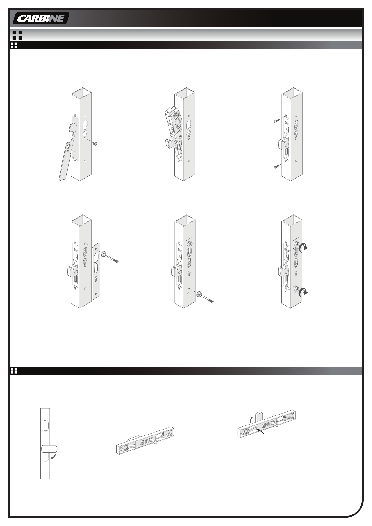
5C Rotate the short lever counter-clockwise
90° as shown on the diagram.
5D Whilst spring is as shown, replace short
lever back into door furniture and securely
re-fasten the central handle mounting screw.
5E Test the short lever rotation to ensure the
position is in right-hand configuration.
5F Rotate the short lever counter-clock-
wise 90° into the downward position as
shown on the diagram.
5A Remove central handle mounting
screw using supplied 3mm allen key.
5B Remove short lever together with
nylon bearing washer and hub.
Ensure parts are kept assembled together.
6. INSTALLATION OF CONCEALED SHORT LEVER
6D Insert oval key cylinder
with CSL cam and secure
with retainer pin.
Check retainer pin is flush
with lock body.
Insert oval key
cylinder and
retainer pin
if required.
6E Insert oval key cylinder
and secure retainer pin if
required.**
Attach cover plate to lock
and secure with
2x M4x6mm CSK Screws.
**With rabbit ear / R cam fitted on
the oval cylinder.
6F Installation is now complete.
6B Whilst keeping the
furniture flush with the slide
plate, insert the supplied
2.5mm T-handle allen key
into the grub screw inside
the top of the cylinder hole.
Rotate the grub screw
clockwise until tight, sliding
the faceplate downwards
into its fitted position.
Remove allen key
afterwards.
Test lever operation.
Spring Position
Spring Position Spring Position
Lever Down
Right-hand
Configuration
6A Ensure short lever
is in the horizontal
position and the lock
bolt is extended.
Position the faceplate to
the door and insert the
spindle into the lock
drive and the faceplate
over the mounting
bosses.
Ensure lock bolt is extended
Mounting Boss
Mounting Boss
6C Attach CSL cam to oval
key cylinder.
Special Notes:
For lock installation instructions, please refer to installation instructions provided with CFB-D / CFB-HB.
For installation together with CLS-FAB - Flip Bolt Latching Strike, please refer to the installation instructions provided with CLS-FAB.
For installation together with CFB-OCEP - Oval Cylinder Rectangular Escutcheon, please refer to the installation instructions provided with CFB-OCEP.
5. CHANGE OF HANDING TO RIGHT-HAND CONFIGURATION
This manual suits for next models
5
Other Carbine Door Lock manuals