manuals.online logo
Brands
  1. Home
  2. •
  3. Brands
  4. •
  5. Schlage
  6. •
  7. Door Lock
  8. •
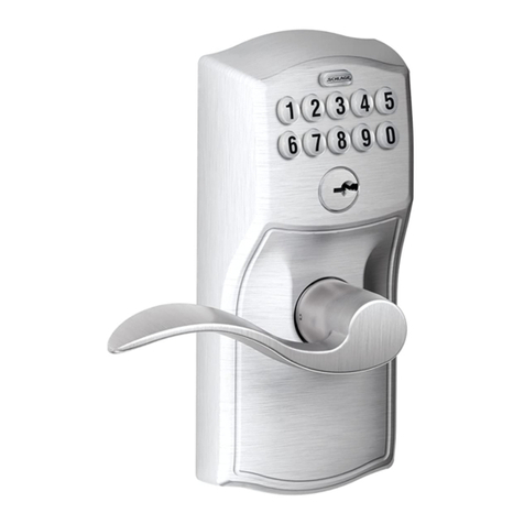
  9. Schlage COBRA MPM Mounting instructions

Schlage COBRA MPM Mounting instructions

Inst allation Instructions and Users Manual
MMPPMM
&&
MMPPMMAA
MORTISE LOCKING SYSTEM
FORM 57018 Rev. B 02-10-2005
AUTOBOLT
LATCHBOLT
MMPPMMMMPPMMAA
Manually Progammed Mortise
Lockset. Up to 100 codes can be
manually programmed.
SCHLAGE COBRA MPM
FORM 57018 Rev. B 02-10-2005PAGE 2
Use the paper template or information below to prep door, latch and frame. Dimensions are in
inches.
1. PREP DOOR & FRAME FOR LOCK:
DOOR PREP FOR
COBRA SPM/MPM
ALL HOLES ARE THRU
INSTALLATION INSTRUCTIONS SCHLAGE COBRA MPM
FORM 57018 Rev. B 02-10-2005PAGE 3
NOTE: The locks are shipped as ordered from factory. If it is
necessary to change the hand of the lock, follow the steps
below:
TO CHANGE HAND OF LOCK CASE:
A. With bolt fully extended, insert change pin (included in the
hardware pack) into hole. (It will snap over a groove on the
main shaft, holding it in place.)
B. Remove set screw in bolt so bolt can be removed.
C. Rotate bolt and reinstall on to shaft. Do not remove spring.
D. Apply thread locking compound to set screw.
Loctite 242 recommended.
E. Install and tighten set screw (from other side, as shown).
F. Remove change pin.
5/32” SOCKET CAP SCREW
LOCTITE 242 RECOMMENDED
OUTSIDE ESCUTCHEON
OUTSIDE HANDLE
CHANGE PIN
LOCK CASE
BOLT
(AUTOBOLT SHOWN)
TO CHANGE HAND OF LEVERS:
A. Loosen 5/32” socket cap screw and remove lever.
B. Rotate handle to opposite position.
C. Apply thread locker to screw. Loctite 242 recommended.
D. Reinstall handle.
E. Repeat for inside escutcheon (not shown).
A
B
C
E
D
F
2. CHANGE LOCK HAND (IF NECESSARY):
INSTALLATION INSTRUCTIONS SCHLAGE COBRA MPM
FORM 57018 Rev. B 02-10-2005PAGE 4
4. INSTALL STRIKE:
3. INSTALL MORTISE LOCK:
STRIKE BOX
STRIKE
STRIKE SUPPLIED WITH PROCUCT MUST BE USED FOR
PROPER OPERATION.
INSTALLATION INSTRUCTIONS SCHLAGE COBRA MPM
FORM 57018 Rev. B 02-10-2005PAGE 5
6. INSTALL INSIDE BASEPLATE ASSEMBLY:
7. INSTALL 6- or 7-PIN IC CORE CYLINDER
(RECOMMENDED):
A. HOLD LOCK IN HORIZONTAL
POSITION AS SHOWN AND PUSH
PLUG IN UNTIL PIN FALLS OUT.
REMOVE PLUG.
B. INSERT CYLINDER CON-
TROL KEY INTO CORE AND
TURN CLOCKWISE TO
RETRACT LOCKING PIN.
C. PUSH CYLINDER CORE
INTO LOCK - RESISTANCE
WILL BE NOTICEABLE.
TURN KEY COUNTER-
CLOCKWISE TO ENGAGE
LOCKING PIN.
D. REMOVE KEY.
LOCK IS NOW
OPERATIONAL.
OPERATION:
EITHER THE CYLINDER PLUG
OR THE IC CORE MUST BE
INSTALLED FOR THE LOCK
TO OPERATE. REMOVAL OF
THE CORE OR PLUG AUTO-
MATICALLY UNLOCKS THE
LOCK. IT IS RECOMMENDED
THAT AN IC CORE BE
INSTALLED IN CASE IT EVER
BECOMES NECESSARY TO
UNLOCK THE LOCK USING
MECHANICAL MEANS.
REMOVE TAPE
(IF PRESENT)
NOTE:
6-PIN IC CORE CYLINDERS
REQUIRE THAT THE
ADAPTER IS INSTALLED TO
MAKE THEM AS LONG AS A 7-
PIN CYLINDER. THE ADAPTER
IS INCLUDED IN THE SCREW
PACK. DO NOT INSTALL THE
ADAPTER IN A 7-PIN IC CORE
CYLINDER.
5. INSTALL OUTSIDE SPINDLE &
ESCUTCHEON:
INSTALLATION INSTRUCTIONS SCHLAGE COBRA MPM
FORM 57018 Rev. B 02-10-2005PAGE 6
8. MAKE WIRING HARNESS CONNECTIONS:
10. INSTALL ARMOR FRONT:
9. INSTALL INSIDE SPINDLE/SPRING
AND INSIDE ESCUTCHEON:
PLUG CONNECTORS
TOGETHER
PROGRAM LOCK CODES:
11
Code Functions:
The MPC Cobra is manually programmable to have up to 100 codes. The codes can have different functions as
described below. Several types of functions have factory default values which are operational as soon as the lock is
installed. It is highly recommended that the Programming Code be changed (this will delete all factory default codes)
and new codes be added. In addition, it is recommended that at least one Freeze/Lockout Code be added - in case
the batteries get completely drained. (See “Battery Information” on below.) All codes can be 3-8 digits in length
(except the Programming code which must be 5-8 digits.) Keep a log of all issued codes. Issue codes exclusively with
all odd or all even numbers - this practice will make it easier to spot duplicate codes, since each keypad button repre-
sents two numbers (for example, code 246 is identical to code 135.)
FUNCTION: FACTORY DEFAULT: DESCRIPTION:
PROGRAMMING
NORMAL
9 7 5 3 1
1 3 5 7 9
1 3 5 1 3 5
9 1 1 5
NONE
NONE
NONE
TOGGLE
ONE USE
SUPERVISED
PASS THRU
FREEZE/LOCKOUT
The programming code puts the lock into a programming mode. It will
not unlock the lock. When a Programming code plus “*” is entered the
LEDs alternately flash several times indicating the lock is in a program-
ming mode. If more than 30 seconds pass in between programming
entries, the lock returns to a normal operational state.
Normal codes unlock the lock for the relock time delay. While the lock is
unlocked the green LED will flash. The LED will stop flashing and the
lock will relock.
Toggle codes unlock the lock indefinitely. When the same (or another)
toggle code is entered, the lock will immediately relock. When a toggle
code is entered, the green LED will flash once. The LED will stop flash-
ing and the lock will relock. .
Freeze/Lockout codes prevent other codes from working. The lock can
be locked or unlocked when one is entered. If it is locked, a Pass Thru
code will unlock it but all other codes will not. Only another Lockout code
will reverse the effect.
One Use codes unlock the lock for the relock time delay. They will only
work once and then are deleted from memory. They can used again if
they are programmed (added) into memory again.
Supervised codes require that two different supervised codes entered in
order to unlock the lock for the relock time delay.
Pass Thru codes will unlock the door for the relock time delay even if
the door is in the lockout mode.
BATTERY INFORMATION:
The MPC Cobra uses four, standard AA batter-
ies. The batteries should provide enough life for
approximately 80,000 lock/unlock cycles. When
the batteries are running out the lock provides
two different modes of low battery indication:
First, when a code is entered, the red LED will
flash twelve times before the lock executes the
command of the code. This is an indication that
it is time to replace the batteries. The lock will
go for about 500 cycles in this condition. After it
reaches a certain point the lock will go into “Low
Battery Lockout” mode. A Freeze/Lockout code
will need to be entered in order gain access. If
the batteries are not changed, the lock will even-
tually not work and manual key override (if
installed) will need to be used.
CLEARING MEMORY:
Clearing memory will delete all programmed codes and restore
factory default codes. If the memory ever needs to be erased fol-
low the steps below:
1. Remove the inside escutcheon. Remove one of the batteries.
2. Press any key.
3. Hold down the “*” key and reinstall the battery. Continue holding
the “*” key down. The red LED will flash a few times and then stay
on.
4. Release the “*” key.
5. Install the inside escutcheon.
Note: to return the lock to the factory default relock time delay, do
steps 1-4 twice in a row.
FORM 57018 Rev. B 02-10-2005PAGE 7
INSTALLATION INSTRUCTIONS SCHLAGE COBRA MPM
FORM 57018 Rev. B 02-10-2005PAGE 8
PROGRAMMING STEPS:
7
TO CHANGE
PROGRAMMING CODE
ENTER PROG. CODE
ENTER NEW
PROG.CODE
ENTER NEW
PROG.CODE AGAIN
*
*
*
*
33
TO ADD
TOGGLE CODE
ENTER PROG. CODE
ENTER NEW CODE
TO ADD MORE
TO END
*
*
191 *
*
*
*
33
TO ADD
FREEZE/LOCKOUT CODE
ENTER PROG. CODE
ENTER NEW CODE
TO ADD MORE
TO END
*
*
115 *
*
*
*
33
TO ADD
ONE TIME USE CODE
ENTER PROG. CODE
ENTER NEW CODE
TO ADD MORE
TO END
*
*
113 *
*
*
*
99
TO CHANGE RELOCK
TIME DELAY (DEFAULT 5 SEC.)
ENTER PROG. CODE
TO END
*
*
*
*
33
TO ADD
SUPERVISED CODE
ENTER PROG. CODE
ENTER NEW CODE
TO ADD MORE
TO END
*
*
117 *
*
*
*
33
TO ADD
PASS THRU CODE
ENTER PROG. CODE
ENTER NEW CODE
TO ADD MORE
TO END
*
*
119 *
*
*
*
TO ADD
NORMAL USE CODE
ENTER PROG. CODE
ENTER NEW CODE
TO ADD MORE
TO END
*
*
*
*
*
3
1
1
5
TO DELETE
CODES
ENTER PROG. CODE
ENTER CODE
TO DELETE MORE
TO END
*
*
*
*
*
5
PRESS 1 FOR 1
SEC. AND/OR 5
FOR 5 SEC. THE
TIMES WILL ADD.
Use the steps on this page
to program codes into the
lock. The “*” key is used
like the <ENTER> key is on
a computer. After pressing
the “*” key, wait for the red
and green LEDs to stop
flashing before proceeding
to the next step. If at any
time the red LED stays on
while the green LED flash-
es an error has occurred.
The flashing message will
repeat three times. Count
the number of flashes and
consult the error code chart
below.
FLASHES ERROR CODE DESCRIPTION
2 Code too long
Maximum digits
6 • 12 button keypad
8 • 6 button keypad
3 Memory full, delete some codes
4 Use Change Prog. code procedure
5 Prog. Code entries do not match,
code not changed
6 Invalid entry, start over
7 Code for deletion not found
8 Code too short
Prog. code 5 digit minimum
User Code 3 digit minimum
9 Duplicate code

This manual suits for next models

1

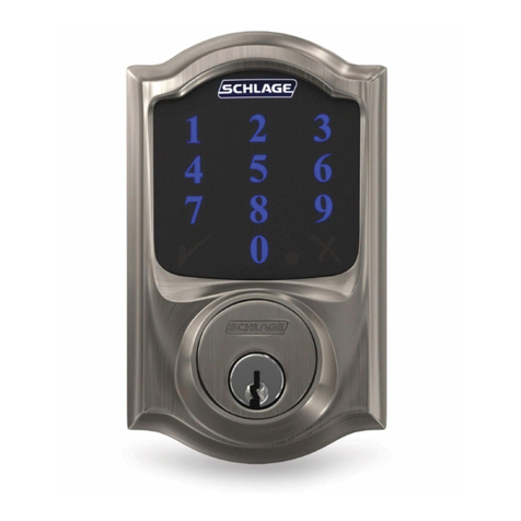
Other Schlage Door Lock manuals

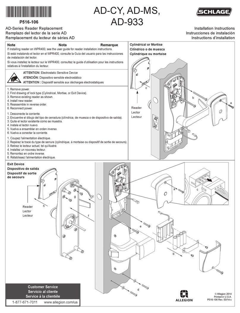
Schlage AL-SERIES User manual

Schlage

Schlage AL-SERIES User manual

Schlage CONNECT User manual

Schlage

Schlage CONNECT User manual

Schlage CO-250 User manual

Schlage

Schlage CO-250 User manual

Schlage D-Series User manual

Schlage

Schlage D-Series User manual

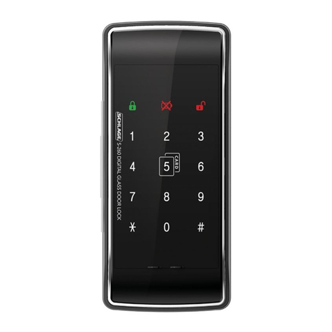
Schlage S-260 User manual

Schlage

Schlage S-260 User manual

Schlage AD-200-CY User manual

Schlage

Schlage AD-200-CY User manual

Schlage BE365 User manual

Schlage

Schlage BE365 User manual

Schlage AD-Series User manual

Schlage

Schlage AD-Series User manual

Schlage Accents BA-362 User manual

Schlage

Schlage Accents BA-362 User manual

Schlage L9000 Series User manual

Schlage

Schlage L9000 Series User manual

Schlage BE469 User manual

Schlage

Schlage BE469 User manual

Schlage BE468 series User manual

Schlage

Schlage BE468 series User manual

Schlage S-5600 User manual

Schlage

Schlage S-5600 User manual

Schlage BE365 User manual

Schlage

Schlage BE365 User manual

Schlage AD-250 User manual

Schlage

Schlage AD-250 User manual

Schlage Custom FC21 User manual

Schlage

Schlage Custom FC21 User manual

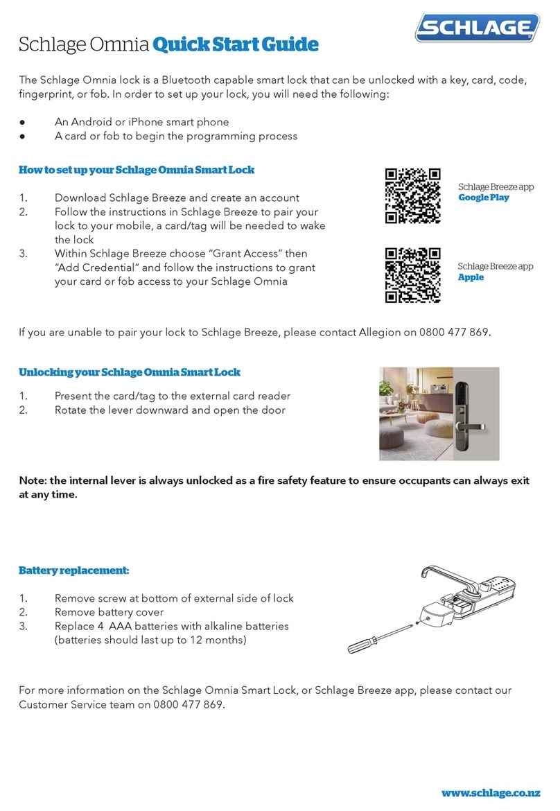
Schlage SENSE User manual

Schlage

Schlage SENSE User manual

Schlage LT Series User manual

Schlage

Schlage LT Series User manual

Schlage Connect BE469ZP User manual

Schlage

Schlage Connect BE469ZP User manual

Schlage Connect Smart Deadbolt User manual

Schlage

Schlage Connect Smart Deadbolt User manual

Schlage KC9000-LG User manual

Schlage

Schlage KC9000-LG User manual

Schlage KING COBRA KC5196-R Manual

Schlage

Schlage KING COBRA KC5196-R Manual

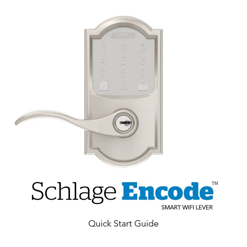
Schlage Encode User manual

Schlage

Schlage Encode User manual

Schlage CO-993 User manual

Schlage

Schlage CO-993 User manual

Popular Door Lock manuals by other brands

EloStar 7215 operating instructions

EloStar

EloStar 7215 operating instructions

CODELOCKS CL610 Guide

CODELOCKS

CODELOCKS CL610 Guide

Salto XS4 Mini installation guide

Salto

Salto XS4 Mini installation guide

Sygonix 20812V operating instructions

Sygonix

Sygonix 20812V operating instructions

KFV AS 2 Series Cleaning and maintenance instructions

KFV

KFV AS 2 Series Cleaning and maintenance instructions

Assa Abloy mFlipLock standard Assembly and operating instructions

Assa Abloy

Assa Abloy mFlipLock standard Assembly and operating instructions

Kaba Ilco 790/79 Series Rework Installation Sheet

Kaba

Kaba Ilco 790/79 Series Rework Installation Sheet

Allegion FALCON 25-V installation instructions

Allegion

Allegion FALCON 25-V installation instructions

SECO-LARM E-942FC-1300 installation manual

SECO-LARM

SECO-LARM E-942FC-1300 installation manual

Simons Voss Technologies WaveNet Lock-Node SH 3062 quick guide

Simons Voss Technologies

Simons Voss Technologies WaveNet Lock-Node SH 3062 quick guide

Yale 4600CL Series installation instructions

Yale

Yale 4600CL Series installation instructions

Lock LAL4701 Installation instructions and template

Lock

Lock LAL4701 Installation instructions and template

Assa Abloy IKON eCLIQ SPARK N112 User instructions

Assa Abloy

Assa Abloy IKON eCLIQ SPARK N112 User instructions

Hans Grohe PuraVida Instructions for use/assembly instructions

Hans Grohe

Hans Grohe PuraVida Instructions for use/assembly instructions

SECO-LARM SD-995C-LE25 manual

SECO-LARM

SECO-LARM SD-995C-LE25 manual

Assa Abloy Sargent 6-Line installation instructions

Assa Abloy

Assa Abloy Sargent 6-Line installation instructions

Salto Comfort E1CD0x00fft installation guide

Salto

Salto Comfort E1CD0x00fft installation guide

AYR int_LOCK BT user manual

AYR

AYR int_LOCK BT user manual

manuals.online logo
manuals.online logoBrands
  • About & Mission
  • Contact us
  • Privacy Policy
  • Terms and Conditions

Copyright 2025 Manuals.Online. All Rights Reserved.