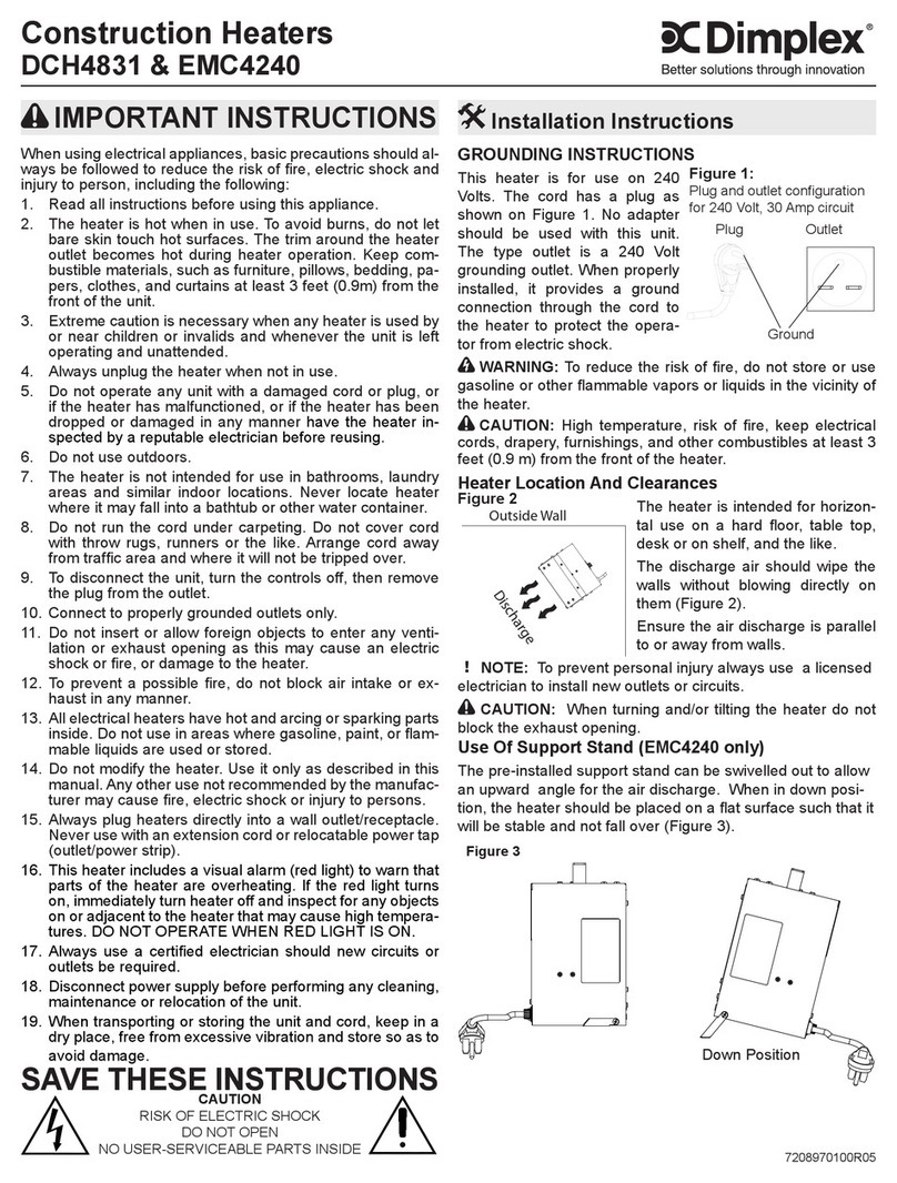
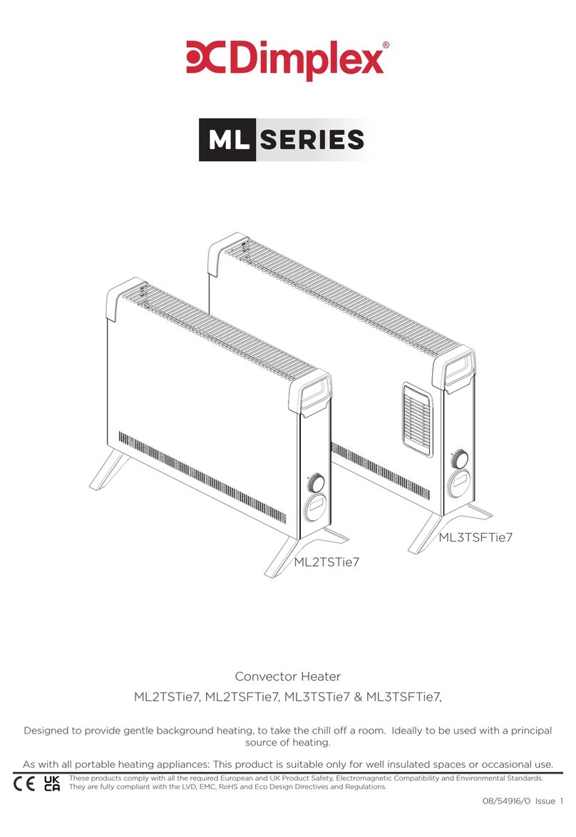
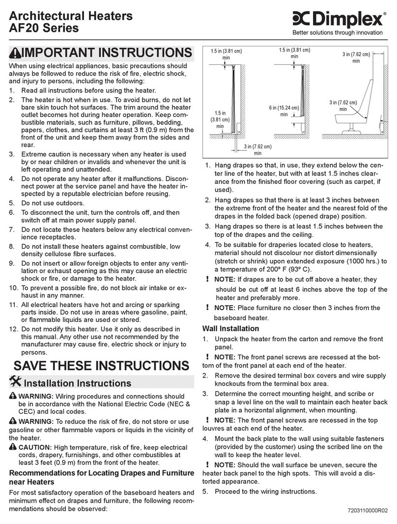
IMPORTANT:THESEINSTRUCTIONSSHOULDBEREADCAREFULLYANDRETAINEDFORFUTUREREFERENCE
IMPORTANT SAFETY ADVICE
DONOTCOVER OR OBSTRUCTthe air inletoroutlet grille.
ENSURETHEAPPLIANCEISEARTHED.
Donot usethis heaterin areas whereexcessive dustexists.
Do not use this heater with young children unattended.
This appliance is not intended for use by children or other
persons without assistance or supervision if their physical,
sensory or mental capabilities prevent them from using it
safely. Children should be supervised to ensure that they
do not play with the appliance.
The heater carries the Warning symbol indicating that
it must not be covered.
Warning: In order to avoid overheating, do not cover the
heater.
Thisheater mustnotbe locatedimmediatelyabove orbelow
a fixed socket outlet or connection box.
Always disconnect supply before working on the product.
Thisappliance shouldonly beconnected tothe fixed wiring
of the premises by means of conduit.
This product should be mounted safely to solid wall, floor
or ceiling surfaces only.
If mounting the appliance horizontally it should not be
mounted less than 1.8m from the floor.
This product must not be subjected to water spray or
immersion.
Ensure the supply cables are of adequate current carrying
capacity and are protected by a suitable fuse.
This appliance should not be mounted in a toilet or
washroom.
Ensure proper manual handling procedures are observed
at all times.
WARNING: Isolate electrical supply to ALLmodular linked
units when carrying out maintenance.
Models
Electrical
The installation of this appliance should be carried out by a
competent electrician and be in accordance with the current IEE
wiring regulations.
Architectural Air Curtains
Models :ARC10E,ARC15E,ARC20E,ARC10W,ARC15W,ARC20W, ARC10A, ARC15A & ARC20A
Fixing Positions
This appliance may be either fixed to a ceiling - see Fig. 1 or floor
mounted see Fig. 2 using an appropriate foot.
A minimum distance of 500mm is required from top of the
appliancetothe ceiling(see Fig. 1) andalso thedistance between
the bottom of the appliance and the top of the door should be
kept to a minimum (see ‘C’ in Fig. 1).
To open the appliance, remove the inlet grilles (‘x’ in Fig. 3)
Remove the front panel (‘z’ in Fig. 3).
Horizontal Mounting
By using the fixing holes in the top of the air curtain, attachment
to a ceiling over the product can be achieved using suitable M10
threaded steel rod or similar supports of sufficient strength -
see ‘s’ in Fig. 1.
Vertical Mounting
The architectural range of air curtains can be vertically mounted
using a suitable floor foot (Ref: ARCVMF). Contact Dimplex or
yourserviceagent forfurther information. Refer toFig. 2 for fixing
details.
Electrical connection
All products are fitted with a microprocessor control. Electrical
power and control connections are made as shown in Fig. 6 & 7.
A suitable local isolating switch must be provided in the electrical
supply circuit with at least 3mm clearance on each pole. In
order to access the electrical connections, remove the inlet grilles
(see ‘x’ in Fig. 3). Remove the front panel (see ‘z’ in Fig. 3) and
also remove the mains cover plate (see ‘y’ in Fig. 3).
ARC Electric Models
Feed an appropriate supply cable as shown in Fig. 4 and attach
to the terminal block (see ‘a’ in Fig. 4).
Note: Ensure that cables are secured to the cable tray with fixing
ties to avoid contact with the elements.
ARC Water/Ambient Models
Feed an appropriate supply cable as shown in Fig. 5 and attach
to the terminal block (see ‘a’ in Fig. 5).
A suitable cable for a switch panel (kit ref. - CABC1 for electrically
heated models or CABC2 for water heated/ambient models)
can be similarly introduced through the top panel and connected
to the circuit board.
If the unit is to be operated in conjunction with a door switch, a
normally closed switch should be wired (see ‘D’ in Fig. 6 & 7) as
appropriate - see also ‘Switch Panel Instructions’.
If the unit is to be connected to a Building Energy Management
System, connections to be made (see ‘G’ in Fig. 6 & 7) as
appropriate.
Ensure that the air curtain is securely fastened in position and
that the supply cables are firmly clamped before operating the
appliance.
Water connection
Models designed for use in conjunction with a low pressure hot
water supply should be individually connected (in a parallel
circuit) to the flow and return pipe-work.
Connections (see ‘a’ in Fig. 8) are ¾” BSPT and isolation valves
(see ‘b’ in Fig. 8) should be fitted as close to the air curtain
connection points as possible. Care should be taken to release
as much air as possible to prevent air locks.
Maximum water supply conditions are 100ºC and 10 bar
(1.03MPa).
AMBIENT
ARC10A n/a 220-240V~1PN 1.5 55 3.75
ARC15A n/a 220-240V~1PN 2.3 82.5 3.75
ARC20A n/a 220-240V~1PN 3.0 110 3.75
ELECTRICALLYHEATED
ARC10E 6.0 / 12.0 380-415V~3PN 18 60 3.75
ARC15E 9.0 / 18.0 380-415V~3PN 27 90 3.75
ARC20E 12.0 / 24.0 380-415V~3PN 36 120 3.75
WATER HEATED (at 82/71 °C - LPHW)**
ARC10W 12 220-240V~1PN 1.5 65 3.75
ARC15W 18 220-240V~1PN 2.3 95 3.75
ARC20W 24 220-240V~1PN 3 130 3.75
Model Heat
output
kW
Electrical
Supply Electrical
load
(per phase)
A
Weight
kg
Recom-
mended
height
m
