manuals.online logo
Brands
  1. Home
  2. •
  3. Brands
  4. •
  5. Dimplex
  6. •
  7. Heater
  8. •
  9. Dimplex HCT 300 Service manual

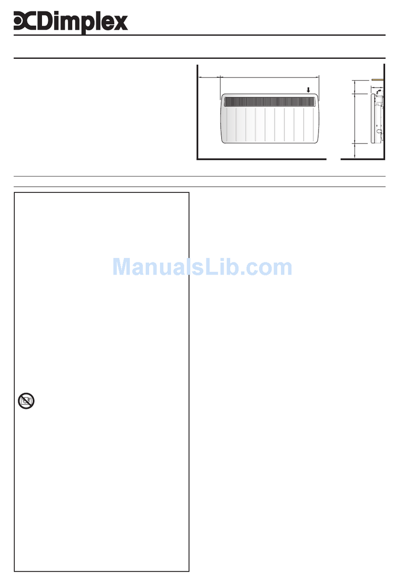
Dimplex HCT 300 Service manual

FD 8507 Page 1 of 2
Rohrheizung 3kW 351 210 / HCT 300
Tube immersion heater 3kW
Thermoplongeur 3kW
Montage- und Bedienungsanleitung
Mounting and Operating Instructions
Instructions de montage et de service 452115.66.13
Die Montage und Elekroinstallation muss
von einer zugelassenen Fachfirma erfolgen.
Die länderspezifischen Vorschriften (z.B.
DIN, VDE) und die technischen Anschluss-
bedingungen der Energieversorger sind zu
beachten.
Montage:
Die am Typenschild angegebenen Betriebs-
überdrücke dürfen nicht überschritten werden.
Die angegebene Durchflussmenge ist sicherzu-
stellen.
Die Rohrheizung ist im Heizungsvorlauf, nach
der Wärmepumpe, vorzusehen. Die Montage
muss senkrecht (Elektroteil oben) erfolgen und
ist ohne Absperrmöglichkeit mit einer Sicher-
heitseinrichtung, gemäß Anlagendruck, auszu-
rüsten.
Der Einsatz im Trinkwasserbereich ist nicht
zulässig.
Hinweise zur Installation: Verbindungsmuf-
fen fest anziehen und dabei am Nippel ge-
genhalten
Elektroinstallation:
Achtung: Anlage spannungsfrei schalten!
Die Elektroinstallation ist nach dem Schaltbild
Anlage 2 durchzuführen. In der elektrischen
Zuleitung ist ein allpoliger Trennschalter mit
mind 3 mm Kontaktöffnungsweite vorzusehen.
Als Trennschalter sind auch Sicherungsauto-
maten zulässig.
Nach der Montage ist das Anschlussgehäuse
zu öffnen und das Oberteil abzunehmen. Die
Dichtung und das Unterteil verbleiben am Ge-
rät.
Das vorbereite Kabel wird mittels beiliegender
Kabeleinführung zum Gehäuse abgedichtet. Die
Verschraubung ist fest anzuziehen und das
Kabel mittels Zugentlastung im Gehäuse zu
fixieren.
Nach der Verschaltung (Achtung: Schutzleiter
nicht vergessen!, Kontrolle der Verschaltung
nach Schaltplan) kann das Gehäuse durch
vorsichtiges Drehen ausgerichtet werden. Dabei
darf die Dichtung nicht beschädigt werden.
Vor dem Aufsetzen des Oberteiles ist ggf die
Dichtschnur in die Nut zu drücken. Das Gehäu-
se ist durch Festziehen der 4 Schrauben wieder
ordnungsgemäß abzudichten.
Mounting and electrical installation must be
performed by a competent specialist com-
pany. All relevant national provisions (e.g.
DIN, VDE) as well as technical connection
requirements of the utility companies must
be complied with.
Installation
The max. allowable working pressures indicated
on the rating plate must not be exceeded. The
specified flow rate must be ensured.
The tube immersion heater is to be installed in
the heating system flow circuit at the outlet of
the heat pump. The unit must be installed in
vertical position (electrical section at the top)
and a safety device without shut-off possibility
must be provided in accordance with the system
pressure.
The unit must not be installed in drinking
water applications.
Notes on installation: Firmly tighten con-
necting sleeves while counter-holding at the
nipple.
Electrical installation:
Caution: Disconnect the installation from the
power supply1
The electrical installation must be performed in
accordance with the wiring diagram in Appendix
2. The power supply must be provided with an
all-pole disconnecting switch with a contact
separation of at least 3 mm. Automatic circuit-
breakers may also be used as isolating de-
vices.
Following the installation, the cable connection
box needs to be opened and the upper part to
be removed. The gasket and the lower part
remain on the unit.
The pre-terminated cable is sealed against the
box by means of the supplied cable gland. The
screws are to be tightened firmly and the cable
to be secured to the box using the strain relief.
After the wiring has been completed (caution:
do not forget PE conductor, wiring to be
checked against the wiring diagram) the con-
nection box can be aligned by careful turning.
When so doing, take care not to damage the
gasket.
The packing cord may have to be pressed into
the groove prior to mounting the upper part. The
box is to be properly sealed again by tightening
the 4 screws.
Le montage et le branchement électrique
doivent être effectués par une entreprise
spécialisée agréée. Il faut respecter les
prescriptions du pays d’installation (par
exemple DIN, VDE) ainsi que les prescrip-
tions du distributeur d’énergie.
Montage
Les pressions de service indiquées sur la pla-
que signalétique ne doivent pas être dépas-
sées. Il faut assurer le débit d’eau indiqué.
Le thermoplongeur doit être intégré dans le
circuit aller du chauffage à la sortie de la
pompe à chaleur. Il faut monter le thermoplon-
geur en position verticale (la partie électrique en
haut) et prévoir un dispositif de sécurité non
verrouillable en fonction de la pression de
l’installation.
Il n’est pas admis d’utiliser le thermoplon-
geur pour l’eau potable.
Indications de montage : Serrer fermement
les manchons de raccordement tout en
maintenant le raccord fileté
Branchement électrique :
Attention : Mettre l’installation hors tension !
Pour effectuer le branchement électrique se
référer au schéma électrique en annexe 2. Il
faut prévoir, côté client, un dispositif de décon-
nexion avec déclenchement simultané de tous
les pôles avec au moins 3 mm d’écartement
d’ouverture. Les coupe-circuits automatiques
sont également admis comme dispositif de
déconnexion.
Après le montage du thermoplongeur, ouvrir le
boîtier de raccordement et enlever la partie
supérieure. Le joint et la partie inférieure restent
fixés sur l’appareil
Au moyen du passe-câble fourni, le câble
préparé est isolé du boîtier pour assurer l'étan-
chéité. Serrer à fond les vis et fixer le câble à
l’intérieur du boîtier au moyen d’une décharge
de traction.
Après avoir effectué le câblage (attention: ne
pas oublier le conducteur de protection et le
contrôle du câblage suivant le schéma électri-
que), il est possible d’orienter le boîtier en le
tournant prudemment. Veiller à ne pas endom-
mager le joint. Avant de replacer la partie supé-
rieure du boîtier, presser le joint d’étanchéité
dans la rainure. Resserrer à fond les 4 vis pour
rétablir l’étanchéité du boîtier
FD 8507 Page 2 of 2
Inbetriebnahme / Wartung:
Vor Inbetriebnahme ist zu prüfen, ob die Rohr-
heizung mit Wasser gefüllt ist. Hierbei ist die
Funktion und die Dichtigkeit der gesamten
Anlage zu prüfen und zu überwachen. Die
Funktion des Temperaturregler ist zu kontrollie-
ren. Die Funktionssicherheit des Sicherheits-
ventils ist in regelmäßigen Abständen zu über-
prüfen.
Achtung: am Gerät können heiße Oberflä-
chen auftreten
Technische Angaben:
Commissioning / Maintenance
Prior to commissioning it must be checked that
the tube immersion heater is immersed in water.
When so doing, the entire system is to be
checked and monitored for proper functioning
and a leakage test to be performed. The proper
operation of the temperature controller is to be
checked, and the functional reliability of the
safety valve, at regular intervals.
Caution: the surfaces of the unit may be hot.
Technical data:
Mise en service / Maintenance :
Avant la mise en service, il faut vérifier si le
thermoplongeur est immergé dans l’eau. A cette
occasion, contrôler et surveiller le bon fonction-
nement et l’étanchéité de toute l’installation.
Vérifier également la fonction du régulateur de
température. Il faut contrôler à intervalles régu-
lières la sécurité de fonctionnement de la sou-
pape de sécurité
Attention : L’appareil peut présenter des
surfaces chaudes
Caractéristiques techniques :
Spannung
Leistung
Wassermenge
Regelbereich
Wassertemperatur Eingang
Schutzart IP 44
Umgebungstemperatur 0-40°C
Temperaturbegrenzung 98°C
Anschlussgröße (flachdichtend) G 1“
Elektrische Absicherung 16 A
Leitungsquerschnitt nach Vorschrift und
örtlichen Gegebenheiten
Voltage
Rating
Water capacity
Adjustment range
Water temperature, inlet
Protection type
Ambient temperature
Thermal cut-out
Connection size (flat packing)
Fuse protection
Cross-sectional area of conductors accord-
ing to specifications and local conditions
Tension
Puissance
Quantité d‘eau
Plage de réglage
Température de l’eau à l‘entrée
Type de protection
Température ambiante
Limite de température
Raccord (joint plat)
Protection électrique
Section du conducteur en fonction des
prescriptions et des conditions locales
230V /50Hz
3000W(+5%/-10%)
500-2000l/h
20-75°C
2-60°C
IP 44
0-40°C
98°C
G 1“
16 A
Anlage 1: Appendix 1: Annexe 1 :
Abmaße und Einbau Dimensions and installation Dimensions et montage
oben
top
haut
unten
bottom
bas

Other Dimplex Heater manuals

Dimplex SAF6 Series User manual

Dimplex

Dimplex SAF6 Series User manual

Dimplex 2nc8 series User guide

Dimplex

Dimplex 2nc8 series User guide

Dimplex BK 1202 S User manual

Dimplex

Dimplex BK 1202 S User manual

Dimplex RPX100N User manual

Dimplex

Dimplex RPX100N User manual

Dimplex DHCER20FE User manual

Dimplex

Dimplex DHCER20FE User manual

Dimplex 3082S User manual

Dimplex

Dimplex 3082S User manual

Dimplex PLX050E User manual

Dimplex

Dimplex PLX050E User manual

Dimplex OFC1205 User manual

Dimplex

Dimplex OFC1205 User manual

Dimplex CEL50 User manual

Dimplex

Dimplex CEL50 User manual

Dimplex QUBEFAN Q2BT User manual

Dimplex

Dimplex QUBEFAN Q2BT User manual

Dimplex DIR Series User manual

Dimplex

Dimplex DIR Series User manual

Dimplex SLR 200WE User manual

Dimplex

Dimplex SLR 200WE User manual

Dimplex EVORAD2E User manual

Dimplex

Dimplex EVORAD2E User manual

Dimplex DDF250 Supplement

Dimplex

Dimplex DDF250 Supplement

Dimplex SRX 080M User manual

Dimplex

Dimplex SRX 080M User manual

Dimplex FFCH5000W Series User manual

Dimplex

Dimplex FFCH5000W Series User manual

Dimplex MFP Series User manual

Dimplex

Dimplex MFP Series User manual

Dimplex IRX50N User manual

Dimplex

Dimplex IRX50N User manual

Dimplex DXGLO2 User manual

Dimplex

Dimplex DXGLO2 User manual

Dimplex XLS User manual

Dimplex

Dimplex XLS User manual

Dimplex QUBEFAN Q2TSNH User manual

Dimplex

Dimplex QUBEFAN Q2TSNH User manual

Dimplex DTD2R05 User manual

Dimplex

Dimplex DTD2R05 User manual

Dimplex BEETHOVEN User manual

Dimplex

Dimplex BEETHOVEN User manual

Dimplex QRAD150 User manual

Dimplex

Dimplex QRAD150 User manual

Popular Heater manuals by other brands

Toyostove WC-105R Type F Operation and maintenance instructions

Toyostove

Toyostove WC-105R Type F Operation and maintenance instructions

Supplies4Heat BEAUFORT Slim Fitting instructions

Supplies4Heat

Supplies4Heat BEAUFORT Slim Fitting instructions

Kermi T. 10 Instruction and installation manual

Kermi

Kermi T. 10 Instruction and installation manual

Roca HOTELS A815502 manual

Roca

Roca HOTELS A815502 manual

Warmlite WL43009 Safety & instruction manual

Warmlite

Warmlite WL43009 Safety & instruction manual

Kermi UNN1008 Instruction and installation manual

Kermi

Kermi UNN1008 Instruction and installation manual

Flexit ProNordic installation instructions

Flexit

Flexit ProNordic installation instructions

Webasto Thermo Top V Operating and servicing manual

Webasto

Webasto Thermo Top V Operating and servicing manual

Haverland RC-4A Instruction and installation manual

Haverland

Haverland RC-4A Instruction and installation manual

Omega Altise ACUBOB Operation, maintenance and safety instructions

Omega Altise

Omega Altise ACUBOB Operation, maintenance and safety instructions

Marley U1000 Insallation & maintenance manual

Marley

Marley U1000 Insallation & maintenance manual

AGI GGH-8390 Installation, operation, and parts manual

AGI

AGI GGH-8390 Installation, operation, and parts manual

Rointe Impero electric OVAL 500 instruction & installation guide

Rointe

Rointe Impero electric OVAL 500 instruction & installation guide

Herschel COLORADO 2500R Installation & operating instructions

Herschel

Herschel COLORADO 2500R Installation & operating instructions

Honeywell HHF175 Series manual

Honeywell

Honeywell HHF175 Series manual

Stoveman Stoveman 16 Installation and operating manual

Stoveman

Stoveman Stoveman 16 Installation and operating manual

Sinbo SFH-3302 user manual

Sinbo

Sinbo SFH-3302 user manual

Ouellet OCC Series instructions

Ouellet

Ouellet OCC Series instructions

manuals.online logo
manuals.online logoBrands
  • About & Mission
  • Contact us
  • Privacy Policy
  • Terms and Conditions

Copyright 2025 Manuals.Online. All Rights Reserved.