manuals.online logo
Brands
  1. Home
  2. •
  3. Brands
  4. •
  5. Dimplex
  6. •
  7. Heater
  8. •
  9. Dimplex RPX075N User manual

Dimplex RPX075N User manual

Electronic Radiant Panel Heater
Models:
RPX075N / RPX100N / RPX150N / RPX200N
Dimensions and Specification
Model Loading Length
(A) Height Depth X Y Z Weight
(kW) (mm) (mm) (mm) (mm) (mm) (mm) (kg)
RPX075N 0.75 515 440 110 178 124.5 212.5 4.3
RPX100N 1.0 620 440 110 248 159.5 212.5 5.3
RPX150N 1.5 830 440 110 405 212.5 212.5 7.2
RPX200N 2.0 1040 440 110 535 252.5 252.5 9.0
THESE INSTRUCTIONS SHOULD BE READ CAREFULLY AND RETAINED FOR FUTURE REFERENCE
Installation and Operating Instructions
Wall Mounting / Installation
The heater should be positioned observing the minimum clearances
stated around the heater.
(see also ‘Electrical’ section)
The wall bracket supplied with the heater must be used
1. Remove wall mounting bracket from back of heater by de pressing
the two spring latches at the top of the heater (see Fig.1)
2. Fix wall bracket securely to wall via the three or four holes in the
bracket with the appropriate fixings for the wall type (see Fig.2)
3. Present heater to wall bracket and engage the two lower slots first.
Then line up and push in the top two slots until the spring latches
click in to place
General
The compact RPX range of radiant panel heaters are designed to
provide comfortable radiant heat in both domestic and commercial
applications.
Model A (Width) B (Bracket
Width) C
RPX075N 515 178 212.5
RPX100N 620 248 212.5
RPX150N 830 405 212.5
RPX200N 1040 535 252.5
IMPORTANT SAFETY ADVICE
•When using electrical appliances, basic precautions should always be
followed to reduce the risk of fire, electrical shock, and injury to
persons, including the following:
•WARNING THE SURFACES OF THIS HEATER CAN BE HOT
Momentary contact with any part of the heater should not cause injury.
However, aged or infirm persons or young children should not be left
unsupervised in the vicinity of the heater unless a suitable guard is
fitted
•IMPORTANT – If this heater is installed in a room containing a bath or
shower, it should be so installed that switches and other controls
cannot be touched by a person using a bath or shower – to comply
with this requirement see ‘Lock the Control Cover’ section on page 2.
•If you use this heater in conjunction with an external thermal control, a
programme controller, a timer or any other device which switches the
heat on automatically, observe all safety warnings AT ALL TIMES since
a fire risk exists when the heater is accidentally covered or displaced
•The installation of this product should be carried out by an electrician
or competent person and be in strict accordance with the current IEE
Wiring Regulations and relevant Building Regulations
•This heater must not be mounted within 150mm of curtains and other
combustible materials or 100mm from a shelf or overhang
•NEVER cover or obstruct in any way the heat outlet slots at the top of
the heater or the air inlet slots at the base of the heater
•DO NOT cover the heater – Do not place material or garments on the
heater or obstruct the air circulation around the heater
•Before connecting the heater check that the supply voltage is the same
as that stated on the heater
•The heater must be installed in accordance with these instructions
•The heater must be mounted using the wall bracket supplied. The
heater should only be operated in the upright position
•The heater should be positioned in accordance to the clearances
stated in these instructions
•DO NOT locate this heater immediately beneath a fixed socket outlet
Pilot Wire Connection
The BLACK control wire is designed to carry a signal from slot in or wall mounted Dimplex
programmers. If, however a programmer is not being used, the pilot wire should be
isolated in accordance with the current IEE Wiring Regulations.
Do NOT connect the BLACK pilot wire to earth
Any 240V insulated cable may be used to link pilot wires around the ring main. A low
signal current is used. Suitable connections would be either an additional single core wire
marked or colour coded appropriately or use a 4 core cable throughout the ring main.
Please refer to the relevant programmer installation and operating instructions for further
details on pilot wire connection
Electrical
The wires in the mains lead are coloured in accordance with the following code:
GREEN & YELLOW EARTH
BLUE NEUTRAL
BROWN LIVE
BLACK PILOT WIRE
(See also ‘Pilot Wire Connection’)
The heater is fitted with a length of flexible cable for connection to the fixed wiring of
the premises through a suitable connection box positioned adjacent to the heater.
The supply circuit to each heater must incorporate a double pole isolating switch having
a contact separation of at least 3mm
Fig.1
Fig.2
IP24 Issue 3 Octobe
r
2010
This appliance complies with European Safety Standard EN 60335-2-30, and European Standards EN 55014, EN 60555-2 and EN60555-3 for Electromagnetic
Compatibility. These standards cover the requirements of the EEC Directives 73/23 and 89/336.
Symbol Function Description
Frost Protection Heater will switch on to provide frost
protection if the room drops below
5ºC
Economy (set back) Heater will maintain a lower
temperature level for background
heating (comfort less 3.5ºC)
Comfort Heater will maintain the temperature
set on the thermostat dial
Off Heater will not function
Programme Heater will be controlled by a
programming device
Operation
Off
Note: If the programme function is selected but no programming device is being
used, the heater will function in comfort mode
The following Dimplex programmers are available:
Pilot Wire Wall Mounted Controller (2 Zone) – Part no. RX010006
MBS Wall Mounted Programmer (2 Zone) – Part no. RX010007
MBS Slot in Receiving Cassette – Part No. RX9913
MBS Slot in Programming Cassette (Single Zone) – Part no. RX9912
Pilot Wire Programming Cassette (Single Zone) – Part no. RX9911
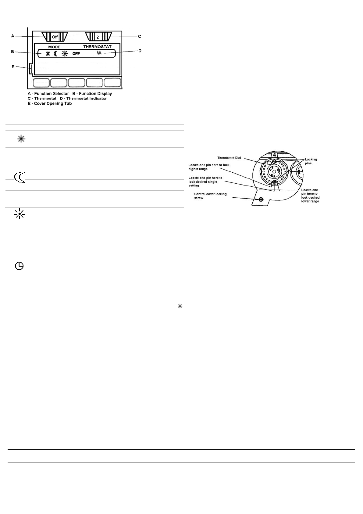
Function Display (B)
Neon indicators adjacent to the function selector will light to show the mode
selected
Setting the Comfort Temperature (C)
Use the thermostat dial (C) to select your desired room temperature. The
markings on the dial are in approximately 3.5ºC increments. The settings are
(Frost Protection) and numbers 1-10 (MAX). The quickest way to find your comfort
setting is to turn the thermostat dial to the maximum setting. When your ideal
comfort level is achieved, turn the thermostat dial down until the thermostat
switches off (the neon light will go out) Leave at this setting and the heater will
automatically maintain the desired temperature.
Advice on Using your Heater
•For greatest economy switch the heater to economy (setback) if you
leave the room for long periods of time or before going to bed.
•Do not set the comfort level too high. Even small reductions on the
thermostat setting can save a lot of energy.
•If you go away for a long period of time select the frost protection setting
on the function dial or reduce the thermostat setting to a lower level.
Locking the Thermostat Setting (C)
If necessary you can lock the thermostat dial to a single setting or range.
To lock the settings, use a small pair of narrow nosed pliers to pull out the
locking pins at the rear of the thermostat dial.
The following settings can be obtained: (see Fig.4)
•Single setting – Set thermostat dial to desired setting (eg no.6). Locate
one pin directly opposite the setting required
•Minimum setting – Set thermostat dial to desired setting (e.g. no.6).
Locate one pin opposite the setting required and one hole to the left.
(The thermostat will now be adjustable from 6-9 only)
•Maximum setting – Set thermostat dial to desired setting (eg
no.6).Locate one pin opposite the setting required and one hole to the
right. (The thermostat dial will now be adjustable from 1-6 only)
•Minimum - maximum setting – (e.g. no.2-4) Locate both pins and
space apart until desired range is found
To Lock the Control Cover (F)
A screw is provided to permanently lock the cover in position. It is located on
the back of the control box, under the thermostat dial. Remove this and
screw through the notch below the lifting tab into the plastic housing. (see
also Fig.4 above)
Safety
A thermal cut-out will switch off the heater if, for any reason, it overheats.
Should the cut-out operate, switch off the mains supply and allow the heater
to cool. Once the heater has cooled sufficiently remove the obstruction and
switch on the mains supply.
Cleaning
Before cleaning your heater, switch off the heater and allow it to cool.
Disconnect the electricity supply to the appliance. The outside can be
cleaned by wiping it over with a soft damp cloth and then dried. Do not use
abrasive cleaning powders or furniture polish, as this can damage the
surface finish. To release the heater from the wall bracket for cleaning or
redecoration, depress latch on both brackets and hinge forward.
After Sales Service
Your product is guaranteed for one year from the date of purchase.
Within this period, we undertake to repair or exchange this product free of
charge (excluding lamps & subject to availability) provided it has been
installed and operated in accordance with these instructions.
Your rights under this guarantee are additional to your statutory rights, which
in turn are not affected by this guarantee.
Should you require after sales service you should contact our customer
services help desk on 0870 727 0101. It would assist us if you can quote the
model number, series, date of purchase, and nature of the fault at the time of
your call. The customer services help desk will also be able to advise you
should you need to purchase any spares.
Please do not return a faulty product to us in the first instance as this may
result in loss or damage and delay in providing you with a satisfactory
service.
Please retain your receipt as proof of purchase.
Glen Dimplex UK Ltd
Millbrook House
Grange Drive
Hedge End
Southampton
SO30 2DF
UK Customer Help Line (8am-6pm Mon-Fri; 8:30am-1pm Sat.)
Customer Services: Tel: (0870) 727 0101
Fax: (0870) 727 0102
E-mail:[email protected]
Web-site: www.dimplex.co.uk
Republic of Ireland Tel: 01 842 4833
Mode Selection Dial (A)
Use this rotary dial to select the function you require
Thermostat Light (D)
The neon indicator below the thermostat will light when the heater is
operating.
Background (set back)
The economy setting is preset at -3.5ºC this is the amount the room
temperature will be allowed to drop when you switch the function selector
from comfort to economy.
Reverting to comfort mode will automatically cause the temperature to rise to
the setting on the thermostat dial.
Fig.4

This manual suits for next models

3

Other Dimplex Heater manuals

Dimplex 402BT User manual

Dimplex

Dimplex 402BT User manual

Dimplex xln User manual

Dimplex

Dimplex xln User manual

Dimplex CXLS12N User manual

Dimplex

Dimplex CXLS12N User manual

Dimplex FrostWatcher FW600 User manual

Dimplex

Dimplex FrostWatcher FW600 User manual

Dimplex DGP1000-B User manual

Dimplex

Dimplex DGP1000-B User manual

Dimplex SLR 200WE User manual

Dimplex

Dimplex SLR 200WE User manual

Dimplex HL 185 T User manual

Dimplex

Dimplex HL 185 T User manual

Dimplex MH NO Series User manual

Dimplex

Dimplex MH NO Series User manual

Dimplex LPC Series User manual

Dimplex

Dimplex LPC Series User manual

Dimplex FX 20V User manual

Dimplex

Dimplex FX 20V User manual

Dimplex C70 User manual

Dimplex

Dimplex C70 User manual

Dimplex EWA-C 3kW Series User manual

Dimplex

Dimplex EWA-C 3kW Series User manual

Dimplex Winslow 36 User manual

Dimplex

Dimplex Winslow 36 User manual

Dimplex DX 410 User manual

Dimplex

Dimplex DX 410 User manual

Dimplex DHCH20E User manual

Dimplex

Dimplex DHCH20E User manual

Dimplex FX 20VL User manual

Dimplex

Dimplex FX 20VL User manual

Dimplex LPC Series User manual

Dimplex

Dimplex LPC Series User manual

Dimplex CTHK 630 User manual

Dimplex

Dimplex CTHK 630 User manual

Dimplex FSR 15...35 GW Quick guide

Dimplex

Dimplex FSR 15...35 GW Quick guide

Dimplex LEE Series User manual

Dimplex

Dimplex LEE Series User manual

Dimplex DXC20 User manual

Dimplex

Dimplex DXC20 User manual

Dimplex EWA-C Series User manual

Dimplex

Dimplex EWA-C Series User manual

Dimplex FX 20E IPX4 User manual

Dimplex

Dimplex FX 20E IPX4 User manual

Dimplex QXD1500 User manual

Dimplex

Dimplex QXD1500 User manual

Popular Heater manuals by other brands

Master FACTORY User and Maintenance Book

Master

Master FACTORY User and Maintenance Book

Stanley ST-02-230-E manual

Stanley

Stanley ST-02-230-E manual

Tulikivi AHTI Instructions for use

Tulikivi

Tulikivi AHTI Instructions for use

Holmes HLH4422M owner's guide

Holmes

Holmes HLH4422M owner's guide

Hyundai CON 300 instruction manual

Hyundai

Hyundai CON 300 instruction manual

Black & Decker HX230 Original instructions

Black & Decker

Black & Decker HX230 Original instructions

Trotec IDX 30 D Original instruction

Trotec

Trotec IDX 30 D Original instruction

Stealth SWP 9010 Operator's manual

Stealth

Stealth SWP 9010 Operator's manual

PCB Piezotronics T333B30 Installation and operating manual

PCB Piezotronics

PCB Piezotronics T333B30 Installation and operating manual

Dyna-Glo HeatAround360 User's manual and operating instructions

Dyna-Glo

Dyna-Glo HeatAround360 User's manual and operating instructions

dreo Atom One user manual

dreo

dreo Atom One user manual

Talhu Oy termo 55 user manual

Talhu Oy

Talhu Oy termo 55 user manual

Teesa TSA8038 owner's manual

Teesa

Teesa TSA8038 owner's manual

Desa 000-12 owner's manual

Desa

Desa 000-12 owner's manual

WILMS Mini VAL owner's manual

WILMS

WILMS Mini VAL owner's manual

Olimpia splendid Caldo Pop Instructions for installation, use and maintenance

Olimpia splendid

Olimpia splendid Caldo Pop Instructions for installation, use and maintenance

KLARBACH HL31537we instruction manual

KLARBACH

KLARBACH HL31537we instruction manual

cecotec READY WARM FORCE ROTATE 9890 instruction manual

cecotec

cecotec READY WARM FORCE ROTATE 9890 instruction manual

manuals.online logo
manuals.online logoBrands
  • About & Mission
  • Contact us
  • Privacy Policy
  • Terms and Conditions

Copyright 2025 Manuals.Online. All Rights Reserved.