Dino lift DINO 260XTD Technical specifications

MAINTENANCE
INSTRUCTIONS
DINO 260XTD
Dealer:Manufacturer:
Dinolift Oy
Raikkolantie 145
FI-32210 LOIMAA
Tel. +358 20 1772 400
www.dinolift.com


3
ORIGINAL INSTRUCTIONS
Valid from serial number
260XTD 26419 -

4
Maintenance instructions •DINO 260XTD
CONTENTS
1. TO THE MAINTENANCE PERSONNEL..................................................................... 6
1.1. GENERAL WARRANTY TERMS......................................................................... 7
1.2. SAFETY AND THE ENVIRONMENT................................................................... 8
1.2.1. General safety instructions for maintenance .................................................................8
1.2.2. Filling quantities of chemical substances.......................................................................9
1.2.3. Materials and recyclability..............................................................................................9
1.3. SAFETY-RELATED NOTIFICATIONS............................................................... 10
1.4. SAFETY DEVICES............................................................................................ 11
2. MAINTENANCE SCHEDULE.................................................................................... 15
2.1. SCHEDULE FOR INSPECTIONS REQUIRED BY THE AUTHORITIES .......... 17
2.2. LUBRICATION PLAN ........................................................................................ 18
3. ROUTINE MAINTENANCE DURING OPERATION .................................................. 19
3.1. INSTRUCTIONS FOR DAILY MAINTENANCE AND INSPECTIONS .............. 20
3.1.1. Check the condition of chassis, the boom and the work platform................................ 20
3.1.2. Check the tyres and tyre pressure...............................................................................20
3.1.3. Check the lights ...........................................................................................................20
3.1.4. Check the hydraulic oil level ........................................................................................20
3.1.5. Check the hydraulic hoses, pipes and connectors ......................................................20
3.1.6. Check the operation of the safety limit switches..........................................................21
3.1.7. Check the operating controls.......................................................................................21
3.1.8. Check the operation of the emergency descent, the emergency stop and the sound
signal 21
3.1.9. Decals, stickers and signs ...........................................................................................21
3.1.10. Instruction manuals......................................................................................................21
4. PERIODIC SERVICE.................................................................................................22
4.1. INSTRUCTIONS FOR MONTHLY SERVICE AND INSPECTION .................... 22
4.1.1. Lubricate the greasing points ......................................................................................22
4.1.2. Check and adjust the play between the slide pads and the slide surface ...................22
4.1.3. Check the adjustment of the tow hitch and the overrun brake..................................... 23
4.1.4. Check the driving device..............................................................................................24
4.1.5. Check the condition and attachment of the battery and the wiring..............................24
4.1.6. Check the operation and condition of the platform's levelling system .........................24
4.2. INSTRUCTIONS FOR INSPECTIONS EVERY 6 MONTHS............................. 25
4.2.1. Check and lubricate the turning device bearings and the gear ring............................. 25
4.2.2. Lubricate the telescope cylinder bearings ...................................................................25
4.2.3. Lubricate the Flyer-chain .............................................................................................25
4.2.4. Check the attachment of the wheels and the tyre pressures.......................................25
4.2.5. Lubricate the tow hitch and the overrun.......................................................................26
4.2.6. Check the condition of the brakes ...............................................................................26
4.2.7. Checking the adjustment of the overload protection device ........................................27
4.2.8. Check the operation of the load regulation valves.......................................................27

5
4.3. INSTRUCTIONS FOR ANNUAL MAINTENANCE OF THE LIFT...................... 29
4.3.1. Inspect thoroughly the support outriggers and the outrigger cylinder joints ................ 30
4.3.2. Check the frame structures, the boom system, the work platform and the platform carrier
30
4.3.3. Check thoroughly the tow hitch and the overrun ......................................................... 31
4.3.4. Inspect thoroughly the hydraulic hoses, pipes and connections..................................32
4.3.5. Inspect the axle and the suspension ........................................................................... 32
4.3.6. Check thoroughly the condition of the brakes..............................................................32
4.3.7. Check electro-hydraulic rotary adaptor........................................................................32
4.3.8. Inspect thoroughly the turning device..........................................................................33
4.3.9. Inspect thoroughly the Flyer-chains.............................................................................34
4.3.10. Inspect the cylinders, and lubricate the joint bearings.................................................35
4.3.11. Check the battery, the electrical appliances and the wiring .........................................35
4.3.12. Measure hydraulic pressures.......................................................................................36
4.3.13. Inspecting the condition and functionality of the operating controls ............................ 36
4.3.14. Decals, stickers and signs ...........................................................................................37
4.3.15. Instruction manuals......................................................................................................37
4.3.16. Check the attachment and condition of the safety devices..........................................37
4.3.17. Checking the operation of the safety limit switches.....................................................37
4.3.18. Checking the operation of the overload limit switches RK4 and RK5..........................38
4.3.19. Test loading..................................................................................................................40
4.3.20. Check the lights ...........................................................................................................41
4.3.21. Inspect thoroughly the driving device ..........................................................................41
4.3.22. Lubricate the slide and threads of the jockey wheel....................................................41
4.3.23. Changethehydraulicoilandthelter .........................................................................41
4.3.24. Inspect the anti-corrosion treatment ............................................................................41
4.4. ADJUSTING THE OVERLOAD LIMIT SWITCHES........................................... 42
4.5. SPECIAL INSPECTION .................................................................................... 42
5. INSTRUCTIONS FOR FAULT-FINDING ................................................................... 43
5.1. PROBLEMS RELATED TO POWER SUPPLY AND START-UP ....................... 43
5.2. OPERATIONAL PROBLEMS RELATED TO MOVEMENTS............................. 45
5.3. DRIFTING OF BOOM OR OUTRIGGERS........................................................ 47
5.4. PROBLEMS RELATED TO TOWING................................................................ 49
6. HYDRAULIC SYSTEM .............................................................................................. 51
6.1. HYDRAULIC COMPONENTS 26209 ja 26229 ->............................................. 51
5.5. HYDRAULIC DIAGRAMS ................................................................................. 51
7. ELECTRIC SYSTEM ................................................................................................. 53
7.1. ELECTRIC COMPONENTS.............................................................................. 53
7.2. ELECTRIC DIAGRAM....................................................................................... 59

6
Maintenance instructions •DINO 260XTD
1. TO THE MAINTENANCE PERSONNEL
Thismaintenanceinstructionmanualisintendedtogivethequaliedserviceperson,who
is familiar with the basic structure of the lift, the required instructions for maintenance,
adjustments and repairs of the lift.
These maintenance instructions are an addition to the operating instructions. It is essential,
that the person, responsible for the maintenance, has familiarised himself
with the operating and safety instructions of the lift before
starting the service operations.
DANGER
WARNING
CAUTION
NOTICE
Perform all the service and repair operations in accordance with the local regulations for
occupational safety.
Exercise particular caution while performing service- and maintenance operations. A faulty
machine may cause severe, unforeseen risks.
If you are not sure which parts, tools or measures are necessary, consult your dealer or the
manufacturer's service organisation.
Dinolift Oy is constantly developing its products. For this reason, the contents of this manual
might not always be in full compliance with the most recent version of the product. Dinolift Oy
reserves the right to modify the product without prior notice. Dinolift Oy assumes no liability
for any problems caused by changed or missing data or mistakes in this manual.
Please consult your dealer or the manufacturer for more information and detailed
instructions.
DANGER
WARNING
CAUTION
NOTICE
The operator must receive instructions and consent from the manufacturer for
all such specic work methods or conditions, as well as for service, repair or
modication operations, that the manufacturer has not explicitly dened in the unit's
operation and maintenance instructions.

7
1.1. GENERAL WARRANTY TERMS
Dinolift Oy warrants newly delivered DINO aerial work platforms to be free from defects in
materials, constructional parts, components and workmanship, with terms and limitations set
out in the warranty terms. Full warranty terms are provided by the distributor.
The warranty period starts from the date of delivery from factory. Warranty cases related to
engines and generators or other accessories manufactured by external suppliers are to be
handled by and with the local authorized distributor of each respective manufacturer.
The warranty covers only the cost of constructional parts and components used in the
equipment. The warranty does not cover:
• damage or loss caused by transportation.
• damage or loss caused by misconduct, misapplication or accident damage, failure or
losscausedbynegligenceofinstructions,manufacturerspeciedserviceprogram,
maintenance or storage.
• normal wear of the equipment and damage resulting therefrom, nor wearing parts and
materials,suchasrubbertyres,seals,hoses,ttings,batteries,lters,etc.
• damage, failure or loss caused by maintenance or repair work performed by unauthorised
service personnel.
• damage, failure or loss caused by the purchaser’s acts or omissions causing alterations
ormodicationstothestructure,congurationorqualityoftheproduct.
• anyindirectdamageorlosssuchaslossofprotanddowntimecosts,etc.
• any claims by a third party.
• any damage caused to other property.
Warranty claims and damaged parts shall be processed according to Dinolift instructions of
warranty procedure. Contact the distributor for further instructions. No claim will be accepted
ifDinoliftnoticationandwarrantyproceduresarenotfollowedornon-originalpartsorparts
not approved by the Supplier have been used.
For more information on warranty procedures, contact the distributor or
Dinolift Oy
After Sales Services
Raikkolantie 145
FI-32210 Loimaa
Finland

8
Maintenance instructions •DINO 260XTD
1.2. SAFETY AND THE ENVIRONMENT
1.2.1. General safety instructions for maintenance
Exercise particular caution always when carrying out service- and maintenance operations.
A faulty lift, or a lift from which covers, safety devices or other parts have been removed,
may operate in an unexpected way.
If you must disable any of the safety devices for maintenance, make sure to resume its
operation after the maintenance, and check that it works correctly.
Beware of sudden and unexpected movements.
Support the platform, the boom system, the articulated arms and the support outriggers in
a position where the load does not rest on the structure under repair or cause any other
danger (e.g. in transport position or use of supporting structures)
When removing hydraulic cylinders, also note that
• the cylinders may be oily and slippery
• the cylinders are heavy. Use a lift and suitable lifting gear for lifting
Do not spill oil on the ground.
Dispose of used oils and oily waste appropriately. Observe the local regulations and the
regionalorsite-specicrecyclinginstructions.
Remember when handling batteries:
Electrolytic liquid is highly corrosive – always wear protective clothing and eye guards.
Thebatteriesgeneratehydrogengasduringcharging–nakedameprohibited,dangerof
explosion
Use genuine spare parts for maintenance. This way, you will ensure correct operation and
structural safety of the lift even after the maintenance.

9
1.2.2. Filling quantities of chemical substances
Liquid type Volume
Hydraulic oil
Fuchs Hydraway Bio SE 22
Fuchs Hydraway Bio SE 32-68
Mobil EAL 32
30-35 l
Hydraulic oil (winter option) Neste Hydrauli 28 Arctic 30-35 l
Lubricant Mobilux EP2 NLGI 2
Mobil Grease XHP 222
Chain lubricant Würth HHS Grease
Engine oil SAE 10W-30 1.1 l
Consulttheseparateenginemanualformoreinformationandspecicrecommendationsfor
engine oil.
Thehydraulicoiltype,usedinthelift,ismarkedonthelabel,afxedtothesideofthe
reservoir.
1.2.3. Materials and recyclability
Tyres
Type Radial M+S Size 225/75R17,5
The tyres meet the requirements of the REACH regulation.
The tyres can be recycled. A recycling fee has been paid for the tyres, so the used tyres may be left
for recycling if they are replaced.
Note the national and local regulations and policies.
Other materials
Metals
Steel, aluminium, cast iron
RecyclableHydraulic pipes and components
Power pack, axles
Plastics
Covers,mudaps(ABS,PE) Recyclable
Plastic parts are marked with material
ID.
Tyres
Battery Lead battery Recyclable
Electric components Wires, components Partly recyclable
Hydraulic hoses Not recyclable Hazardous waste.
Oils and lubricants Usedoils,oilyltersetc. Not recyclable Hazardous waste.

10
Maintenance instructions •DINO 260XTD
1.3. SAFETY-RELATED NOTIFICATIONS
The following safety alert symbols and safety signal words are used in this manual.
Observe all the safety instructions that follow these symbols, in order to avoid dangerous
situations and personal injuries.
This is a general safety alert symbol and it is used to alert you about a potential
hazard. Observe the additional instructions given in form of text or symbols that
follow this symbol.
DANGER
WARNING
CAUTION
NOTICE
Red DANGER-message warns for an imminent or potential hazardous situation which, if not
avoided, may result in death or serious injury.
DANGER
WARNING
CAUTION
NOTICE
Orange WARNING -message is used in connection with potential risk factors, which if not
avoided, under certain conditions, may result in death or serious injury.
DANGER
WARNING
CAUTION
NOTICE
Yellow CAUTION -message is used to warn about a hazardous situation which, if not
avoided, could result in minor or moderate injury.
DANGER
WARNING
CAUTION
NOTICE
Bluenotice-messageisusedtodrawyourattentiontospecialnoticationsorinstructions
that are related to the operation or maintenance. Such messages include, for example,
instructions that are related to reliability of the machine or aim to avoid material losses.
11
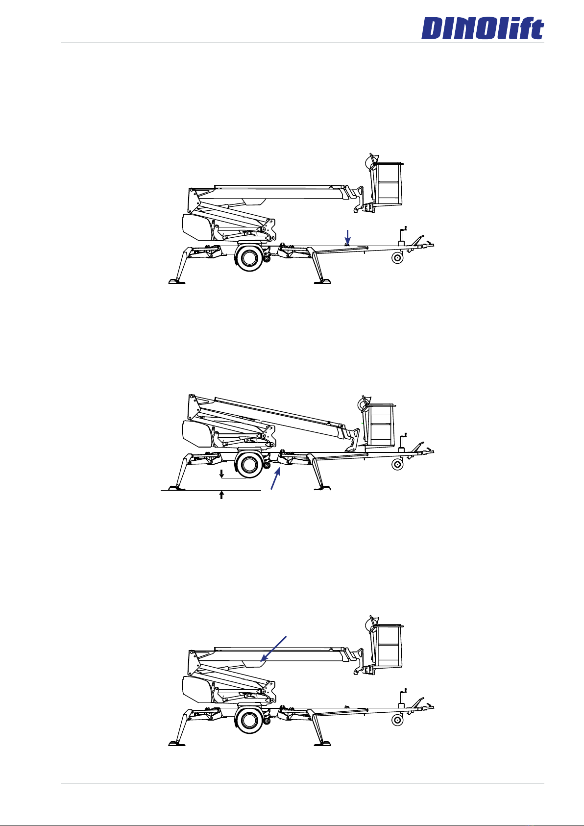
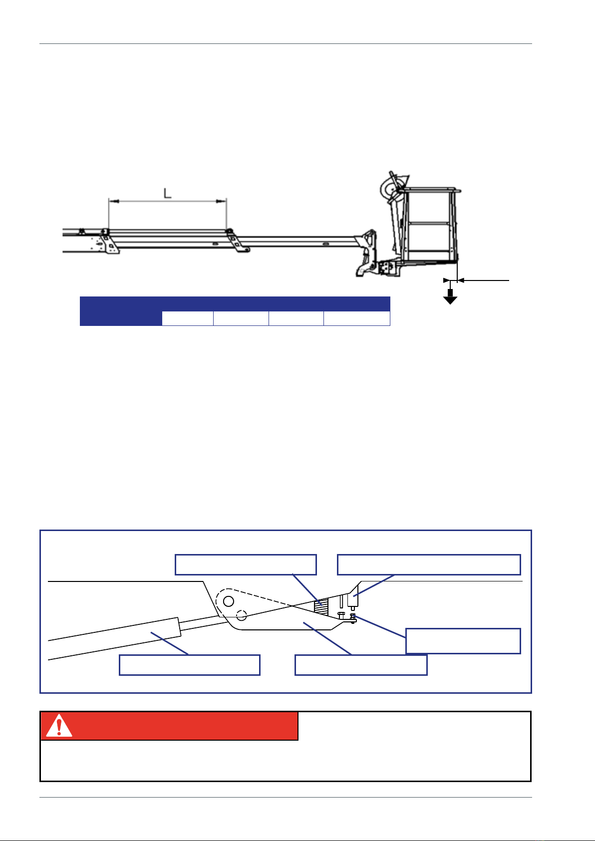
1.4. SAFETY DEVICES
1. Supervision of transport position of the boom
The safety limit switch RK3 prevents the operation of the outriggers and the driving device
when the boom is not resting on the transport support. The switch is located on the tow-bar
at the transport support.
RK3
2. Supervision of supporting
The lift’s all support outriggers must be in the support position before the boom is lifted.
Make sure that the wheels are off the ground.
The safety limit switches RK11, RK12, RK13 and RK14 are located on the support
outriggers.
RK11, RK12, RK13, RK14
3. Overload control of the boom
The outreach limit switch RK4 and overload limit switch RK5 prevent the lift from being
overloaded by limiting the outreach of the lift to the side.
The limit switches are located under the cover at the top end of the lifting cylinder. During
operation, the cover must be intact and in place.
RK4, RK5
12
Maintenance instructions •DINO 260XTD
The green light in the control centre on the platform is lit, when the platform is within the
allowed operating range.
The reach limit switch RK4 will stop the movements, which impair the stability of the lift
(extending the telescope and lowering the boom), at a predetermined position.
Adjusted values of the limits:
100 mm
w
W RK4 - L RK5 - L
260XTD 80 kg 2050 mm 2350 mm +0 / -50 mm
The red warning light for overloading will illuminate as soon as the RK4 has stopped the
movement. While at the outreach limit, the red warning light and the green signal light will
ashinturns.Inthissituation,theliftcanbeoperatedinthedirection,inwhichitremains
inside the permitted outreach area.
The overload limit switch RK5 backs up, if the RK4, for some reason, does not work.
Once the RK5 is activated, the red warning light for overloading in both control centres will
be continually illuminated, and a warning buzzer will sound on the platform.
The operation of the overload limit switches is based on monitoring of the boom's lifting
torque.
PRESSURE SPRING
LIFTING CYLINDER ARTICULATED ARM
LIMIT SWITCHES RK4 and RK5
ADJUSTMENT
SCREWS
DANGER
WARNING
CAUTION
NOTICE
The limit switches must never be readjusted, nor the operation of the mechanism be
impeded. Risk of turning over the lift!

13
5. Supervision of the telescope chain
The extension chains for the telescope are doubled.
If the load-bearing chain slackens or breaks, the
doubling chain prevents the movements of the
telescope, and the safety switch RK7/RK15 breaks
the emergency stop circuit.
RK15
RK7
~
3
mm
~32
mm
~
40
mm
AA
A - A
A
B
A
B
C
C
LIMIT SWITCH RK7/RK15
EXTENSION CHAIN
DOUBLING CHAIN
RETRACTION CHAIN
6. Preventing the inclination of the platform
The platform is levelled hydraulically by means of a so-called slave cylinder system, where
the master cylinder controls the slave cylinder that inclines the work platform.
The platform keeps its level position only if the
valves in the system are tight.
The levelling system comprises the following
parts:
• Master cylinder
• Slave cylinder
• Load regulation valve
• Double load regulation valve

14
Maintenance instructions •DINO 260XTD
7. Safety devices for hose rupture
All the load-bearing cylinders are equipped with valves for rupture or leak in the hydraulic
system, which prevent the load from falling.
Outrigger cylinders Lock valves Prevent the inching of the
outriggers in either direction.
Lifting cylinder of the boom Load regulation valve Prevents the load from falling
Lifting cylinder of the
articulated arms Load regulation valve Prevents the load from falling
Telescope cylinder Load regulation valve Prevents the inching of the
telescope in either direction.
Levelling system Load regulation valves Prevents the inclination of the
platform
7. Emergency stop buttons
Depressing the emergency stop button, stops all the movements immediately and turns off
the power unit. The button can be found at each control station. Once the button has been
depressed, only the emergency descent functions remain operational.
The emergency stop button locks in the lower position, and it must be released before
starting the power unit.
DANGER
WARNING
CAUTION
NOTICE
If the unit does not start, make sure that the emergency descent button is not in the lower
position at any of the control stations.
Theemergencystopbuttonintheplatformcontrolcentreisttedwithasignallight,which
remains illuminated while the lift is in the normal operating mode. The light will go out, if the
emergency stop function is activated by any of the emergency stop switches or by the safety
device.
15
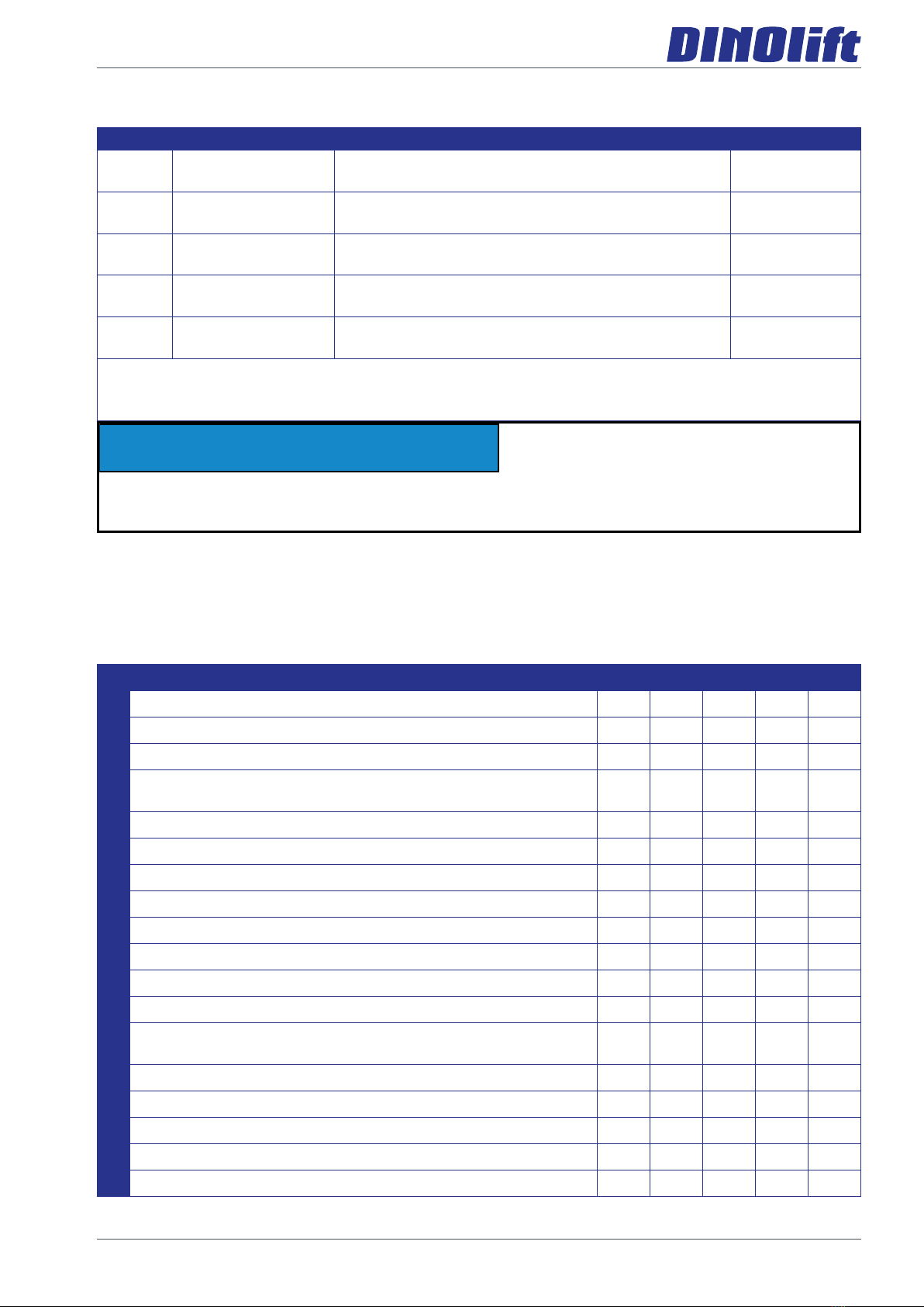
2. MAINTENANCE SCHEDULE
Maintenance measures A B C D E
1Frame structures, boom system and platform T T T P
2Bearings of the overload protection device V T/V T/V
3Joints of the outriggers and the outrigger cylinders V T/V P/V
4Joints of the outriggers' foot plates and the moving parts of
the outrigger limits V T/V P/V
5Bearings of the boom and the articulated arms V T/V T/V
6Bearings of the levelling system of the platform V T/V T/V
7Articulation bearings of the levelling cylinders V T/V T/V
8Articulation bearings of the lifting cylinders V T/V T/V
9Sliding surfaces and rollers of the telescope T/V T/V T/V
10 Bearing of telescope cylinder T/V T/V
11 Condition of cylinders P
12 Flyer-chain V P/V
13 Checking and adjusting the play between slide pads and
surfaces TTT
14 Turning device V P/V
15 Electro-hydraulic rotary adaptor T
16 Tyres and tyre pressures T T P P
17 Tow hitch/overrun T V P/V
18 Jockey wheel slide and threads P/V
DANGER
WARNING
CAUTION
NOTICE
In addition to the daily maintenance routines according to the maintenance schedule, every
operatorisobligedtoperformasite-specicworksiteinspection.
T = Check (general/visual checking of condition).
P = Thorough Inspection. To be performed follwing the separate procedure described in the
maintenance instructions.
V = Grease
S = Carry out replacements, repairs or other maintenance tasks described in the instructions
Service Service interval Service person Instructed
A Daily Operator operating
instructions
Bevery month/100
hours* Competent person who is familiar with the lift maintenance
instructions
Cevery 6 months/400
hours* Competent person who is familiar with the lift maintenance
instructions
Devery 12
months/800 hours*
Technical specialist, who is well familiar with the
structure and operation of the lift
maintenance
instructions
E When necessary Technical specialist, who is well familiar with the
structure and operation of the lift
maintenance
instructions
* Service interval in months or operating hours, depending on whichever
comesrst.
16
Maintenance instructions •DINO 260XTD
Alwayslubricatetheliftandapplyaprotectivegreaselmimmediatelyafterthewashing.
The lift must always be subjected to a special inspection after an exceptional event. Special
inspection is required if the lift has been damaged in a manner,which may affect its load-
bearing capacity or safe operation. Consult the maintenance manual for more detailed
instructions.
DANGER
WARNING
CAUTION
NOTICE
If the lift is equipped with a petrol-driven or a diesel power pack, then in addition to the
normal maintenance routines must also be carried out the service measures in accordance
with the power pack's manual.
DANGER
WARNING
CAUTION
NOTICE
Under demanding conditions where moist, corrosive substances or corrosive climate may
speed up the deterioration of the structures and induce malfunctions, the maintenance
intervalsmustbeshortened,ortheinuenceofcorrosionandmalfunctionsmustbereduced
by using appropriate protective means.
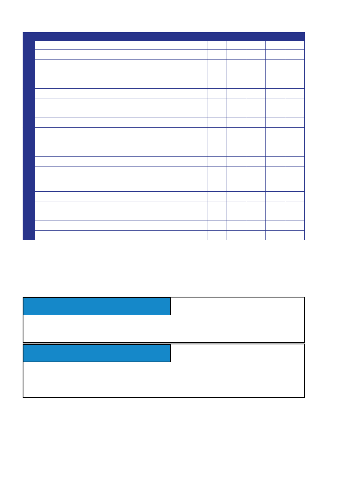
19 Condition of brakes T T
20 Axle and suspension P
21 Driving device T V P
22 Lights T T T P
23 Hydraulic oils T T T S
24 Hydraulic hoses, pipe and conections T T T P
25 Condition and attachment of battery and wiring T T P
26 Hydraulic pressure P
27 Condition and attachment of safety devices T
28 Operation of safety devices (limit switches) T T T P
29 Operation of overload limit switches T P S
30 Operation of load regulation valves T T
31 Operation and condition of platform's levelling system T T T
32 Operation and condition of controls on platform T P
33 Operation of emergency descent, emergency stop and
sound signal TTTT
34 Stickers, plates and instructions T T T T
35 Test loading P
36 Anti-corrosion treatment T S
37 Adjusting the movement speeds S
38 Special inspection S
Maintenance measures A B C D E

17
2.1. SCHEDULE FOR INSPECTIONS REQUIRED BY THE AUTHORITIES
The inspections must be performed in accordance with local and national regulations,
in accordance with the legislation and standards.
The lift must be subjected to a start-up inspectionbeforeitisusedforthersttimeand
beforestartingitupthersttimeafteramajorrepairormodicationwork.
The lift must be subjected to a thorough periodic inspection with related test drive at
intervals of year.
Theinspectionmustbecarriedoutwithintwelve(12)monthsoftherstinspectionor
previous regular inspection.
In connection with the periodic inspection the lift must be subjected to a non-destructive
inspection/inspection disassembled in general at intervals of ten (10) years from the start-
up date.
In addition, the lift much be inspected to the extent applicable after any exceptional situation
The inspections of the lift must be carried out at regular intervals as long as it is in use.
If the lift is used under extreme conditions, intervals between the inspections shall be
reduced.
The overall operating condition of the lift as well as the condition of the safety-related control
devices shall be established in the regular inspections. Particular attention shall be paid to
changes, which affect the operational safety.
In connection with the regular inspection shall be established to what extent the lessons and
practical experience gained since the previous inspection could be utilized to improve the
safety even more.
For the inspection must be assigned an expert inspection body with documented
evidence of competence or an expert with documented evidence of competence.
A protocol must be drawn up of the executed inspections. The protocols of the start-up
andperiodicinspectionsmustbekeptwiththeliftoritsimmediateproximityforatleastve
years.
DANGER
WARNING
CAUTION
NOTICE
Check the regulations for the inspections and the competence of the inspector with
the local authorities.

18
Maintenance instructions •DINO 260XTD
6
9
7
11
7
8
1
5
5
3 2 12
3
4
10
13
2.2. LUBRICATION PLAN
14

19
3. ROUTINE MAINTENANCE DURING OPERATION
The maintenance operations, that are the responsibility of the operator, are described in this
chapter.
The more demanding maintenance operations that require special skills, special tools or
specicmeasurementsandadjustmentvaluesareinstructedintheseparateMaintenance
Instructions. In such maintenance and repair cases, the operator shall contact an authorized
service provider, the distributor or the manufacturer.
Make sure that all the service and maintenance procedures of the lift are performed in time
and according to the given instructions.
DANGER
WARNING
CAUTION
NOTICE
Any such faults, observed during operation or periodic service, which affect the operational
safety of the unit, must be repaired before the lift is used next time.
Keep the lift clean. Clean the lift especially carefully before services and inspections.
Impurities may cause serious problems, for example, in the hydraulic system.
Use original spare parts and consumables. Consult the spare parts list for more detailed
information about the parts.
The rst service after 20 hours of operation
• changethepressureandreturnlterelements
• adjust the brakes according to the instructions (see point “Wheel brakes and bearings”)
• check the wheel bolts for tightness after about 100 km of driving
If the lift is operated under demanding conditions (in exceptionally humid
or dusty environment, corrosive climate, etc.) the intervals between the
oil changes and the other inspections shall be shortened to meet the
prevailing conditions in order to maintain the operational safety and
reliability of the lift.
The timely performance of the periodic servicing and the inspections
is absolutely mandatory, because neglecting them may impair the
operational safety of the lift.
The guarantee will not remain valid, if the servicing and the periodic
inspections are not performed.
20
Maintenance instructions •DINO 260XTD
3.1. INSTRUCTIONS FOR DAILY MAINTENANCE AND INSPECTIONS
3.1.1. Check the condition of chassis, the boom and the work platform
Check visually the condition of the access routes, the work platform, the platform gate and
the handrails.
Check visually the condition of the boom and the frame structures.
3.1.2. Check the tyres and tyre pressure
Checkvisuallythatthetyresaredulyinated,anddonotshowanydamage.
3.1.3. Check the lights
Checktheconditionofallthewarningandsignallightsaswellastheroadtrafclightsofthe
trailer.
3.1.4. Check the hydraulic oil level
Check the hydraulic oil level with the platform in the transport position.
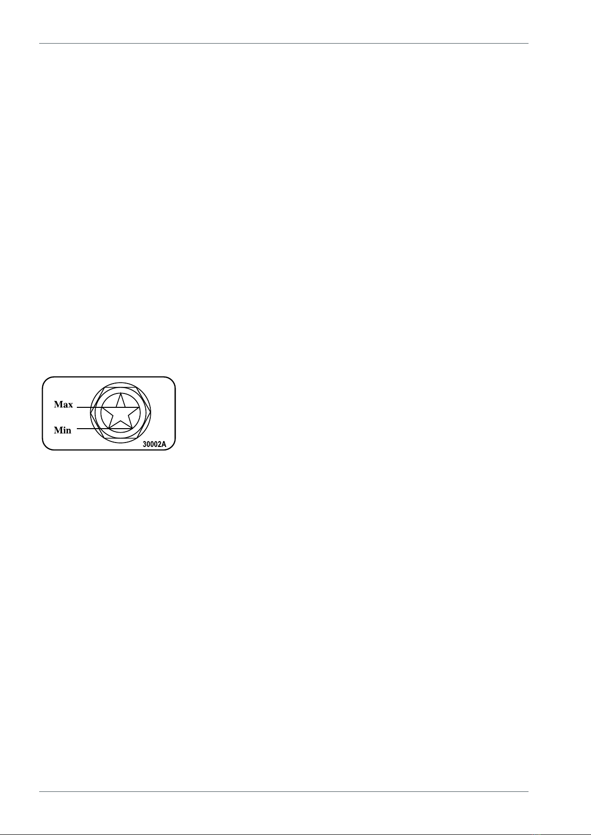
if necessary, top up hydraulic oil to the level with the upper edge of the level eye.
Kyltin numero 30002A
Kyltin koko (mm) 37 x 63 R5
Pohjan väri valkoinen
Tekstin (kuvion) väri musta
Tekstin korkeus 3,5 mm
Materiaali tarramuovi
Kiinnitystapa oma liima
Kiinnitysalusta maalattu teräslevy
Käyttöpaikka DINO 180XT, DINO 210XT, DINO 260XT
Lisätietoja
The hydraulic oil tank is located under a cover on the right-hand side of the lift.
At the same time, check in the level eye of the oil tank that the oil is looking clean and normal
(no excess foam etc.).
3.1.5. Check the hydraulic hoses, pipes and connectors
Check visually the hydraulic hoses, pipes and connections.
Make sure that there are no visible oil leaks.
Replaceanyexternallydamagedhosesandclashedpipesorttings.
Other manuals for DINO 260XTD
2
Table of contents
Other Dino lift Boom Lift manuals

Dino lift
Dino lift 240RXT Technical specifications

Dino lift
Dino lift DINO 280RXT User manual

Dino lift
Dino lift DINO 185XTC II User manual

Dino lift
Dino lift DINO 160XT II User manual

Dino lift
Dino lift 240RXT User manual

Dino lift
Dino lift DINO 185XTC II Instructions for use

Dino lift
Dino lift 135TB II User manual


