2
VIVAH - IP1776
IAVVERTENZE GENERALI PER LA SICUREZZA
Il presente manuale di installazione è rivolto esclusi-
vamente a personale professionalmente competente.
L’installazione, i collegamenti elettrici e le regolazioni devono
essere effettuati nell’osservanza della Buona Tecnica e in ot-
temperanza alle norme vigenti. Leggere attentamente le istru-
zioni prima di iniziare l’installazione del prodotto. Una errata
installazione può essere fonte di pericolo. I materiali dell’imbal-
laggio (plastica, polistirolo, ecc.) non vanno dispersi nell’am-
biente e non devono essere lasciati alla portata dei bambini in
quanto potenziali fonti di pericolo. Prima di iniziare l’installazio-
ne verificare l’integrità del prodotto. Non installare il prodotto in
ambiente e atmosfera esplosivi: presenza di gas o fumi infiam-
mabili costituiscono un grave pericolo per la sicurezza. I dispo-
sitivi di sicurezza (fotocellule, coste sensibili, stop di emergen-
za, ecc.) devono essere installati tenendo in considerazione: le
normative e le direttive in vigore, i criteri della Buona Tecnica,
l’ambiente di installazione, la logica di funzionamento del siste-
ma e le forze sviluppate dalla porta o cancello motorizzati.
Prima di collegare l’alimentazione elettrica accertarsi che
i dati di targa siano rispondenti a quelli della rete di di-
stribuzione elettrica. Prevedere sulla rete di alimentazione un
interruttore / sezionatore onnipolare con distanza d’apertura
dei contatti uguale o superiore a 3 mm. Verificare che a monte
dell’impianto elettrico vi sia un interruttore differenziale e una
protezione di sovracorrente adeguati. Quando richiesto, colle-
gare la porta o cancello motorizzati a un’efficace impianto di
messa a terra eseguito come indicato dalle vigenti norme di
sicurezza.
Durante gli interventi di installazione, manutenzione e ripara-
zione, togliere l’alimentazione prima di aprire il coperchio per
accedere alle parti elettriche.
La manipolazione delle parti elettroniche deve essere
effettuata munendosi di bracciali conduttivi antistatici col-
legati a terra. Il costruttore della motorizzazione declina ogni
responsabilità qualora vengano installati componenti incom-
patibili ai fini della sicurezza e del buon funzionamento. Per
l’eventuale riparazione o sostituzione dei prodotti dovranno es-
sere utilizzati esclusivamente ricambi originali.
AVVERTENZE DI INSTALLAZIONE
Fissare il quadro elettrico in modo permanente. Forare il con-
tenitore del quadro elettrico nel lato inferiore per il passaggio
dei cavi. Se accessibili, bloccare i cavi medianti opportuni pres-
sacavi (non di nostra fornitura). Mantenere separati di almeno
8 mm i conduttori di linea dai conduttori motori e comandi nei
punti di connessione alle morsettiere (per esempio con fascet-
te). Collegare insieme i conduttori di protezione (colore giallo/
verde) della linea, del trasformatore e del quadro elettronico
mediante il morsetto in dotazione. Al termine dell’installazione
richiudere il contenitore.
DICHIARAZIONE CE DI CONFORMITÀ
Fabbricante: DITEC S.p.A. - via Mons. Banfi, 3
21042 Caronno Pertusella (VA) – ITALY.
Dichiara che il quadro elettrico tipo VIVAH è conforme alle con-
dizioni delle seguenti direttive CE:
Direttiva bassa tensione 73/23/CEE;
Direttiva EMC 89/336/CEE.
Caronno Pertusella, Fermo Bressanini
21-10-2005 (Presidente)
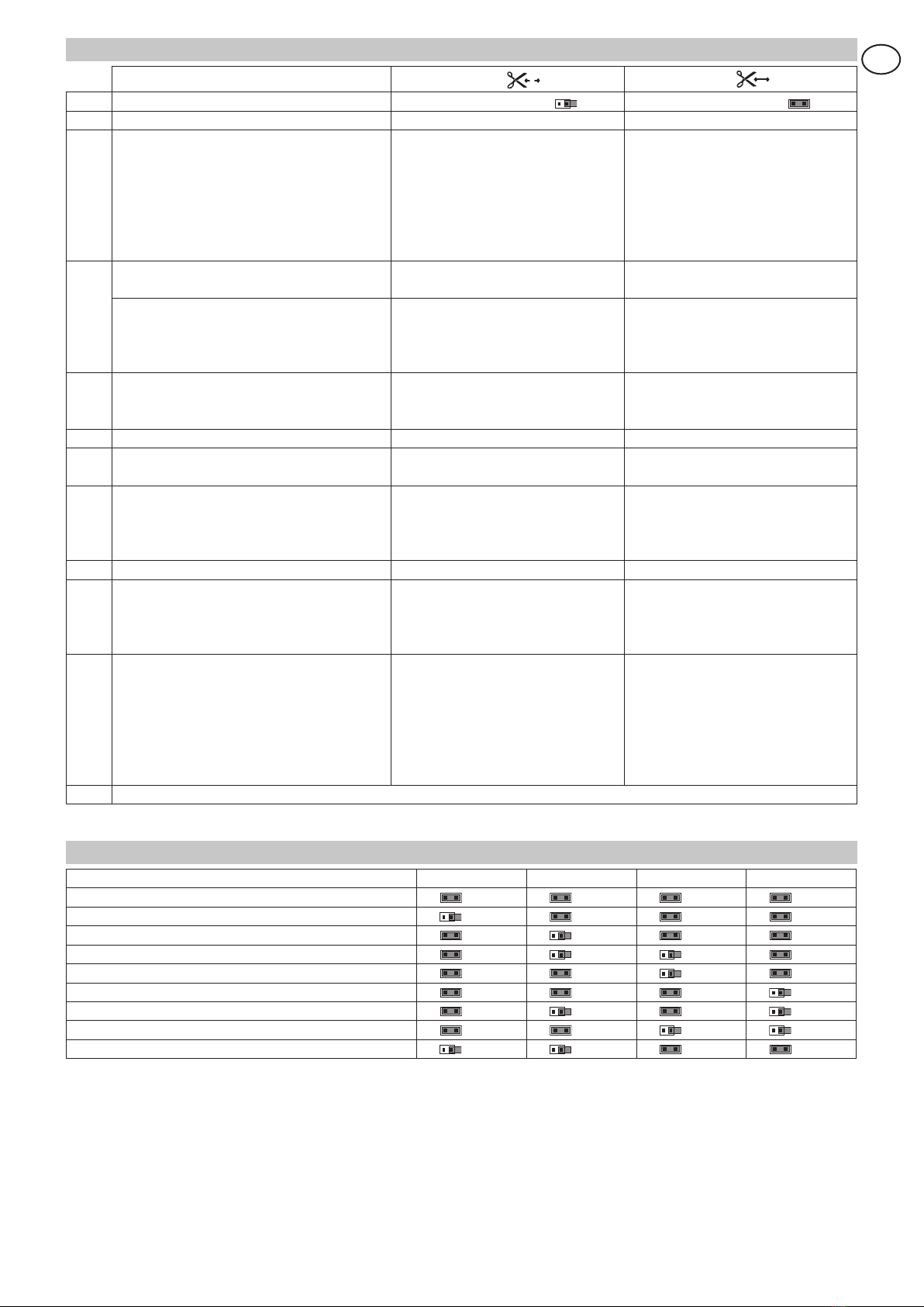
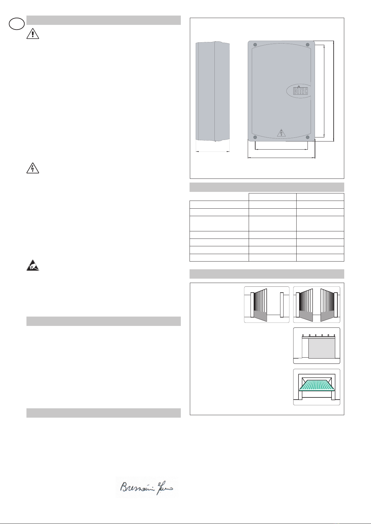
DATI TECNICI
VIVAH VIVAHJ
Alimentazione 230 V~ / 50-60 Hz 120 V~ / 50-60 Hz
Fusibile F1 F2A F4A
Uscita motore 24 V=
2x12 A max
24 V=
2x12 A max
Alimentazione accessori 24 V= / 0,5 A 24 V= / 0,5 A
Temperatura -20° C / +55° C -20° C / +55° C
Grado di protezione IP55 IP55
Dimensioni 238x357x120 238x357x120
Fig. 2
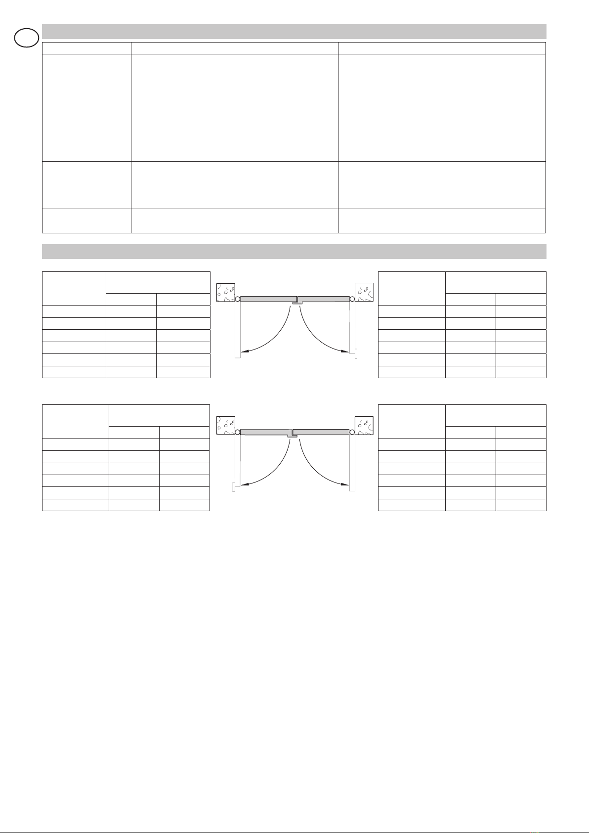
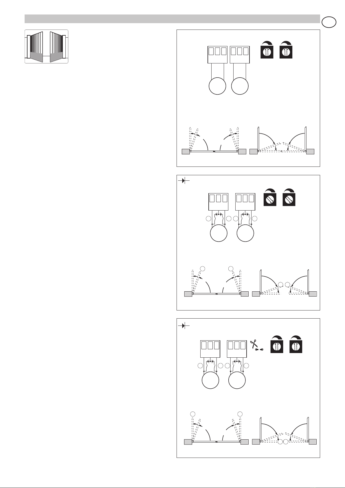
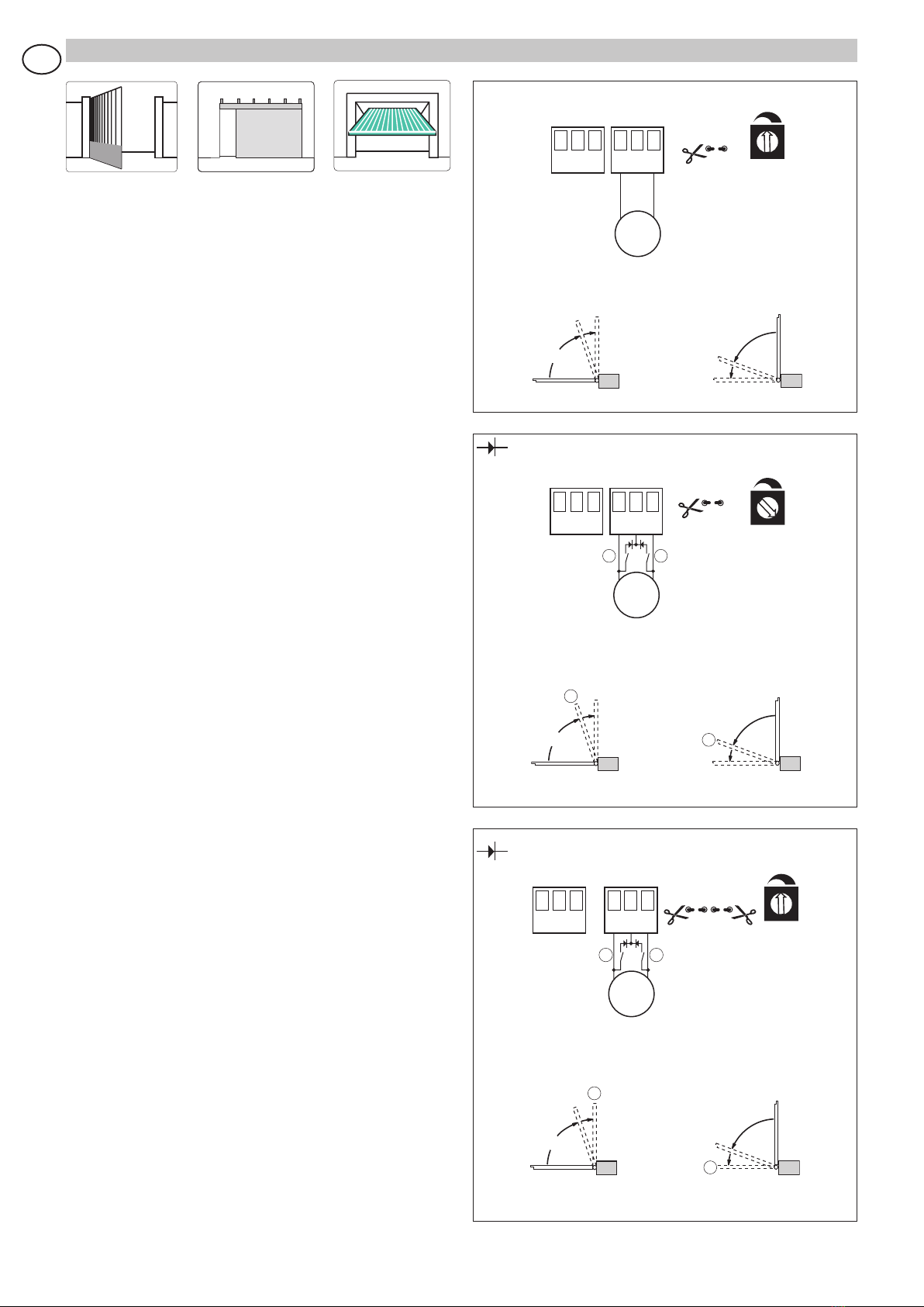
APPLICAZIONI
Tutti i diritti sono riservati
I dati riportati sono stati redatti e controllati con la massima
cura. Tuttavia non possiamo assumerci alcuna responsabilità
per eventuali errori, omissioni o approssimazioni dovute ad esi-
genze tecniche o grafiche.