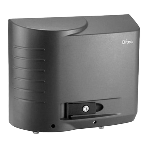
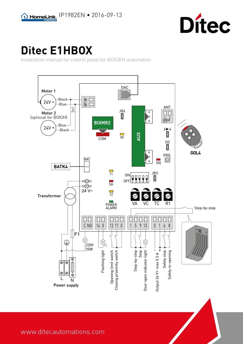
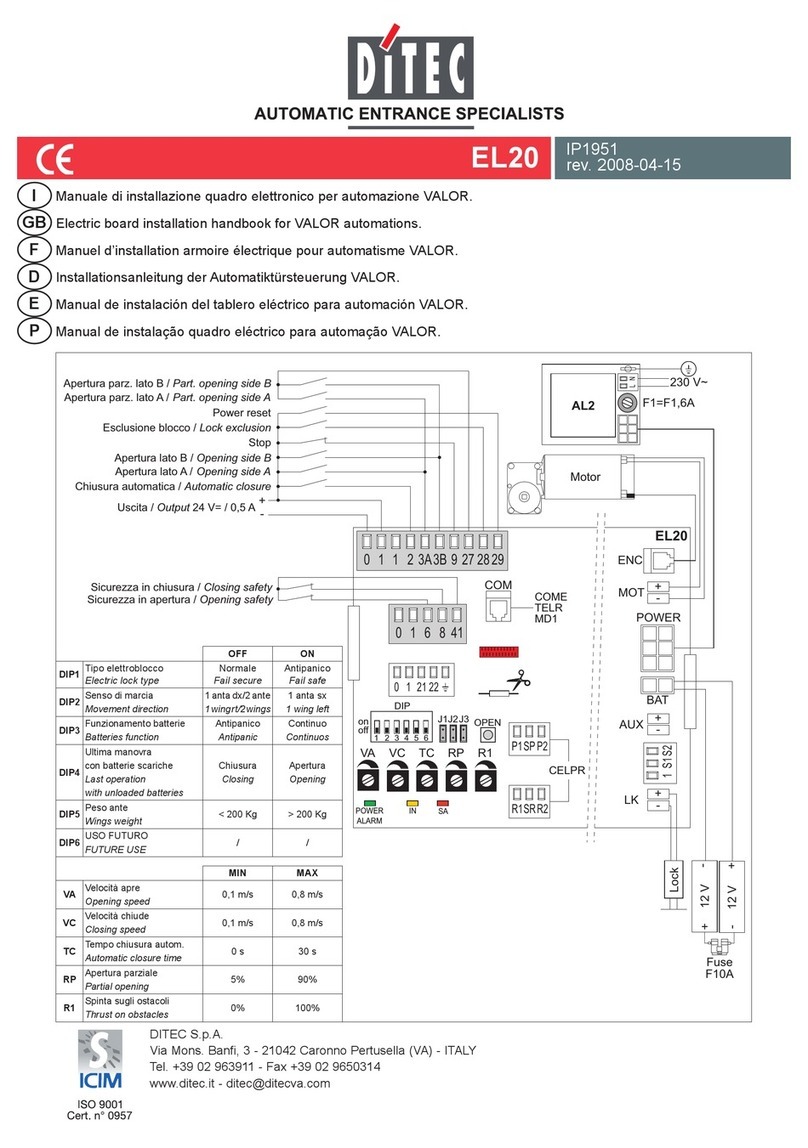
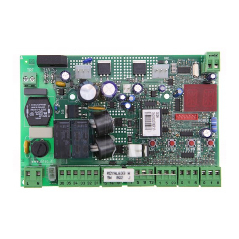
DITEC E1T User manual

DITEC S.p.A.
Via Mons. Banfi, 3 - 21042 Caronno Pertusella (VA) - ITALY
Tel. +39 02 963911 - Fax +39 02 9650314
www.ditec.it - [email protected]
E1T IP1897
rev. 2007-06-26
I
P
E
D
F
GB
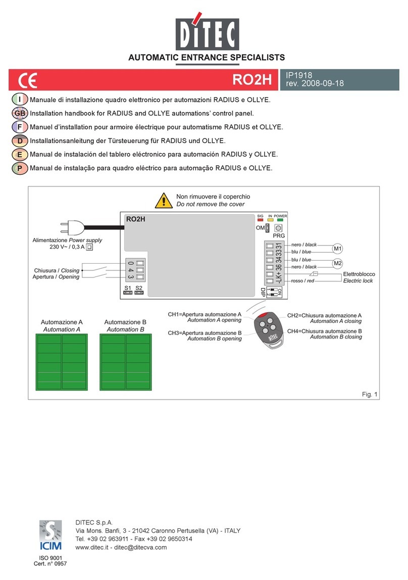
Manuale di installazione quadro elettronico per automazioni 400 V trifase a 1 motore.
Installation manual for control panel for 400 V three-phase automations with 1 motor.
Manuel d’installation du tableau électrique pour automatisme 400 V triphasé à 1 moteur.
Installationshandbuch Steuerung für Antriebe 400 V dreiphasig mit 1 Motor.
Manual de instalación cuadro electrónico para automatismos 400 V trifásicos de 1 motor.
Manual de instalação do quadro electrónico para automações 400 V trifásicas com 1 motor.
SO EO
TCRP
EL07L EL07PW1
on
off
111217
J7
1
SA POWERIN
Finecorsa apre / Opening limit switch
Lampeggiante / Flashing light
USO FUTURO / FUTURE USE
Finecorsa chiude / Closing limit switch
Termica motore / Thermal protection
Termica motore
Thermal protection
Arresto di sicurezza / Stop safety contact
Riapertura di sicurezza / Reversal safety contact
Chiusura automatica / Automatic closing
Apertura / Opening
Chiusura / Closing
Stop
Apertura parziale / Partial opening
Safety test
-
+
Uscita / Output 24 V= / 0,5 A
OPEN
TRANSF
OPEN
1 2 3 4 5 6
-LK+
171412 11 00 0 1 1 2 3 4 6 8 9 20 41
F4
U W V
M
3~
L3 L2 L1
L3 L2 L1
F3
Alimentazione
Power supply
F2 F1
COM
MIN MAX
TC Tempo chiusura automatica
Automatic closure time 0 s 120 s
RP Apertura parziale
Partial opening 0 s 30 s
OFF ON
DIP1 Funzionamento 1-3
1-3 operating mode
passo-passo
step by step
apertura
opening
DIP2 Rinnovo tempo chiusura aut.
Aut. closure time renewal 50% 100%
DIP3 Prelampeggio
Pre-operation flashing light
disabilitato
disabled
abilitato
enabled
DIP4 Tipo applicazione
Automation type
scorrevole o sezionale
sliding gate or sectional door
non usare
do not use
DIP5 Freno dinamico
Dynamic brake
disabilitato
disabled
non usare
do not use
DIP6 USO FUTURO
FUTURE USE /non usare
do not use

2
E1T - IP1897
IAVVERTENZE GENERALI PER LA SICUREZZA
Il presente manuale di installazione è rivolto esclusi-
vamente a personale professionalmente competente.
L’installazione, i collegamenti elettrici e le regolazioni devono
essere effettuati nell’osservanza della Buona Tecnica e in
ottemperanza alle norme vigenti. Leggere attentamente le
istruzioni prima di iniziare l’installazione del prodotto. Una
errata installazione può essere fonte di pericolo. I materiali
dell’imballaggio (plastica, polistirolo, ecc.) non vanno dispersi
nell’ambiente e non devono essere lasciati alla portata dei
bambini in quanto potenziali fonti di pericolo. Prima di iniziare
l’installazione verificare l’integrità del prodotto. Non installare
il prodotto in ambiente e atmosfera esplosivi: presenza di
gas o fumi infiammabili costituiscono un grave pericolo per la
sicurezza. I dispositivi di sicurezza (fotocellule, coste sensibili,
stop di emergenza, ecc.) devono essere installati tenendo in
considerazione: le normative e le direttive in vigore, i criteri
della Buona Tecnica, l’ambiente di installazione, la logica di
funzionamento del sistema e le forze sviluppate dalla porta o
cancello motorizzati.
Prima di collegare l’alimentazione elettrica accertarsi
che i dati di targa siano rispondenti a quelli della rete di
distribuzione elettrica. Prevedere sulla rete di alimentazione
un interruttore/sezionatore onnipolare con distanza d’apertura
dei contatti uguale o superiore a 3 mm. Verificare che a monte
dell’impianto elettrico vi sia un interruttore differenziale e una
protezione di sovracorrente adeguati. Quando richiesto, colle-
gare la porta o cancello motorizzati a un’efficace impianto di
messa a terra eseguito come indicato dalle vigenti norme di
sicurezza. Durante gli interventi di installazione, manutenzione
e riparazione, togliere l’alimentazione prima di aprire il coper-
chio per accedere alle parti elettriche.
La manipolazione delle parti elettroniche deve essere
effettuata munendosi di bracciali conduttivi antistatici col-
legati a terra. Il costruttore della motorizzazione declina ogni
responsabilità qualora vengano installati componenti incom-
patibili ai fini della sicurezza e del buon funzionamento. Per
l’eventuale riparazione o sostituzione dei prodotti dovranno
essere utilizzati esclusivamente ricambi originali.
AVVERTENZE DI INSTALLAZIONE
Fissare il quadro elettrico in modo permanente. Effettuare il
passaggio dei cavi nel lato inferiore del contenitore.
Se accessibili, bloccare i cavi medianti opportuni pressacavi
(non di nostra fornitura). Mantenere separati di almeno 8 mm i
conduttori di linea e motore dai conduttori comandi nei punti di
connessione alle morsettiere (per esempio con fascette).
Collegare insieme i conduttori di protezione (colore giallo/ver-
de) della linea e dei motori mediante il morsetto in dotazione.
Al termine dell’installazione richiudere il contenitore.
DICHIARAZIONE CE DI CONFORMITÀ
Fabbricante: DITEC S.p.A.
Indirizzo: via Mons. Banfi, 3
21042 Caronno P.lla (VA) – ITALY.
Dichiara che il quadro elettronico tipo E1T è conforme alle con-
dizioni delle seguenti direttive CE:
Direttiva bassa tensione 73/23/CEE;
Direttiva EMC 89/336/CEE.
Caronno Pertusella, Fermo Bressanini
08-01-2007 (Presidente)
DATI TECNICI
APPLICAZIONI
E1T
Alimentazione 400 V~ / 50Hz
Fusibile F1, F2, F3 F8A
Fusibile F4 F3,15A
Uscita motore 400 V~ / 6 A max
Alimentazione accessori 24 V= / 0,5 A
Temperatura -20° C / +55° C
Grado di protezione IP55
Dimensioni 238x357x120
210
238
120
328
357
E1T

3E1T - IP1897
I
1. COLLEGAMENTI ELETTRICI
1.1 Comandi
Comando Funzione Descrizione
1 2 N.O. CHIUSURA AUTOMATICA La chiusura permanente del contatto abilita la chiusura automatica.
1 3 N.O. APERTURA Con DIP1=ON la chiusura del contatto attiva la manovra di aper-
tura.
PASSO PASSO Con DIP1=OFF la chiusura del contatto attiva una manovra di aper-
tura o chiusura in sequenza: apre-stop-chiude-apre.
N.B.: se la chiusura automatica è abilitata, lo stop non è permanen-
te ma della durata impostata da TC.
1 4 N.O. CHIUSURA La chiusura del contatto attiva la manovra di chiusura.
41 6 N.C. ARRESTO DI SICUREZZA L’apertura del contatto arresta e/o impedisce qualsiasi manovra.
41 8 N.C. SICUREZZA DI
INVERSIONE
L’apertura del contatto di sicurezza provoca l’inversione del movi-
mento (riapertura) durante la fase di chiusura.
1 9 N.C. STOP L’apertura del contatto di sicurezza provoca l’arresto del movimen-
to.
ARRESTO DI EMERGENZA Per ottenere un arresto di emergenza (ad esempio mediante l’ap-
posito pulsante rosso) collegare i comandi di apertura e chiusura al
morsetto 9 anzichè 1 (9-3, 9-4, 9-20).
1 9 N.O. COMANDO A UOMO
PRESENTE
L’apertura permanente del contatto di sicurezza abilita la funzione
a uomo presente.
In questa condizione, i comandi di apertura (1-3/1-20) e di chiusura
(1-4) funzionano solo se mantenuti premuti, al loro rilascio l’auto-
mazione si ferma.
Le eventuali sicurezze presenti, il comando passo-passo e la chiu-
sura automatica sono disabilitati.
1 20 APERTURA PARZIALE La chiusura del contatto attiva una manovra di apertura parziale
della durata impostata mediante il trimmer RP.
Ad automazione ferma il comando di apertura parziale effettua la
manovra opposta a quella precedente all’arresto.
0 11 N.C. FINECORSA CHIUDE L’apertura del contatto del finecorsa arresta il movimento di chiu-
sura.
0 12 N.C. FINECORSA APRE L’apertura del contatto del finecorsa arresta il movimento di aper-
tura.
17 USO FUTURO
ATTENZIONE: Ponticellare tutti i contatti N.C. se non utilizzati. I morsetti con numero uguale sono equivalenti. La garanzia di
funzionamento e le prestazioni dichiarate si ottengono solo con accessori e dispositivi di sicurezza DITEC.
1.2 Costa di sicurezza autocontrollata SOFA1-SOFA2
Comando Funzione Descrizione
1 6 N.C. ARRESTO DI SICUREZZA Collegare il contatto di uscita del dispositivo SOFA1-SOFA2 ai morsetti
1-6 del quadro elettronico (in serie al contatto di uscita della fotocellula,
se presente).
1 8 N.C. SICUREZZA DI INVERSIONE Collegare il contatto di uscita del dispositivo SOFA1-SOFA2 ai morsetti
1-8 del quadro elettronico (in serie al contatto di uscita della fotocellula,
se presente).
41 SAFETY TEST Collegare il morsetto 41 di controllo della sicurezza al morsetto 41 del
dispositivo SOFA1-SOFA2. Mediante il morsetto 41 viene attivato un
test della costa di sicurezza prima di ogni manovra. Se il test fallisce il
led SA lampeggia e il test viene ripetuto.

4
E1T - IP1897
I1.3 Uscite e accessori
2. REGOLAZIONI
2.1 Trimmer
Trimmer Descrizione
TC
MIN=0 s MAX=120 s
Regolazione tempo chiusura automatica. Da 0 a 120 s.
N.B.: dopo l’attivazione del comando di stop, alla richiusura del contatto 1-9, la chiusura automatica si
abilita solo dopo un comando di apertura totale, parziale o passo-passo.
RP
0 s 30 s
Regolazione apertura parziale motore. Da 0 a 30 s.
PT3PT4
Uscita Valore Descrizione
1 +
0 - 24 V= / 0,5 A Alimentazione accessori. Uscita per alimentazione accessori esterni comprese
lampade stato automazione.
1 11 24 V= / 3 W
(0,125 A)
Lampada automazione aperta. La luce si spegne quando l’automazione è
chiusa.
1 12 24 V= / 3 W
(0,125 A)
Lampada automazione chiusa. La luce si spegne quando l’automazione è
aperta.
0 14 24V= / 50 W
(2 A)
Lampeggiante (LAMPH). Si attiva durante le manovre di apertura e chiusura.
- LK + /NON USARE
M
3~
U VW
400 V~ / 6 A
Motore trifase.
Collegare il contatto della termica motore in serie ai finecorsa.
N.B.: se la rotazione del motore non corrisponde al corretto senso di marcia invertire
le fasi di alimentazione L2 e L3.
Pulsantiera a membrana (PT3). Attiva la manovra di apertura.
N.B.: collegare il connettore della pulsantiera a J7 come indicato nell’esempio di
fig. 6.1. Per attivare la manovra di chiusura collegare il connettore della pulsantiera
a J7 ruotato di 180°.
Pulsantiera a membrana (PT3). Provoca l’arresto del movimento.
Pulsantiera a membrana (PT3). Attiva la manovra di chiusura.
N.B.: collegare il connettore della pulsantiera a J7 come indicato nell’esempio di
fig. 6.1. Per attivare la manovra di apertura collegare il connettore della pulsantiera
a J7 ruotato di 180°.
ON
Pulsantiera a membrana (PT4). Attiva la manovra di apertura.
N.B.: il led verde acceso segnala la presenza di alimentazione 24 V=.
Pulsantiera a membrana (PT4). Attiva la manovra di apertura parziale.
Pulsantiera a membrana (PT4). Attiva e disattiva la funzione di STOP.
N.B.: il led rosso acceso segnala l’attivazione dello STOP. Il led rosso lampeggiante
segnala l’attivazione delle sicurezze.
Pulsantiera a membrana (PT4). Attiva la manovra di chiusura.

5E1T - IP1897
I
2.2 Dip-Switch
Descrizione OFF ON
DIP1 Funzionamento comando 1-3. Passo-Passo. Apertura.
DIP2 Rinnovo tempo chiusura auto-
matica.
50% 100%
DIP3 Prelampeggio fisso di 3 s. Disabilitato in apertura.
Abilitato solo con chiusura automatica con
TC>3 s.
Abilitato sia in apertura che in chiusura.
DIP4 Tipologia applicazione. Cancello scorrevole o porta sezionale. NON USARE
DIP5 Freno dinamico. Disabilitato. NON USARE
DIP6 USO FUTURO / NON USARE
2.3 Ponticelli
Descrizione OFF ON
SO Funzionamento sicurezza di in-
versione
Ad automazione ferma, se il contatto 41-8
è aperto, è possibile attivare la manovra
di apertura.
Ad automazione ferma, se il contatto 41-8 è
aperto, viene impedita qualsiasi manovra.
EO NON USARE / /
2.4 Segnalazioni
LED Acceso Lampeggiante
POWER Presenza di alimentazione 24 V=. /
SA Indica che almeno uno dei contatti di sicurezza è
aperto.
- Indica la funzione di STOP attivata da pulsantiera
PT4 (se presente).
- Nel caso di utilizzo di dispositivo SOFA1-SOFA2,
indica il fallimento del test di sicurezza (morsetto
41).
- All’accensione il LED lampeggia indicando il
conteggio delle manovre effettuate:
ogni lampeggio veloce = 1000 manovre
ogni lampeggio lento = 10000 manovre
IN Si accende ad ogni comando e ad ogni variazione
di dip-switch e ponticelli. /
11 Indica che il contatto del finecorsa 0-11 é aperto. /
12 Indica che il contatto del finecorsa 0-12 é aperto. /
17 USO FUTURO
3. AVVIAMENTO
ATTENZIONE: Le manovre relative al punto 3.3 avvengono senza sicurezze.
3.1 Ponticellare i contatti di sicurezza N.C.
3.2 Impostare DIP4=OFF.
3.3 Dare alimentazione.
Dare dei comandi di apertura e chiusura e verificare il corretto funzionamento dell’automazione e la corretta regolazione dei
finecorsa.
N.B.: se la rotazione del motore non corrisponde al corretto senso di marcia invertire le fasi di alimentazione L2 e L3.
3.4 Collegare i dispositivi di sicurezza (rimuovendo i relativi ponticelli) e verificarne il corretto funzionamento.
N.B.: verificare che le forze operative delle ante siano conformi a quanto richiesto dalle norme EN12453-EN12445.
3.5 Se desiderato, attivare la chiusura automatica e regolarla mediante il trimmer TC.
3.6 Se desiderato, impostare con RP l’apertura parziale.
3.7 Se desiderato, collegare la ricevente radio nell’apposito connettore OPEN, programmare i trasmettitori come indicato nel
relativo manuale e verificarne il funzionamento.
3.8 Collegare eventuali altri accessori e verificarne il funzionamento.
3.9 Terminati l’avviamento e le verifiche richiudere il contenitore.

6
E1T - IP1897
I
5. ESEMPIO DI APPLICAZIONE PER CANCELLI SCORREVOLI
4. RICERCA GUASTI
Problema Possibile causa Intervento
L’automazione non apre e non
chiude
Manca alimentazione.
(led POWER spento).
Verificare che il quadro elettronico sia corretta-
mente alimentato.
Accessori in corto circuito.
(led POWER spento).
Scollegare tutti gli accessori dai morsetti 0-1
(deve essere presente tensione 24 V=) e ricolle-
garli uno alla volta.
Fusibili di linea bruciati.
(led POWER spento).
Sostituire i fusibili.
I contatti di sicurezza sono aperti.
(led SA acceso).
Verificare che i contatti di sicurezza siano corret-
tamente chiusi (N.C.).
I contatti di sicurezza non sono collegati
correttamente oppure la costa di sicurezza
autocontrollata SOFA1-SOFA2 non funziona
correttamente. (led SA lampeggiante).
Verificare i collegamenti ai morsetti 6-8 del quadro
elettronico e i collegamenti alla costa di sicurezza
autocontrollata SOFA1-SOFA2.
Microinterruttore di sblocco aperto (dove pre-
sente).
Verificare la corretta chiusura dello sportello e il
contatto del microinterruttore.
La termica del motore è aperta.
(led 11 e 12 accesi).
Verificare la continuità del contatto termico.
L’automazione apre ma non
chiude
I contatti di sicurezza sono aperti.
(led SA acceso).
Verificare che i contatti di sicurezza siano corret-
tamente chiusi (N.C.).
I contatti di sicurezza non sono collegati
correttamente oppure la costa di sicurezza
autocontrollata SOFA1-SOFA2 non funziona
correttamente. (led SA lampeggiante).
Verificare i collegamenti ai morsetti 6-8 del quadro
elettronico e i collegamenti alla costa di sicurezza
autocontrollata SOFA1-SOFA2.
Le fotocellule sono attivate.
(led SA acceso).
Verificare la pulizia e il corretto funzionamento
delle fotocellule.
La chiusura automatica non funziona. Verificare che il contatto 1-2 sia chiuso.
Le sicurezze esterne non inter-
vengono
Collegamenti errati tra le fotocellule e il qua-
dro elettronico.
Collegare i contatti di sicurezza N.C. in serie tra
loro e levare gli eventuali ponticelli presenti sulla
morsettiera del quadro elettronico.
Quando il quadro elettronico viene usato in applicazioni per
automazioni scorrevoli:
- impostare DIP4=OFF;
- (Fig. 5.1) collegare i contatti N.C. dei finecorsa di apertura
e chiusura ai morsetti 0-11-12.
Con questi collegamenti, l’anta si ferma quando intervengono
i finecorsa.
N.B.: nel caso di utilizzo della costa di sicurezza autocontrolla-
ta SOFA1-SOFA2 effettuare i collegamenti indicati al capitolo
1.2.
N.B.: E’ possibile usare il comando radio con funzionamento
passo-passo e contemporaneamente il morsetto 3 con funzione
di apertura eseguendo i collegamenti indicati in fig. 5.2 e impo-
stando DIP1=OFF.
Fig. 5.1
ON
DIP4=OFF
OFF
Limit switch
Limit switch
Thermal protection
1 2 3 4 5 6
171412 11 00 0 1 1 2 3 4 6 8 9 20 41
ON
DIP1/DIP4=OFF
OFF 1 2 3 4 5 6
171412 11 00 0 1 1 2 3 4 6 8 9 20 41
Fig. 5.2

7E1T - IP1897
I
6. ESEMPIO DI APPLICAZIONE PER SEZIONALI
Fig. 6.1
Fig. 6.2
(Fig. 6.1) Quando il quadro elettronico viene usato in applicazioni
per automazioni sezionali:
- impostare DIP1=ON;
- impostare DIP2=ON;
- impostare DIP4=OFF;
- collegare i contatti N.C. dei finecorsa di apertura e chiusura
ai morsetti 0-11-12;
N.B.: se si vuole utilizzare il quadro elettronico in modalità a
uomo presente, scollegare il morsetto 9.
In questa condizione, i comandi di apertura (1-3, 1-20) e di chiu-
sura (1-4) funzionano solo se mantenuti premuti, al loro rilascio
l’automazione si ferma. La chiusura automatica e i comandi
radio sono disabilitati.
(Fig. 6.2) Se si collega la costa di sicurezza autocontrollata
SOFA1 - SOFA2 in chiusura, effettuare i collegamenti indicati
in figura.
Attenzione: se la costa in chiusura rimane premuta sul pavimen-
to, tagliare il ponticello SO.
N.B.: è possibile collegare al connettore J7 la pulsantiera PT3
(fig. 6.1) oppure la pulsantiera PT4 (fig. 6.2).
DIP4=OFF
DIP1=ON
DIP2=ON
ON
J7
1
OFF 123456
Limit switch
Limit switch
Thermal protection
171412 11 00 0 1 1 2 3 4 6 8 9 20 41
DIP4=OFF
DIP1=ON
DIP2=ON
ON
J7 OFF 123456
Limit switch
Limit switch
Thermal protection
Safety test SOFA1-SOFA2
171412 11 00 0 1 1 2 3 4 6 8 9 20 41
ON
1
SO

8
E1T - IP1897
I7. ESEMPIO DI AUTOMAZIONI IN PARALLELO
A
B
E’ possibile comandare due automazioni [A] e [B] in parallelo,
facendo i collegamenti indicati in figura 7.1.
Per gestire entrambe le automazioni con un unico comando
radio inserire una ricevente BIXLR22.
La chiusura automatica si ottiene collegando i morsetti 1-2 e
regolando il trimmer TC nella stessa posizione in entrambi i
quadri elettronici.
Se si usa l’apertura parziale 1-20, regolare il trimmer RP nella
stessa posizione in entrambi i quadri elettronici.
N.B.: i movimenti di apertura e chiusura non sono sincronizzati.
Attenzione: in assenza di costa di sicurezza SOFA1-SOFA2
collegare i comandi 1-6 e 1-8 alla scheda SWT
Le eventuali pulsantiere a membrana PT3/PT4 collegate al
quadro elettronico E1T aprono/chiudono solo l’automazione a
cui sono collegate.
A
B
BIXLR22
NO RADIO
1
23468
9
20
41
41
209864
3
2
1
OUT2
JR1 JR2
JR1=NO
JR2=CH1
SWT
SWT
6 80 41
6 8
6 8
6 80 41
DIP1=ONDIP1=ON
1 2
3
4
5
6
1 2
3
4
5
6
Fig. 7.1

GB
9E1T - IP1897
GENERAL SAFETY PRECAUTIONS
This installation manual is intended for professionally
competent personnel only.
The installation, the power connections and the settings must
be completed in conformity with Good Working Methods and
with the regulations in force. Before installing the product, care-
fully read the instructions. Bad installation could be hazardous.
The packaging materials (plastic, polystyrene, etc.) should not
be discarded in the environment or left within reach of children,
as these are a potential source of hazard. Before beginning the
installation check that the product is in perfect condition.
Do not install the product in explosive areas and atmospheres:
the presence of flammable gas or fumes represents a serious
threat to safety.
The safety devices (photocells, sensitive edges, emergency
stop, etc.) must be installed taking into account: the provisions
and the directives in force, Good Working Methods, the instal-
lation area, the functional logic of the system and the forces
developed by the motorised door or gate.
Before making power connections, check that the rating
corresponds to that of the mains supply A multipolar di-
sconnection switch with a contact opening gap of at least 3 mm
must be included in the mains supply. Check that upstream of
the electrical installation an adequate residual current circuit
breaker and an overcurrent cut out are fitted. When requested,
connect the motorised door or gate to an effective earthing
system carried out as indicated by current safety regulations.
During installation, maintenance and repair operations, cut
off the power supply before opening the cover to access the
electrical parts.
To handle electronic parts, wear earthed antistatic con-
ductive bracelets. The manufacturer of the motorisation
declines all responsibility in the event of components which
are not compatible with the safe and correct operation of the
product. For repairs or replacements of products only original
spare parts must be used.
INSTALLATION WARNING
Secure the control panel permanently. Drill a hole into the lower
side of the container so as to run the cables through it. Secure
the cables, if they are accessible, by means of appropriate
gland plates (not provided by us). Keep the line and motor con-
ductors separate (at least 8 mm) from the control conductors at
the terminal board connection points (for example, by means
of clamps). Connect the line and motor protection conductors
(yellow-green) by means of the transformer and control panel
using the clamp provided. At the end of the installation to close
again the container.
EC DECLARATION OF CONFORMITY
Manufacturer: DITEC S.p.A.
Address: via Mons. Banfi, 3
21042 Caronno P.lla (VA) – ITALY.
Herewith declares that the control panel E1T is in conformity
with the provisions of the following EC directives:
Low Voltage Directive 73/23/EEC;
EMC Directive 89/336/EEC.
Caronno Pertusella, Fermo Bressanini
08-01-2007 (President)
TECHNICAL DETAILS
APPLICATIONS
E1T
Power supply 400 V~ / 50Hz
Fuse F1, F2, F3 F8A
Fuse F4 F3,15A
Motor output 400 V~ / 6 A max
Accessories power
supply 24 V= / 0,5 A
Temperature -20° C / +55° C
Protection degree IP55
Dimensions 238x357x120
210
238
120
328
357
E1T

10
E1T - IP1897
GB 1. ELECTRICAL CONNECTIONS
1.1 Commands
Command Function Description
1 2 N.O. AUTOMATIC CLOSING Permanently closing the contact enables automatic closing.
1 3 N.O. OPENING With DIP1=ON the closure of the contact activates an opening ope-
ration.
STEP-BY-STEP With DIP1=OFF the closure of the contact activates an opening or
closing operation in the following sequence: open-stop-close-open.
Note: if automatic closing is enabled, the stop is not permanent but
at a time that is set by the TC.
1 4 N.O. CLOSING The closing manoeuvre starts when the contact is closed.
41 6 N.C. SAFETY STOP All operations are stopped and/or blocked when the contact is opened.
41 8 N.C. REVERSAL SAFETY DEVICE Opening the safety contact triggers a reversal of the movement
(reopening) during a closing operation.
1 9 N.C. STOP Opening the safety contact stops the current operation.
EMERGENCY STOP To enable the emergency stop function (e.g. with a specific red but-
ton), connect the opening and closing controls to terminal 9 instead
of 1 (9-3, 9-4, 9-20).
1 9 N.O. HOLD TO RUN FUNCTION Permanently opening the safety contact enables the operator pre-
sence dependent function.
In this state, the opening (1-3/1-20) and closing (1-4) controls fun-
ction only if held in the pressed position, and the automation stops
when the controls are released.
All safety switches, the step-by-step control and the automatic clo-
sing function are disabled.
1 20 PARTIAL OPENING The closing of the contact activates a partial opening operation of
the duration set with the RP trimmer.
Once the automation stops, the partial opening control performs
the opposite operation to the one performed before stoppage.
0 11 N.C. CLOSURE LIMIT SWITCH The opening of the limit switch contact stops the closure operation.
0 12 N.C. OPENING LIMIT SWITCH The opening of the limit switch contact stops the opening operation.
17 FUTURE USE
WARNING: Make a jumper on all NC contacts if not in use. The terminals with the same number are equal. The given operating
and performance features can only be guaranteed with the use of DITEC accessories and safety devices.
1.2 Self-controlled safety edge SOFA1-SOFA2
Command Function Description
1 6 N.C. SAFETY STOP Connect the output contact of device SOFA1-SOFA2 to terminals 1-6
on the control panel (in series with the photocell output contact, if
installed).
1 8 N.C. REVERSAL SAFETY DEVICE Connect the output contact of device SOFA1-SOFA2 to terminals 1-8
on the control panel (in series with the photocell output contact, if
installed).
41 SAFETY TEST Connect the terminal of device SOFA1-SOFA2 to terminal 41 of the
control panel. Connecting terminal 41 enables a safety edge test cycle
before every operation. If the test fails the SA led flashes and the test
is repeated.

GB
11 E1T - IP1897
1.3 Outputs and accessories
Output Value Description
1 +
0 - 24 V= / 0,5 A Accessories power supply. Power supply output for external accessories, inclu-
ding automation status lamp.
1 11 24 V= / 3 W
(0,125 A)
Automation open lamp. The light switch off when the automation is closed.
1 12 24 V= / 3 W
(0,125 A)
Automation closed lamp. The light switches off when the automation is open.
0 14 24V= / 50 W
(2 A)
Flashing light (LAMPH). Activated during opening and closing operations.
-LK+ DO NOT USE
M
3~
U VW
400 V~ / 6 A
Three-phase motor.
Connect the contact of the motor circuit breaker in series to the limit switch.
Note: if the direction of rotation of the motor is incorrect for the desired direction
of movement, swap the L2 and L3 phases.
Membrane push-button panel (PT3). Starts the opening operation.
N.B.: connect the push-button panel connector to J7 as indicated in fig. 6.1.
Connect the push-button panel to J7 rotated through 180° to activate the closing
operation.
Membrane push-button panel (PT3). Causes the blocking of the movement.
Membrane push-button panel (PT3). Starts the closing operation.
Note: connect the push-button panel connector to J7 as indicated in fig. 6.1.
Connect the push-button panel to J7 rotated through 180° to activate the opening
operation.
ON
Membrane push-button panel (PT4). Starts the opening operation.
Note: the green LED on indicates the presence of the 24 V=power supply.
Membrane push-button panel (PT4). Starts the partial opening operation.
Membrane push-button panel (PT4). Starts and stops the STOP operation.
Note: the red LED on indicates that the STOP has been activated. the flashing red
LED indicates that the safety devices have been activated.
Membrane push-button panel (PT4). Starts the closing operation.
2. SETTINGS
2.1 Trimmer
Trimmer Description
TC Setting automatic closing time. From 0 to 120 s.
Note: after the activation of the stop command, once contact 1-9 has closed again, the automatic clo-
sing is only activated after a total, partial or step-by-step opening command.
RP Motor partial opening adjustment. From 0 to 30 s.
0 s 30 s
MIN=0 s MAX=120 s
PT3PT4

12
E1T - IP1897
GB 2.2 Dip-Switches
Description OFF ON
DIP1 Control 1-3 function. Step-by-Step. Opening.
DIP2 Restore automatic closing time. 50% 100%
DIP3 Preflashing set at 3 s. Disabled during opening.
Enabled only with automatic closing with TC
>3 s.
Enabled for both opening and closing.
DIP4 Application type. Sliding gate or sectional door. DO NOT USE
DIP5 Dynamic brake. Disabled. DO NOT USE
DIP6 FUTURE USE / DO NOT USE
2.3 Bridges
Description OFF ON
SO Reversal safety switch function. With the automation blocked, if the contacts
1-8 or 41-8 are open, it is possible to
activate the opening operation.
With the automation blocked, if the con-
tacts 1-8 or 41-8 are open, any operation
is impossible.
EO DO NOT USE / /
2.4 Signals
LED ON Flashing
POWER 24 V= power supply. /
SA Indicates that at least one of the safety contacts
is open.
- Indicates the STOP operation activated by push-
button panel PT4 (if present).
- If the SOFA1-SOFA2 device is installed, this
indicates a safety test failure (terminal 41).
- On power on, the LED flashes to indicate the
number of operations performed:
each rapid flash = 1000 operations
each slow flash = 10000 operations
IN Activated at every command and adjustment to
the dip-switch and jumper. /
11 Indicates that the 0-11 limit switch contact is open. /
12 Indicates that the 0-12 limit switch contact is open. /
17 FUTURE USE
3. STARTING
ATTENTION: The operations regarding point 3.3 are without safety devices.
3.1 Bridge the NC safety contacts with a jumper.
3.2 Set DIP4=OFF.
3.3 Switch on power.
Perform opening and closing commands and check that the automation functions correctly and that the limit switches are
correctly set.
Note: if the direction of rotation of the motor is incorrect for the desired direction of movement, swap the L2 and L3 phases.
3.4 Connect the safety devices (removing the relative jumpers) and check that they function correctly.
Note: ensure that the forces exerted by the door wings are compliant with EN12453-EN12445 regulations.
3.5 If required, activate automatic closing and adjust with the TC trimmer.
3.6 Set the partial opening with RP if required.
3.7 If required, connect the radio receiver to the relative OPEN connector, programme the transmitters as described in the relative
manual and check that all elements function correctly.
3.8 Connect any other accessories and check operation.
3.9 Once the start up and check procedures are completed, close the container.

GB
13 E1T - IP1897
5. EXAMPLE APPLICATIONS FOR SLIDING GATES
4. TROUBLESHOOTING
Problem Possible causes Remedy
Automation does not open or
close.
No power.
(POWER led off).
Check that the control panel is powered cor-
rectly.
Short circuited accessories.
(POWER led off).
Disconnect all accessories from terminals 0-1 (vol-
tage must be 24 V=) and reconnect one at a time.
Blown line fuse.
(POWER led off).
Replace fuse.
Safety contacts are open.
(SA led on).
Check that the safety contacts are closed correctly
(N.C.).
Safety contacts not correctly connected or
self-controlled safety edge SOFA1-SOFA2 not
functioning correctly.
(SA led flashing).
Check connections to terminals 6-8 on control
panel and connections to the self-controlled safety
edge SOFA1-SOFA2.
Release microswitch open.
(if present).
Check that the hatch is closed correctly and the
microswitch makes contact.
The motor thermal overload switch is open.
(11 and 12 led on).
Check the continuity of the thermal contact.
Automation opens but does not
close.
Safety contacts are open.
(SA led on).
Check that the safety contacts are closed correctly
(N.C.).
Safety contacts not correctly connected or
self-controlled safety edge SOFA1-SOFA2 not
functioning correctly.
(SA led flashing).
Check connections to terminals 6-8 on control
panel and connections to the self-controlled safety
edge SOFA1-SOFA2.
Photocells activated.
(SA led on).
Check that the photocells are clean and operating
correctly.
The automatic closing does not work. Check that contact 1-2 is closed.
External safety devices not ac-
tivating.
Incorrect connections between the photocells
and the control panel.
Connect NC safety devices together in series and
remove any bridges on the control panel terminal
board.
When control panel is used for sliding automations operations:
- set DIP4=OFF;
- (Fig. 5.1) connect opening and closing limit switches N.C.
contacts to plug 0-11-12.
With the above connections, when limit switches operate the
wing stops.
Note: if the self-controlled safety edge SOFA1-SOFA2 is used,
make the connections indicated in chapter 1.2.
N.B. It is possible to use the remote control with step-by-step
functioning and, at the same time, the terminal 3 with opening
function, making the connections indicated in fig. 5.2 and set-
ting DIP1=OFF.
Fig. 5.1
ON
DIP4=OFF
OFF
Limit switch
Limit switch
Thermal protection
1 2 3 4 5 6
171412 11 00 0 1 1 2 3 4 6 8 9 20 41
ON
DIP1/DIP4=OFF
OFF 1 2 3 4 5 6
171412 11 00 0 1 1 2 3 4 6 8 9 20 41
Fig. 5.2

14
E1T - IP1897
GB 6. EXAMPLE OF APPLICATION FOR SECTIONAL OVERHEAD DOORS
Fig. 6.1
Fig. 6.2
(Fig. 6.1) When the control panel is used in applications for
sectional automations:
- set DIP1=ON;
- set DIP2=ON;
- set DIP4=OFF;
- connect opening and closing limit switches N.C. contacts to
terminals 0-11-12;
Note: to use the electronic control panel in hold-to-run mode,
disconnect terminal 9.
In this case, the opening (1-3, 1-20) and the closing (1-4) con-
trols operate only if kept pressed, if released the automation
will stop.
Automatic closing and radio remote controls are disabled.
(Fig. 6.2) If the self-controlled safety edge SOFA1 - SOFA2 is
connected in closure, make the connections indicated in the
diagram.
Warning: if the closing edge remains pressed on the floor, cut
the jumper SO.
Note: push-button panels PT3 (fig. 6.1) or PT4 (fig. 6.2) can be
connected to the connector J7.
DIP4=OFF
DIP1=ON
DIP2=ON
ON
J7
1
OFF 123456
Limit switch
Limit switch
Thermal protection
171412 11 00 0 1 1 2 3 4 6 8 9 20 41
DIP4=OFF
DIP1=ON
DIP2=ON
ON
J7 OFF 123456
Limit switch
Limit switch
Thermal protection
Safety test SOFA1-SOFA2
171412 11 00 0 1 1 2 3 4 6 8 9 20 41
ON
1
SO

GB
15 E1T - IP1897
7. EXAMPLE OF PARALLEL AUTOMATIONS
A
B
It is possible to command two automations [A] and [B] side by
side, making the connections indicated in fig. 7.1.
To manage both automations with a single remote control insert
a BIXLR22 receiver.
Automatic closing is obtained by connecting the terminals 1-
2 and adjusting the TC trimmer in the same position in both
control panels.
If you use partial opening 1-20, adjust the RP trimmer in the
same position in both control panels.
Note: the opening and closing movements may not be syn-
chronised.
Attention: in the absence of safety edges SOFA1-SOFA2, con-
nect commands 1-6 and 1-8 to the SWT card.
Any PT3/PT4 membrane push-button panels connected to the
E1T control panel only open/close the automation to which they
are connected.
A
B
BIXLR22
NO RADIO
1
23468
9
20
41
41
209864
3
2
1
OUT2
JR1 JR2
JR1=NO
JR2=CH1
SWT
SWT
6 80 41
6 8
6 8
6 80 41
DIP1=ONDIP1=ON
1 2
3
4
5
6
1 2
3
4
5
6
Fig. 7.1

16
E1T - IP1897
FCONSIGNES GENERALES DE SECURITE
Le présent manuel d’installation s’adresse exclusive-
ment à un personnel qualifié.
L’installation, les branchements électriques et les réglages doi-
vent être effectués conformément à la bonne pratique et aux
normes en vigueur. Lire attentivement les instructions avant de
commencer l’installation du produit. Une mauvaise installation
peut être source de danger. Ne pas jeter dans la nature les
matériaux qui composent l’emballage (plastique, polystyrène,
etc.) et ne pas les laisser à la portée des enfants car ils sont
une source potentielle de danger. Avant de commencer l’instal-
lation, vérifier l’intégrité du produit. Ne pas installer le produit
en atmosphère et environnement explosifs: la présence de gaz
ou de fumées inflammables constitue un grave danger pour la
sécurité. Les dispositifs de sécurité (cellules photoélectriques,
bourrelets sensibles, arrêt d’urgence, etc.) doivent être instal-
lés en tenant compte: des réglementations et directives en
vigueur, des règles de la bonne pratique, de l’environnement
d’installation, de la logique de fonctionnement du système et
des forces développées par la porte ou le portail motorisé.
Avant de mettre sous tension, s’assurer que les données
figurant sur la plaque signalétique correspondent à cel-
les du secteur. Prévoir sur le réseau d’alimentation un disjon-
cteur/sectionneur omnipolaire avec distance d’ouverture des
contacts égale ou supérieure à 3 mm. Contrôler si en amont
de l’installation électrique il y a un disjoncteur différentiel et une
protection contre les surtensions appropriées. Si nécessaire,
raccorder la porte ou le portail motorisé à une installation de
mise à la terre réalisée conformément aux prescriptions des
normes de sécurité en vigueur. Au cours des interventions d’in-
stallation, entretien et réparation, couper l’alimentation avant
d’ouvrir le couvercle pour accéder aux parties électriques.
N’effectuer la manipulation des parties électroniques
qu’après s’être muni de bracelets conducteurs antista-
tiques reliés à la terre. Le fabricant de la motorisation décline
toute responsabilité quant à la sécurité et au bon fonctionne-
ment si des composants incompatibles sont installés. En cas
de réparation ou de remplacement des produits, utiliser exclu-
sivement les pièces de rechange DITEC.
CONSEILS POUR L’INSTALLATION
Fixer le coffret électrique à demeure. Percer la caisse du coffret
électrique dans la partie inférieure pour le passage des câbles.
S’ils sont accessibles, bloquer les câbles au moyens de serre-
câbles prévus à cet effet (non fournis). Garder un espace (d’au
moins 8 mm) entre les conducteurs de ligne et les conducteurs
commandes et moteur dans les points de connexions aux boîtes
à borne (en utilisant des colliers, par exemple). Relier les con-
ducteurs de protection (couleur jaune/vert) de la ligne, du transfor-
mateur et de l’armoire de commande en se servant du dispositif
de serrage fourni. Au terme de l’installation refermer le récipient.
DECLARATION CE DE CONFORMITE
Fabricant: DITEC S.p.A.
Adresse: via Mons. Banfi, 3
21042 Caronno P.lla (VA) – ITALY.
Déclare ci-après que l’armoire electrique E1T est conformé aux
dispositions des directives CEE suivantes:
Directive EMC 89/336/CEE;
Directive basse tension 73/23/CEE.
Caronno Pertusella, Fermo Bressanini
08-01-2007 (Presidént)
DONNEES TECHNIQUES
APPLICATIONS
E1T
Alimentation 400 V~ / 50Hz
Fusible F1, F2, F3 F8A
Fusible F4 F3,15A
Sortie moteur 400 V~ / 6 A max
Alimentation
accessoires 24 V= / 0,5 A
Temperature -20° C / +55° C
Degré de protection IP55
Dimensions 238x357x120
210
238
120
328
357
E1T

F
17 E1T - IP1897
1. RACCORDEMENTS ÉLECTRIQUES
1.1 Commandes
Commande Fonction Description
1 2 N.O. FERMETURE AUTOMATIQUE La fermeture permanente du contact habilite la fermeture automatique.
1 3 N.O. OUVERTURE Avec DIP1=ON et TC<MAX la fermeture du contact active la ma-
noeuvre d’ouverture.
PAS-A-PAS Avec DIP1=OFF la fermeture du contact active une manoeuvre d’ouver-
ture et de fermeture en séquence: ouverture-stop-fermeture-ouverture.
Remarque: si la fermeture automatique est habilitée, l’arrêt n’est
pas permanent mais de la durée établie par TC.
1 4 N.O. FERMETURE La fermeture du contact active la manœuvre de fermeture.
41 6 N.C. ARRET DE SECURITE L’ouverture du contact arrête et/ou empêche toute manœuvre.
41 8 N.C. SECURITE D’INVERSION L’ouverture du contact de sécurité provoque l’inversion du mouve-
ment (réouverture) lors de la phase de fermeture.
1 9 N.C. STOP L’ouverture du contact de sécurité provoque l’arrêt du mouvement.
ARRET D’URGENCE Pour obtenir un arrêt d’urgence (par exemple avec le bouton rouge
prévu à cet effet) connecter les commandes d’ouverture et de fer-
meture au bornier 9 et non au 1 (9-3, 9-4, 9-20).
1 9 N.O. COMMANDE HOMME MORT L’ouverture permanente du contact de sécurité habilite la fonction
homme présent.
Dans cette condition, les commandes d’ouverture (1-3/1-20) et de
fermeture (1-4) ne fonctionnent que si on les presse, lorsqu’on les
relâche l’automatisme s’arrête.
Les éventuelles sécurités présentes, la commande pas à pas et la
fermeture automatique sont déshabilitées.
1 20 OUVERTURE PARTIELLE La fermeture du contact active la manœuvre d’ouverture partielle
de la durée établie par l’intermédiaire du trimmer RP.
Avec l’automatisme à l’arrêt la commande d’ouverture partielle ef-
fectue la manœuvre opposée à celle précédant l’arrêt.
0 11 N.C. FIN DE COURSE DE
FERMETURE
L’ouverture du contact de la fin de course arrête le mouvement de
fermeture.
0 12 N.C. FIN DE COURSE DE
OUVERTURE
L’ouverture du contact de la fin de course arrête le mouvement
d’ouverture.
17 UTILISATION FUTURE
ATTENTION: Shunter tous les contacts N.C. s’ils ne sont pas utilisés. Les bornes présentant le même numéro sont équivalents.
La garantie de fonctionnement et les performances déclarées ne peuvent être obtenues qu’en utilisant les accessoires et les
dispositifs de sécurité DITEC.
1.2 Bourrelet de sécurité autocontrôlé SOFA1-SOFA2
Commande Fonction Description
1 6 N.C. ARRET DE SECURITE Raccorder le contact de sortie du dispositif SOFA1-SOFA2 aux bornes
1-6 du tableau électronique (en série avec le contact de sortie de la
photocellule, si présente).
1 8 N.C. SECURITE D’INVERSION Raccorder le contact de sortie du dispositif SOFA1-SOFA2 aux bornes
1-8 du tableau électronique (en série avec le contact de sortie de la
photocellule, si présente).
41 SAFETY TEST Raccorder la borne du dispositif SOFA1-SOFA2 à la borne 41 du ta-
bleau électronique. A travers la borne 41, est activé un test du bourrelet
de sécurité avant chaque manoeuvre. Si le test échoue, le voyant SA
clignote et le test doit être répété.

18
E1T - IP1897
F1.3 Sorties et accessoires
2. REGLAGES
2.1 Trimmer
Trimmer Description
TC
MIN=0 s MAX=120 s
Réglage du temps de fermeture automatique. De 0 à 120 s.
Remarque: après l’activation de la commande d’arrêt, lorsque le contact 1-9 se referme, la fermeture
automatique ne s’active qu’après une commande d’ouverture, une commande partiel ou pas-à-pas.
RP
0 s 30 s
Réglage ouverture partielle moteur. De 0 à 30 s.
PT3PT4
Sortie Valeur Description
1 +
0 - 24 V= / 0,5 A Alimentation des accessoires. Sortie de l’alimentation des accessoires exter-
nes avec lampes d’état d’automatisme.
1 11 24 V= / 3 W
(0,125 A)
Lampe d’automatisme ouvert. La lumière s’éteint lorsque l’automatisme est
fermé.
1 12 24 V= / 3 W
(0,125 A)
Lampe d’automatisme refermé. La lumière s’éteint lorsque l’automatisme est
ouvert.
0 14 24V= / 50 W
(2 A)
Clignotant (LAMPH). S’active lors de la manoeuvre d’ouverture et de fermeture.
-LK+ NE PAS UTILISER
M
3~
U VW
400 V~ / 6 A
Moteur triphasé.
Raccorder le contact de la thermique moteur en série aux fins de course.
Remarque: si le sens de rotation du moteur n’est pas correct il faut inverser les
deux phases d’alimentation L2 avec L3.
Tableau à poussoirs à membrane (PT3). Active la manœuvre d’ouverture.
Remarque: connecter le connecteur du tableau à poussoirs à J7 comme indiqué
dans l’exemple de la fig. 6.1. Pour activer la manœuvre de fermeture connecter
le connecteur du tableau à poussoirs à J7 tourné de 180°.
Tableau à poussoirs à membrane (PT3). Provoque l’arrêt du mouvement.
Tableau à poussoirs à membrane (PT3). Active la manœuvre de fermeture
Remarque: connecter le connecteur du tableau à poussoirs à J7 comme indiqué
dans l’exemple de la fig. 6.1. Pour activer la manœuvre de fermeture connecter
le connecteur du tableau à poussoirs à J7 tourné de 180°.
ON
Tableau à poussoirs à membrane (PT4). Active la manœuvre d’ouverture.
Remarque: la voyant verte allumée signale la présence d’alimentation 24 V=.
Tableau à poussoirs à membrane (PT4). Active la manœuvre d’ouverture partielle.
Tableau à poussoirs à membrane (PT4). Active et désactive la fonction d’arrêt.
Remarqe: la voyant rouge allumée signale l’activation de l’arrêt. La voyant rouge
clignotante signale l’activation des sécurités.
Tableau à poussoirs à membrane (PT4). Active la manœuvre de fermeture

F
19 E1T - IP1897
2.2 Dip-Switch
Description OFF ON
DIP1 Fonctionnement commande 1-3. Pas-à-pas. Ouverture.
DIP2 Renouvellement du temps de
fermeture automatique.
50% 100%
DIP3 Pré-clignotement fixe de 3 s. Déshabilitation en ouverture.
Habilité seulement avec fermeture automati-
que avec TC>3 s.
Habilité aussi bien en ouverture qu’en fer-
meture.
DIP4 Typologie d’application. Portail coulissant ou portes sectionelles. NE PAS UTILISER
DIP5 Frein dynamique. Déshabilité. NE PAS UTILISER
DIP6 UTILISATION FUTURE / NE PAS UTILISER
2.3 Pontet
Description OFF ON
SO Fonctionnement de sécurité de
inversion.
Avec l’automatisme à l’arrêt, si les contacts
1-8 ou 41-8 sont ouverts il est possible
d’activer la manœuvre d’ouverture.
Avec l’automatisme à l’arrêt, si les contacts
1-8 ou 41-8 sont ouverts, toute manœuvre
est impossible.
EO NE PAS UTILISER / /
2.4 Signalisations
LED Allumé Clignotant
POWER Présence de tension 24 V=. /
SA Indique qu’au moins l’un des contacts de sécurité
est ouvert.
- Indique la fonction d’arrêt activée par le tableau
à poussoirs PT4 (si présente).
- Si l’on utilise le dispositif SOFA1-SOFA2, il indique
que le test de sécurité a échoué (borne 41).
- A l’allumage la DEL clignote en indiquant le comp-
tage des manœuvres effectuées:
chaque clignotement rapide = 1000 manœuvres
chaque clignotement lent = 10000 manœuvres
IN S’allume à chaque commande et à chaque modifi-
cation des commutateurs DIP et des pontets. /
11 Indique que le contact du fin de course 0-11 est ouvert /
12 Indique que le contact du fin de course 0-12 est ouvert /
17 UTILISATION FUTURE
3. DEMARRAGE
ATTENTION: Les manoeuvres concernant le point 3.3 s’effectuent sans sécurités.
3.1 Shunter les contacts de sécurité N.C.
3.2 Imposer DIP4=OFF.
3.3 Fournir l’alimentation.
Donner des commandes d’ouverture et de fermeture et vérifier le bon fonctionnement de l’automatisme et le réglage des fins
de course.
Remarque: si le sens de rotation du moteur n’est pas correct il faut inverser les deux phases d’alimentation L2 avec L3.
3.4 Raccorder les dispositifs de sécurité (en retirant les pontets correspondants) et en vérifier le bon fonctionnement.
Remarque: vérifier que les forces opérationnelles des vantaux sont conformes aux normes EN12453-EN12445.
3.5 Il est possible d’activer la fermeture automatique et de la régler moyennant le trimmer TC.
3.6 Il est possible de régler l’ouverture partielle avec RP.
3.7 Il est possible de connecter le récepteur radio dans le connecteur OPEN prévu à cet effet, de programmer les émetteurs de
la manière indiquée dans le manuel correspondant et d’en contrôler le fonctionnement.
3.8 Raccorder les autres accessoires éventuels et en vérifier le bon fonctionnement.
3.9 Après la mise en marche et les vérifications, refermer le boîtier.

20
E1T - IP1897
F
5. EXEMPLE D’APPLICATION POUR PORTAILS COULISSANTES
4. RECHERCHE PANNES
Probleme Cause possible Intervention
L’automatisme ne s’ouvre et ne
se referme pas.
Manque de tension.
(voyant POWER éteint).
Vérifier que le tableau électronique est correcte-
ment alimenté.
Accessoires en court-circuit.
(voyant POWER éteint).
Débrancher tous les accessoires des bornes 0-1
(il doit s’y trouver une tension de 24 V=) et les
rebrancher l’un après l’autre.
Fusible de ligne grillé.
(voyant POWER éteint).
Remplacer le fusible.
Les contacts de sécurité sont ouverts.
(voyant SA allumé).
Vérifier que les contacts de sécurité sont correcte-
ment fermés (N.C.).
Les contacts de sécurité ne sont pas correcte-
ment raccordés ou bien le bourrelet de sécurité
autocontrôlé SOFA1-SOFA2 ne fonctionne pas
correctement (voyant SA clignotant).
Vérifier les raccordements aux bornes 6-8 du
tableau électronique et les raccordements au bour-
relet de sécurité autocontrôlé SOFA1-SOFA2.
Microinterrupteur de déverrouillage ouvert (si
présent).
Vérifier la fermeture du portail et le contact du
microinterrupteur.
Le thermique du moteur est ouvert.
(voyant 11 et 12 allumé).
Vérifier la continuité du contact thermique.
L’automatisme s’ouvre mais ne
se referme pas.
Les contacts de sécurité sont ouverts.
(voyant SA allumé).
Vérifier que les contacts de sécurité sont correcte-
ment fermés (N.C.).
Les contacts de sécurité ne sont pas correcte-
ment raccordés ou bien le bourrelet de sécurité
autocontrôlé SOFA1-SOFA2 ne fonctionne pas
correctement. (voyant SA clignotant).
Vérifier les raccordements aux bornes 6-7-8 du
tableau électronique et les raccordements au bour-
relet de sécurité autocontrôlé SOFA1-SOFA2.
Les photocellules sont activées.
(voyant SA allumé).
Contrôler le fonctionnement des cellules photoé-
lectriques et les nettoyer éventuellement.
La fermeture automatique ne marche pas. Vérifier si le contact 1-2 est bien fermé.
Les sécurités externes n’inter-
viennent pas.
Raccordements erronés entre les cellules
photoélectriques et le tableau électronique.
Raccorder les contacts de sécurité N.C. en série
entre eux et retirer les éventuels pontets du bornier
du tableau électronique.
Quand l’armoire électrique est utilisée dans des applications
pour automations coulissants:
- régler DIP4=OFF;
- (Fig. 5.1) relier les contacts N.C. des fins de course d’ouver-
ture et de fermeture aux connecteurs faston 0-11-12.
Avec ces connexions, le vantail s’arrête quand les fins de course
se déclenchent.
Remarque: si le bord sensible de sécurité autocontrôlé SOFA1-
SOFA2 est utilisé, réaliser les branchements indiqués au chapitre
1.2.
N.B. : On peut utiliser la commande radio avec fontionnement
pas-à-pas en même temps que le bornier 3 avec fonction d’ou-
verture en effectuant les connexions indiquées sur la fig. 5.2 et
en paramétrant DIP1=OFF.
Fig. 5.1
ON
DIP4=OFF
OFF
Limit switch
Limit switch
Thermal protection
1 2 3 4 5 6
171412 11 00 0 1 1 2 3 4 6 8 9 20 41
ON
DIP1/DIP4=OFF
OFF 1 2 3 4 5 6
171412 11 00 0 1 1 2 3 4 6 8 9 20 41
Fig. 5.2
Other manuals for E1T
1
Table of contents
Languages:
Other DITEC Control Panel manuals

DITEC
DITEC VIVAH User manual

DITEC
DITEC LCU43A User manual

DITEC
DITEC EL12E User manual

DITEC
DITEC E1HBOX User manual

DITEC
DITEC Entrematic HomeLink E2H User manual

DITEC
DITEC LCU30H User manual

DITEC
DITEC 99 User manual

DITEC
DITEC EL12E User manual

DITEC
DITEC Entrematic LOGICM User manual

DITEC
DITEC CS12M User manual
Popular Control Panel manuals by other brands

Potter
Potter PFC-6075 Installation, operation, & programming manual

PS Engineering
PS Engineering PMA6000 Pilot's guide and operation manual

weintek
weintek MT8071iER1 Series Installation instruction

Pulsar
Pulsar 17/40/DSPR/L/PUSTA Assembly instruction

ETC
ETC ColorSource ThruPower user manual

Tangent Wave
Tangent Wave CP300 user manual