JR-D / JR20-D
KOSMOS SERIE www.ditel.es 2
INDEX
GENERAL INFORMATION
Package contents .............................................................................................................................. 4
Recycling instrucctions ....................................................................................................................... 4
General safety considerations .............................................................................................................. 4
Symbols identification ..................................................................................................................... 4
Maintenance ..................................................................................................................................... 5
Warranty .......................................................................................................................................... 5
Conformity declaration ....................................................................................................................... 6
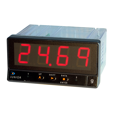
Device description ............................................................................................................................. 7
Dimensions and mounting .................................................................................................................. 7
Display and keyboard ........................................................................................................................ 8
Installing and connecting recommendations ........................................................................................ 8
Connections ...................................................................................................................................... 9
Wiring diagram for MAGNETIC sensor / SWITCH CONTACT input signal ............................................. 9
Wiring diagram for NAMUR sensor input signal ............................................................................... 10
Wiring diagram for NPN, PNP and TTL sensors or 24V DC ENCODER ............................................... 10
High voltage input signal wiring diagram ........................................................................................ 10
Remote counter RESET function wiring diagram ............................................................................. 10
Relays output ............................................................................................................................... 11
INPUT CONFIGURATION
Configuration menu.......................................................................................................................... 12
Input configuration .......................................................................................................................... 12
DISPLAY CONFIGURATION
Display programming ....................................................................................................................... 14
Counter mode (#1) ...................................................................................................................... 14
Tachometer rpm mode (#2) .......................................................................................................... 15
Tachometer rate mode (#3) .......................................................................................................... 15
Average measurement maximum time (tMAH) and time limit (tLiM) (tachometer mode only) ............ 16
SETPOINTS CONFIGURATION
Setpoints configuration .................................................................................................................... 17
Counter mode ('Cont') ................................................................................................................... 17
Tachometer mode ('tACH' y 'rAtE') ................................................................................................. 18
AVAILABLE KEYBOARD FUNCTIONS
TOTALIZER, MAX/MIN and RESET functions ...................................................................................... 19
Counter mode ('Cont') ................................................................................................................... 19
Tachometer mode ('tACH' y 'rAtE') ................................................................................................. 19
Direct access to Setpoints value ....................................................................................................... 20
Return to default configuration ......................................................................................................... 20
Access to lock-out configuration menu .............................................................................................. 20
CONFIGURATION LOCK-OUT
Lock-out menu ................................................................................................................................ 21
OUTPUT OPTION
Description ..................................................................................................................................... 23
Function modes description .............................................................................................................. 23
HI/LO mode activation .................................................................................................................. 23
Time delay (tachometer mode 'tACH' and 'rAtE' only) ..................................................................... 23
Asymmetrical hysteresis (tachometer mode 'tACH' and 'rAtE' only) .................................................. 23
1, 2, 3 and 4 control modes (for counter mode 'Cont' and Setpoint 2 only) ...................................... 24
Pulse output "PuLS" (for counter mode 'Cont' only) ........................................................................ 24
Latched output "LAtC" (for counter mode 'Cont' only) ..................................................................... 24
