DLX ASAP-HUB User manual

//
//
© 2021 DLX ENTERPRISES LLC. // VERSION 1.02 PROUDLY MADE IN THE USA. // CAGE CODE: 7CFK2 // DUNS #: 079751064 // SBA 8(a) CERTIFIED
ENGLISH MANUAL

//
//
//
© 2021 DLX ENTERPRISES LLC. // VERSION 1.02
//
TITLE HERE TITLE HERE
1 1
// LIMITED WARRANTY //
At Deployed Logix we’re redefining rapid deployment. Through our extensive
work with law enforcement, search and rescue teams, various first responders,
private organizations both domestically and abroad, and the military, our team
understands that when a crisis calls, seconds count. Discover why we are the
leader in American-made, rapidly deployable disaster preparedness products.
Your Deployed Logix handmade quality products are covered by a three-year
limited warranty. The limited warranty does not cover small imperfections due,
in part, to the production of handmade products. Any imperfections must be
limited and not inhibit the performance of the product. The limited warranty
is restricted to the repair or replacement of any part which proves to be
defective, at the discretion of Deployed Logix, and the claim must be made
in writing prior to the warranty’s expiration date. Deployed Logix will repair or
replace any component deemed to be faulty from manufacturing in the most
efficient and timely means available.
The limited warranty on workmanship is limited to defects at the time
of manufacturing and does not cover general wear, tear, or misuse of the
product. The warranty does not cover damage caused by abuse, misuse,
neglect, or improper care by the end user in the application of the Deployed
Logix product.
The products and/or components not manufactured by Deployed Logix
shall be subject only to the warranty extended by the original manufacturer.
Component manufacturer warranties may exceed that of Deployed Logix. No
warranty is made or implied regarding the intended use of the product.
Deployed Logix must authorize all claims prior to any action taken by the
end user. No items shall be returned for warranty repair without prior written
authorization from Deployed Logix. For replacement of products damaged
from general use and time please contact Deployed Logix in reference to the
“Buy Back Program.”
For immediate attention regarding any defective product, please phone
Customer Support at +1-541-357-5978, 8:00 AM – 5:00 PM, USA Pacific Time.
*This warranty does not cover marks, scuffs, or abrasions that might allow
light to pass through the blackout vinyl.
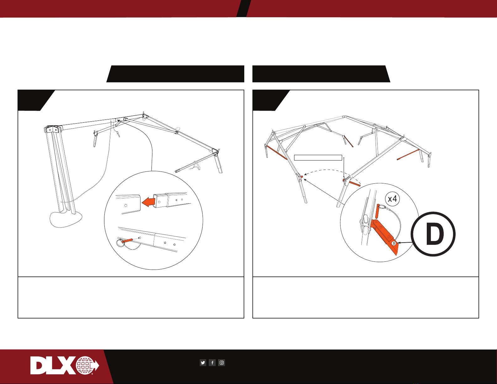
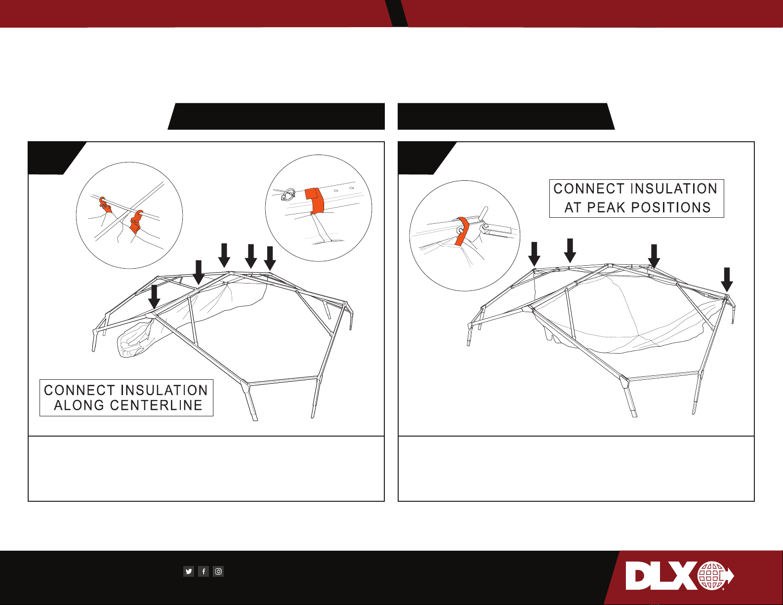
ASAP-HUB®
1
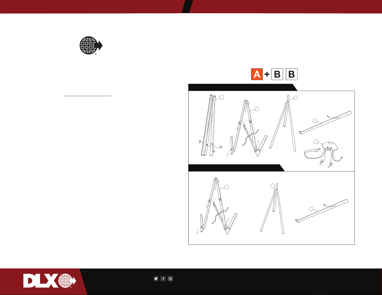
ASAP-HUB®SHELTER ARCH COMPONENTS
ASAP-HUB®CENTER & SUPPORT COMPONENTS
RIDGE SUPPORT
BAR
A
B
x4
x1
x2
®
ASAP-HUB
CENTER SUPPORT
ASSEMBLY
ARCH
ASSEMBLY
x2
RIDGE SUPPORT
BAR
FOOT PLATE
x4
SHELTER LEG
x4
SHELTER LEG
x2 x2
ARCH
ASSEMBLY

//
//
//
//
© 2021 DLX ENTERPRISES LLC. // VERSION 1.02 2
CENTER
DRAIN INSTALLATION DRAIN PUMP INSTALLATION
ROOF INSTALLATION SPRAYER ADJUSTMENT
ARCH SECTION SETUP ARCH SECTION SETUP
1 2
Retrieve arch sections from labeled frame bags. Swing joints and pin
in place. Be sure to orient pins toward interior of shelter to prevent
pin extraction.
Retrieve ridge support bars from labeled frame bags. Insert into
socket with label A facing up. Pin in place. Connect arms along
frame making sure angle points to center. Label B should align with
each other.

//
//
//
© 2021 DLX ENTERPRISES LLC. // VERSION 1.02
//
3
LABEL UP!
BOLT SHOULD FACE DOWN
DRAIN INSTALLATION DRAIN PUMP INSTALLATION
SPRAYER ADJUSTMENT
CENTER FRAME SETUP SHOULDER SUPPORT BARS
3 4
Position center frame section in desired location. Lift and connect
arch sections in a clockwise or counterclockwise rotation. Pin in
place with cable underneath frame.
Connect shoulder support bars. Orient support bar so that the Label
D faces up. Insert pin down into socket to secure.

//
//
//
//
© 2021 DLX ENTERPRISES LLC. // VERSION 1.02 4
DRAIN INSTALLATION DRAIN PUMP INSTALLATION
ROOF INSTALLATION SPRAYER ADJUSTMENT
INSULATION INSTALLATION INSULATION INSTALLATION
5 6
IF NOT UTILIZING INSULATION, SKIP TO STEP 8.
Locate centerline of insulation liner, connect snap clips to center
point on cables, then attach loops along centerline frame.
Connect insulation liner along opposite ridge line.

//
//
//
© 2021 DLX ENTERPRISES LLC. // VERSION 1.02
//
5
x8
DRAIN INSTALLATION DRAIN PUMP INSTALLATION
INSULATION INSTALLATION ROOF COVER INSTALLATION
7 8
Connect insulation liner around remaining perimeter of shelter
framework. Each quadrant of the shelter will have a minimum of four
(4) attachment points (BLACK ARROWS) for a total of sixteen (16)
perimeter attachment points.
Retrieve roof cover. Unfold starting at one side. Unroll to opposite
side. Place grommet onto post. Connect pins at provided locations
with open end facing out.

//
//
//
//
© 2021 DLX ENTERPRISES LLC. // VERSION 1.02 6
!
!
LIFT TWO ADJACENT CORNERS
SIMULTANEOUSLY TO MINIMIZE
STRESS ON FRAME JOINTS
2 PERSON MIN. 3 PERSON OPTIMUM
BEGIN AT PEAK
DRAIN INSTALLATION DRAIN PUMP INSTALLATION
ROOF INSTALLATION SPRAYER ADJUSTMENT
ENDWALL ATTACHMENT LEG ATTACHMENT
910
Attach endwalls. Begin attachment at peak of shelter and work
outward from center connecting hook and loop strips.
NOTE: Endwalls can be attached once shelter is fully erected.
Lift shelter one half first. Using four (4) personnel, lift at two corners
and attach two (2) legs per corner. Once first half is erected, repeat
step on opposite half.

//
//
//
© 2021 DLX ENTERPRISES LLC. // VERSION 1.02
//
7
CONNECT LANYARD
DRAIN INSTALLATION DRAIN PUMP INSTALLATION
FOOT ATTACHMENT ENDWALL / INSULATION ATTACHMENT
11 12
Connect shelter footpads. Align posts with socket on leg segments,
secure using pins with open end facing inward. Connect lanyards
around 4 base sides.
Complete connection of endwall hook and loop strips along vertical
portion of shelter. If insulation was utilized during setup, complete
attachment of loops to shelter frame segments at corner.

//
//
//
//
© 2021 DLX ENTERPRISES LLC. // VERSION 1.02 8
FOLD DOWN SKIRTS
CONNECT INTERIOR BUCKLES
POSITION FLOOR
UNDERNEATH FOOTPLATE
DRAIN INSTALLATION DRAIN PUMP INSTALLATION
FLOOR ATTACHMENT FOLD DOWN SKIRTS
13 14
Layout floor gray side up and position so the reinforced vinyl
segment aligns with each corner of the shelter frame. Fold up
floor and connect hook and loop strips on floor to matching strips
underneath endwall skirts.
Fold down skirts on endwalls and corner cover to deflect rain run-
off away from seams. Connect buckle on interior of shelter at each
corner.

//
//
//
© 2021 DLX ENTERPRISES LLC. // VERSION 1.02
//
9
~4 ft
DRAIN INSTALLATION DRAIN PUMP INSTALLATION
STAKING SHELTER STRIKE
! 1
SHELTER MUST BE STAKED & SECURED AT ALL TIMES WHEN
ERECTED. FAILURE TO SECURE STRUCTURE COULD RESULT IN
DAMAGE TO EQUIPMENT OR SERIOUS PERSONAL INJURY!
Begin strike of shelter by removing all installed accessories. Discon-
nect all power sources and climate control systems. Start by remov-
ing and folding endwalls. Folding instructions are provided at Step
10.

//
//
//
//
© 2021 DLX ENTERPRISES LLC. // VERSION 1.02 10
DRAIN INSTALLATION DRAIN PUMP INSTALLATION
INSULATION STRIKE INSULATION FOLDING
2 3
If insulation was used, begin takedown by rolling up all doors. If
additional shelters were connected, reattach insulation endwalls at
connected locations.
Disconnect insulation at all attachment points on the legs of the
shelter. Position yourself so you are on the interior of the shelter,
grip the hanging portion of the insulation and fold corners inwards.

//
//
//
© 2021 DLX ENTERPRISES LLC. // VERSION 1.02
//
11
!
!
LOWER TWO (2) ADJACENT SIDES
SIMULTANEOUSLY TO MINIMIZE
STRESS ON FRAME JOINTS
2 PERSON MIN. 3 OPTIMAL
CAUTION!
REMOVE LEGS &
LOWER SHELTER
DRAIN INSTALLATION DRAIN PUMP INSTALLATION
INSULATION REMOVAL SHELTER STRIKE
4 5
Once corners have been folded inwards, roll up and tie off with
provided straps.
REPEAT STEP 3 & 4 FOR EACH CORNER SEGMENT!
Lower shelter in halves, one side at a time. Using four (4) personnel,
lift two (2) corners and remove both sets of legs. Lower shelter to
ground. Proceed to opposite half and repeat process.

//
//
//
//
© 2021 DLX ENTERPRISES LLC. // VERSION 1.02 12
DRAIN INSTALLATION DRAIN PUMP INSTALLATION
FOLD ROOF COVER INSULATION REMOVAL
6 7
Remove each pin, and slide grommet off frame posts. Starting at one
side, fold roof over itself in 18 - 24” folds. Remove from frame and
fold to fit case or bag. Folding instructions are provided at Step 12.
Disconnect insulation straps from corner joints (BLACK ARROWS).
Disconnect insulation straps from arch sections (WHITE ARROWS).
DO NOT DISCONNECT STRAPS AT PEAK OR INTERIOR RIDGE-
LINES.

//
//
//
© 2021 DLX ENTERPRISES LLC. // VERSION 1.02
//
13
FOLD INSULATION
8
Disconnect insulation straps from one interior ridgeline (BLACK ARROWS).Pull insulation underneath itself to create half fold with ridgeline
still attached. Disconnect final interior ridgeline (WHITE ARROWS) and fold insulation. Folding instructions are provided on page 16.

//
//
//
//
© 2021 DLX ENTERPRISES LLC. // VERSION 1.02 14
HARD CASE NOTE: CENTER SECTION, x4
FEET AND STAKES CAN BE PLACED LOOSE
WITHIN CASE.
VINYL WRAP NOTE: IF TRANSPORTING IN
WRAP, DIVIDE FEET, STAKES AND CENTER
SECTION BETWEEN TWO FRAME BAGS.
DISASSEMBLE FRAME & PACK
FOR REDEPLOYMENT
DRAIN INSTALLATION DRAIN PUMP INSTALLATION
DISASSEMBLE FRAME PACK FRAME
! !
Disassemble shelter frame in reverse order from set up. Inspect
segments for dirty, broken or missing pieces. Perform any necessary
cleaning, repairs or replacement before repacking frame for
redeployment.
Lay out arch segment and nest two (2) legs on each side. Place sec-
ond arch section on top. Arrange support bars along top. Secure and
tighten straps. Repeat for remaining arch sections.

//
//
//
© 2021 DLX ENTERPRISES LLC. // VERSION 1.02
//
15
DRAIN INSTALLATION DRAIN PUMP INSTALLATION
FOLD ENDWALL FOLD ROOF
! ! EXTERIOR FACING UPEXTERIOR FACING UP

//
//
//
//
© 2021 DLX ENTERPRISES LLC. // VERSION 1.02 16
DRAIN INSTALLATION DRAIN PUMP INSTALLATION
FOLD FLOOR FOLD INSULATION
! !
INTERIOR FACING UP INTERIOR FACING UP

//
//
//
© 2021 DLX ENTERPRISES LLC. // VERSION 1.02
//
17
Turn the material over so that the adhesive side of the tab is facing up.
Position reinforcement filament tightly against the outside edge. The filament
should be perpendicular to the open end of the tear to create a tough solid
edge.
Fold over the patch’s 1 inch tab and rub to adhere to the back side of the
material.
Apply another patch to the back side of the patched tear (so that both sides of
material are patched). Rub the entire patch aggressively.
4.
5.
6.
7.
Tear on Edge
Fold 1 inch Tab Over Filament
Apply Leaving1inch Tab Beyond Edge ApplyReinforcement Filament
Apply to Back Side Cut Filament to Width of Patch
NOTE: Heating is an option and normally not needed unless temperatures are below freezing.
1.
2.
3.
Cut patch 1 inch beyond all edges of the tear. If using more than one patch,
overlap at least 1 inch. Trim and round corners.
Peel back 1/2 inch of paper liner.
Position exposed edge - allowing the patch to extend 1 inch beyond all edges
of the tear. Peel back the liner while applying the patch over tear. Follow
steps 1-3 on the back side of the repair if you have access to the back side.
Follow steps 1-3 with the following adjustments:
• Cut the patch size to extend a full 1 inch beyond the edge of the torn material.
• Peel and stick, positioning the patch with a 1 inch tab beyond the outside edge
of the torn material.
// REPAIRING GENERAL TEARS AND HOLES //
// REPAIRING TEARS EXTENDING THROUGH AN OUTSIDE EDGE //
DRAIN INSTALLATION DRAIN PUMP INSTALLATION
TEAR-AID APPLICATION TEAR-AID APPLICATION
! !

18
Table of contents
Other DLX Shelter manuals
Popular Shelter manuals by other brands

No Butts Bin
No Butts Bin SR1554 Assembly instructions

Storage Canopy
Storage Canopy 40x60x15 ST Container shelter Assembly manual

Crivit
Crivit 104155 Operation and safety notes

Coleman
Coleman 2000015507 Setup instructions

No Butts Bin
No Butts Bin SR1605-F Assembly instructions

Sojag
Sojag Octogonal Sunshelter 12x15 Assembly manual

Clam
Clam Dave Ctenz X4 TC 9201 manual

Kiwi Camping
Kiwi Camping SAVANNA POD KC074-413 Pitching instructions

Sunjoy
Sunjoy L-GZ512PST-C owner's manual

Jimmy at work
Jimmy at work SPR10012 instruction manual

Storage Canopy
Storage Canopy C3340 Assembly manual

Kiwi Camping
Kiwi Camping Savanna 4 Ezi-Up Pitching instructions