DMC TSC-25/RSA Series User manual

Analog Resistive Touch Screen Controller
TSC-25/RSA Series User’s Guide

1 Rev.1.3 ©2005-2006 DMC Co., Ltd.
TSC-25/RSA Series User’s Guide
Table of Contents
1. Product Overview....................................................................................................................2
1-1. Products Applicable ...........................................................................................................................2
1-2. Product Names ..................................................................................................................................2
1-3. Overview............................................................................................................................................2
2. Specifications..........................................................................................................................3
3. Connector.................................................................................................................................4
3-1. Explanation of a connector terminal...................................................................................................4
3-2. The mounted connector .....................................................................................................................4
4. Operation modes and functions............................................................................................ 5
4-1. Outline................................................................................................................................................5
4-2. Initialization mode and idle mode.......................................................................................................7
4-3. Coordinate data mode........................................................................................................................9
4-4. Calibration data setup mode ............................................................................................................12
4-5. Calibration data read mode..............................................................................................................16
4-6. Calibration data mode......................................................................................................................17
4-7. STOP mode .....................................................................................................................................20
4-8. Panel ID/mode information acquisition.............................................................................................21
4-9. Mode list...........................................................................................................................................22
4-10. Command list.................................................................................................................................22
5. Changes & Improvements....................................................................................................23
5-1. Version History.................................................................................................................................23
6. Warranty.................................................................................................................................24
6-1. Warranty Period ...............................................................................................................................24
6-2. Warranty Target ...............................................................................................................................24
6-3. Warranty Exceptions........................................................................................................................24
7. Precautions for Use ..............................................................................................................25
7-1. General Handling.............................................................................................................................25
7-2. Others ..............................................................................................................................................25
Dimensional Drawing

2 Rev.1.3 ©2005-2006 DMC Co., Ltd.
TSC-25/RSA Series User’s Guide
1. Product Overview
1-1. Products Applicable
This specification is applicable to TSC-25/RSA and TSC-25/RSA-E.
1-2. Product Names
Product Name Description
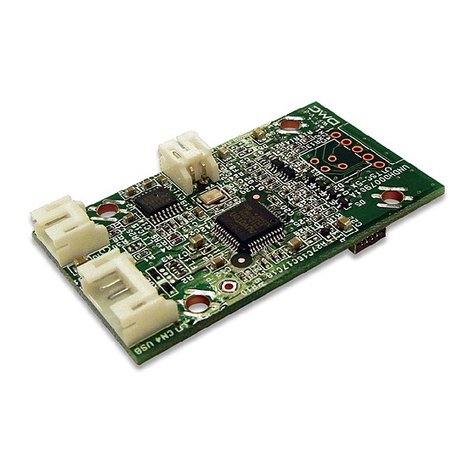
TSC-25/RSA TSC-20/IC installed touch screen controller board.
TSC-25/RSA-E TSC-20/IC installed touch screen controller board with EEPROM.
1-3. Overview
TSC-25/RSA and TSC-25/RSA-E are a touch screen controller board that performs an A/D conversion of
an analog signal of a 5 wire resistive touch screen, and transmits the coordinate data to the host in a 10-bit
resolution serial correspondence at 9600bps. TSC-25/RSA and TSC-25/RSA-E can be used for various
applications for its functions including the power saving mode, seven sampling speed settings (max.
150p/s *1), two external switch connections, and automatic calibration data loading with an external
EEPROM.
§ TSC-25/RSA TSC-25/RSA dispenses a need to newly design the peripheral circuits, and can easily
be used by connecting to the touch screen and the host. Using the driver software *2
enables the mouse emulation on various operation systems and dispenses the need
to newly design the controller software.
§ TSC-25/RSA-E An EEPROM installed version of TSC-25/RSA. The calibration data can be stored in
the EEPROM and automatically read after power-on.
*1: 150 transmissions of coordinate data per second.
*2: Please contact the local sales representatives for software availability.

3 Rev.1.3 ©2005-2006 DMC Co., Ltd.
TSC-25/RSA Series User’s Guide
2. Specifications
General Specifications
Item Rating Remarks
TSC-25/RSA
Operating Temp. TSC-25/RSA-E -20°C to +75°C
(No dew condensation)
TSC-25/RSA
Storing Temp. TSC-25/RSA-E -20°C to +85°C
(No dew condensation)
TSC-25/RSA
Supply Voltage TSC-25/RSA-E DC 4.1V to 5.5V
TSC-25/RSA
Supply Current TSC-25/RSA-E 40mA Vin=5.0V, At sampling Rate = 50p/s
when touch screen is activated
Format Asynchronous Serial
Transfer Rate 9600bps
Data Format 8bit
Stop Bit 1bit
Correspondence
Parity None
Fixed value
Frequency 6MHz 6MHz fixed
TSC-25/RSA
Dimension TSC-25/RSA-E 30 x 40 mm
5.5mm
Max height of components (2mm) When EEPROM mounted.
The backside of a board.
Performance Specifications
Description Rating Note
Coordinate Output Rate (point/sec)
(1) point mode
(2) 30p/s (3) 50p/s
(4) 80p/s (5) 100p/s
(6) 130p/s (7) 150p/s
Default: 50pps with DMC original
driver software.
Coordinate Resolution 10bit (1024 x 1024) The value will be lower in the active
area of the touch screen
Linearity Error ±3 LSB
Input Response Time 23ms Maximum value at 50pps.
When using the coordinate data mode

4 Rev.1.3 ©2005-2006 DMC Co., Ltd.
TSC-25/RSA Series User’s Guide
3. Connector
3-1. Explanation of a connector terminal
CN Terminal Name Function
1 XL/UR Touch screen Input XL/UR (Open if CN2 is used)
2 XR/LR Touch screen Input XR/LR (Open if CN2 is used)
3 Sense Coordinates detection (Open if CN2 is used)
4 YU/UL Touch screen Input YU/UL (Open if CN2 is used)
CN1
5 YD/LL Touch screen Input YD/LL (Open if CN2 is used)
1 YD/LL Touch screen Input YD/LL (Open if CN1 is used)
2 YU/UL Touch screen Input YU/UL (Open if CN1 is used)
3 Sense Coordinates detection (Open if CN2 is used)
4 XR/LR Touch screen Input XR/LR (Open if CN1 is used)
CN2
5 XL/UR Touch screen Input XL/UR (Open if CN1 is used)
1 Dout RS-232C Data Output
2 Din RS-232C Data Input
CN3
3 GND RS-232C GND
1 Dout RS-232C Data Output
2 Din RS-232C Data Input
CN4
3 GND RS-232C GND
1 Vin Power Input
CN5 2 GND GND
Either CN1 or CN2 is mounted.
Either CN3 or CN4 is mounted.
3-2. The mounted connector
CN P/N Manufacturer
CN1 RE-H052SD-1110 J.S.T. Mfg Co., Ltd
CN3 S3B-PH-K-S J.S.T. Mfg Co., Ltd
CN5 S2B-PH-K-S J.S.T. Mfg Co., Ltd

5 Rev.1.3 ©2005-2006 DMC Co., Ltd.
TSC-25/RSA Series User’s Guide
4. Operation modes and functions
4-1. Outline
TSC-20/IC enters the Initialization mode immediately after it is turned on or reset. In this mode, no setting
is made and each mode shall be set. To transition to the available state, select the coordinate output rate
and coordinate output mode and set the operation mode.
§ Initialization mode
By either power supply ON or hardware reset/software reset, the internal initial setting is performed. In
the serial scheme, communication with host is available. In USB scheme, device recognition process
ends. In this mode, both serial and USB schemes receive a coordinate output rate command and tran-
sition to the idle mode.
After hardware reset, it takes 500ms to transition to the initialization mode.
In using the EEPROM, EEPROM data is read in this mode.
§ Idle mode
TSC-20/IC enters this operation waiting mode after the coordinate output rate setting command is re-
ceived. Transition to each mode takes place in this mode.
§ Coordinate data mode
In this mode, analog data obtained from touch screen is output as coordinate data with 10 bit resolution
without any calibration.
This mode starts in the “idle mode“ by receiving the coordinate data send start command, and returns
to “idle mode” again after receiving the coordinate data send end command. By receiving reset com-
mand, it transitions to the ”initialization mode“.
This mode is used when host driver implements the calibration function, and also when necessary data
is obtained in the calibration data setup mode.
§ Calibration data setup mode
In this mode, calibration data used in “calibration data mode“ is set. Transition to this mode takes place
when the setup mode start command is received in the idle mode. Select an appropriate calibration
point among:
- X=2, Y=2 (four point calibration)
- X=3, Y=3 (nine point calibration) and
- X=2, Y=2 (four point calibration) plus one center position (five point calibration)
When this mode ends, calibration data is entered to EEPROM.
§ Calibration data read mode
In this mode, setup data is read out from EEPROM if in using EEPROM, data set in the ”calibration
data setup mode“ is stored to EEPROM. It is used if setting data is to be confirmed. Transition to this
mode takes place and calibration data is output to the host if in the idle mode, calibration data read
command is received.
§ Calibration data mode
In this mode, individual difference and loss in the touch screen are corrected and coordinate value out-
put is performed. Using calibration data set in the ”calibration data setup mode“, touch screen input
point and indicator’s cursor display position can be matched.
In using this mode, the host driver needs no calibration function.
Using “calibration data setup mode“ setting value to set the coordinate data maximum value, maximum
value can be limited to 10bits or less.
This mode starts when in the idle mode, any ”calibration data send start command“ is received, and
returns to the idle mode when receiving the calibration data send end command. When receiving the
reset command, this mode transitions to the initialization mode.
6 Rev.1.3 ©2005-2006 DMC Co., Ltd.
TSC-25/RSA Series User’s Guide
§ STOP mode
This mode is enabled only in the serial communication. This mode starts when in the idle mode, STOP
mode start command is received. This mode stops ceramic vibrator’s vibration and enters the power
saving mode where the operation stops. By hardware reset, this mode transitions to the initialization
mode. By receiving [00h] (null command) from host, the power saving mode ends and transitions to the
idle mode.
§ Power-save mode
This mode is only enabled in the serial communication. If in the coordinate data mode transitioned from
[01h] or the calibration data mode transitioned from [0Ah], there are no inputs on the touch screen for
20 samplings, the ceramic vibrator stops its vibration and enters the power saving mode where no op-
erations are taken. By inputting the touch screen or receiving a command from host, power saving
mode is released and the transition to “coordinate data mode “ or ”calibration data mode“ takes place.

7 Rev.1.3 ©2005-2006 DMC Co., Ltd.
TSC-25/RSA Series User’s Guide
4-2. Initialization mode and idle mode
After the power up or hardware reset, internal initialization setting is performed (about 500ms) and the
transition to the initialization mode occurs, where waiting for the communication with host. In this mode, if
external EEPROM is used, EEPROM data is read.
In the initialization mode, use the coordinate output rate setting command to set the interval for sending a
coordinate. Where, touch screen connection state and EEPROM data are checked and in either normal or
abnormal case, data representing each state is output to the host. Thus, the initialization mode transitions
to the idle mode. Transition to each mode occurs from the idle mode. Once coordinate output rate is set
with transition to the idle mode, coordinate output rate setting may be available again.
If in either idle mode, coordinate data mode or calibration data mode, reset command is received, transi-
tion to the initialization mode occurs. Where, after receiving the reset command, internal processing takes
a time, be sure to issue subsequent commands after 6ms or more is elapsed.
§ Mode transition
*After application of power (hardware-reset), to tell a host computer having changed into the
state where TSC-20/IC can communicate, it outputs “12h”. But, “12h” is not outputted when
software-reset is carried out.
§ Coordinate output rate setting command (S_Rate)
Mode Sampling Command Description
30p/s 05h+40h
50p/s 05h+41h
80p/s 05h+42h
100p/s 05h+43h
130p/s 05h+44h
Stream
150p/s 05h+45h
Point Once when
touched 05h+50h In the coordinate (calibration) data mode, no pen-up data
is output.
Host
TSC-20/IC
Initialization
(About 500ms)
Idle mode
Initialization mode
Internal initial setting
[S_Rate] [06h/15h]
[12h]
Power-on

8 Rev.1.3 ©2005-2006 DMC Co., Ltd.
TSC-25/RSA Series User’s Guide
§ Response command (no EEPROM is used)
State Response command Byte
width Description of mode
Normal 06h (ACK) 1 byte Touch screen connection normal
Abnormal 15h (NAK) 1 byte Touch screen not connected
§ Response command (EEPROM is used)
State Response command Byte
width Description of mode
Normal 06h (ACK) 1 byte Touch screen connection, EEPROM data
normal
15h (NAK) + detail code
bit0=1 (01h) EEPROM data empty
bit1=1 (02h) EEPROM data abnormal
bit2=1 (04h) EEPROM write error
Abnormal
bit3=1 (08h)
2 bytes
Touch screen not connected
* If, in the initialization mode, coordinate output rate setting is performed, EEPROM is checked if data is
present or not. Thus, error code only refers to EEPROM data empty (detail code: 01h).
In the idle mode, run the calibration data setup mode. After EEPROM data abnormal or EEPROM write
error occurs, set the coordinate output rate, error code is output, indicating EEPROM data abnormal or
EEPROM write error. Error flag can be deleted by either hardware reset or software reset.

9 Rev.1.3 ©2005-2006 DMC Co., Ltd.
TSC-25/RSA Series User’s Guide
4-3. Coordinate data mode
Analog data input from analog touch screen is A/D converted for calculating the coordinate data, which is
output in this mode.
This mode is used if calibration is made in the host driver. In using the external EEPROM in the calibration
data mode, previously performed ”calibration data setup mode“ needs raw data, which is obtained in this
mode.
From the idle mode, this mode starts by receiving either command of coordinate data send start 1 – 3, and
returns to the idle mode by receiving the coordinate data send end command. By receiving “reset” com-
mand, the mode transition to the initialization mode.
At the touch screen input (when a finger or pen touches on the touch screen), coordinate data, including
pen-down ID indicating that touch screen is input, is output to the host with coordinate output rate interval.
If the touch screen input ends (when a finger or pen leaves the touch screen), pen-up ID of 1byte is output
(excluding the point mode).
§ Mode transition
§ Command and each mode function
Mode name Command Function
Coordinate data send
start 1 01h
Pen-down: Coordinate data including pen-down ID is output with the
coordinate output rate interval.
Pen-up: Pen-up ID is output one time.
No input: If there are no inputs for 20 sampling times, transition to the
power-save mode occurs.
Coordinate data send
start 2 21h
Pen-down: Coordinate data including pen-down ID is output with the
coordinate output rate interval.
Pen-up: Coordinate data including pen-up ID is output with the co-
ordinate output rate interval.
No input: No transition to the power-save mode.
Coordinate data send
start 3 31h
Pen-down: Coordinate data including pen-down ID is output with the
coordinate output rate interval.
Pen-up: Pen-up ID is output one time.
No input: No transition to the power-save mode.
Coordinate data send
end 02h Coordinate data mode ends and transition to the idle mode occurs.
[02h]
Host
TSC-20/IC
Coordinate data mode
Idle mode
[01h/21h/31h] Coordinate
data
[06h]

10 Rev.1.3 ©2005-2006 DMC Co., Ltd.
TSC-25/RSA Series User’s Guide
§ Coordinate format
Pen-down data
Meaning b7 b6 b5 b4 b3 b2 b1 b0
Byte 0 Pen Down ID SW0 SW1 0 1 0 0 0 1
Byte 1 X Upper 0 0 0 0 0 0 X9 X8
Byte 2 X Lower X7 X6 X5 X4 X3 X2 X1 X0
Byte 3 Y Upper 0 0 0 0 0 0 Y9 Y8
Byte 4 Y Lower Y7 Y6 Y5 Y4 Y3 Y2 Y1 Y0
Pen-up data
Meaning b7 b6 b5 b4 b3 b2 b1 b0
Byte 0 Pen Up ID SW0 SW1 0 1 0 0 0 0
List of Pen-down ID (pen-down data Byte 0) List of pen-up ID (pen-up data Byte 0)
ID SW0 SW1 ID SW0 SW1
11h 0 0 10h 0 0
51h 0 1 50h 0 1
91h 1 0 90h 1 0
D1h 1 1 D0h 1 1
§ Example of Data (transmission starts at receiving [01h] or [31h]) (Where X = 0374h and Y = 01A9h)
Immediately after Pen-up, if the first sampling is pen-up, immediately preceding pen-down data is output. If
second time sampling is pen-up, none is output. If third time sampling is pen-up, pen-up data is output
once.
t
PD Data PD Data PD Data
Input OFF Input ON
X Upper X Lower Y Upper Y Lower
Bit 7 6 5 4 3 2 1 0
Data
1 0 1 0 1 0 0 1
Bit 7 6 5 4 3 2 1 0
Data
0 0 0 0 0 0 0 1
01h A9h
PD Data
PD ID
PU Data

11 Rev.1.3 ©2005-2006 DMC Co., Ltd.
TSC-25/RSA Series User’s Guide
§ Example of data (transmission starts at receiving [21h])
*: Immediately after Pen-up, if the first sampling is pen-up, immediately preceding pen-down data is output.
If second time sampling is pen-up, none is output. If third time sampling is pen-up, pen-up data is output.
Thereafter, pen-up data is output at the coordinate output rate interval. Coordinate value at pen-up always
takes same coordinate value as the last pen-down data. After the coordinate data mode transition until the
first pen-down, 0000h is output.
§ Power-save mode
“Coordinate data send start 1” command (01h) activates the transition to the coordinate data mode. If for
20 sampling times (Example: 100p/s = 200ms), no touch screen is input, ceramic vibrator’s vibration stops
and the operation ends by entering the power saving mode. Input to the touch screen (analog data input)
or command reception from host will release this mode, and after the vibration stabilization time elapses
(6ms), the operation returns to the coordinate data mode.
If TSC-20/IC receives ”coordinate data mode end” command (02h), this mode shall be released. Thus,
within 20 sampling times in the condition where either command (or touch screen input) releases this
mode, [02h] shall be received.
PU Data
t
PU Data PU Data PD Data PD Data PD Data PD Data PU Data
Input ON Input OFF
[06h]
Host
TSC-20
/
IC
Idle mode
Coordinate data mode
Power save mode
[02h]
Coordinate data
20 samplings
[Command]
Vibration
stabilization time
(6ms) 20 samplings

12 Rev.1.3 ©2005-2006 DMC Co., Ltd.
TSC-25/RSA Series User’s Guide
4-4. Calibration data setup mode
On the touch screen, due to offset and rotation
caused by shifted pasting on touch screen and ele-
ments such as losses from surrounding circuit, touch
screen input point and indicator coordinate indication
may be unmatched with each other if A/D conver-
sion value is output as coordinate value.
To resolve this, TSC-20/IC defines in advance any
point on touch screen as a calibration point, where
the calibration point’s raw coordinate (A/D conver-
sion value) and calibration coordinate value to be
output to the host after calibration, and in the actual
operation, from defined coordinate value, corre-
sponding calibration coordinate value of touch
screen input point’s raw coordinate is calculated and output to the host (calibration data mode).
In this mode, data required for calibration is set up. Number of maximum calibration points is nine in total
with X = 3 and Y = 3.
For setup in this mode, coordinates of calibration points in the coordinate data mode shall be obtained in
advance.
By receiving setup mode start command in the idle mode, the operation transitions to this mode and after
setup processing ends, data corresponding to the normal end or abnormal end is output to the host, then
the operation returns to the idle mode.
If the external EEPROM is used, this processing writes data to EEPROM.
§ Mode transition
*Within 300 msec after the last data (calibration data maximum value) is received and until the operation
transitions to the idle mode, no command reception is available.
§ Command
Mode Command Function
Setup mode start 1 0Dh Normal calibration (Specify the number of calibration
points in X and Y each)
Setup mode start 2 0Eh Five point calibration (four points at touch screen’s 4 cor-
ners and one point at the center)
Maximum
value
Host
TSC-20/IC
Coordination data setup
Idle mode
[0Dh/0Eh] Coordinate
data [06h/15h]
Number o
f
points
300ms
T
ouc
h
screen
LCD
di
sp
l
a
y
area
C
orrec
ti
on po
i
n
t
X
coor
di
na
t
e
Y
coor
di
na
t
e
D
e
fi
ne coor
di
na
t
e
values
corresponding to
correction points

13 Rev.1.3 ©2005-2006 DMC Co., Ltd.
TSC-25/RSA Series User’s Guide
§ Response command (no EEPROM is used)
State Response command Bit
width Mode description
Normal 06h (ACK) 1 byte Setting completed
Abnormal 15h (NAK) 1 byte Parameter abnormal
§ Response command (EEPROM is used)
State Response command Bit
width Mode description
Normal 06h (ACK) 1 byte EEPROM write normal
15h (NAK) + detail code
bit1=1 (02h) EEPROM data abnormal
Abnormal bit2=1 (04h) 2 bytes EEPROM write error

14 Rev.1.3 ©2005-2006 DMC Co., Ltd.
TSC-25/RSA Series User’s Guide
§ Setup procedure
1. Define calibration point and number of calibration points and display a cross mark and arrow on
indicator to obtain coordinate values at the calibration point in the coordinate data mode.
2. Transmit command [0Dh/0Eh] to TSC-20/IC (transition to ”calibration data setup mode“), and in-
put data according to the calibration data setting format. After all data are input, ACK/NAK is out-
put to the host and the operation automatically transitions to the idle mode.
§ Calibration data setting format
1. Number of points: X direction = 3, Y direction = 3 (Maximum coordinate value: 0000h - 03FFh)
Idle mode
Coordinate data mode
Idle mode
Coordination data setup
Idle mode
Retrieve raw data of
correction points
Input raw data of correction
points, correction data and
maximum coordinate value
0Dh
03h
03h
P00 coordinate value
P01 coordinate value
P02 coordinate value
P10 coordinate value
P12 coordinate value
P22 coordinate value
X Maximum coordinate value
Y Maximum coordinate value
1 byte
8 byte
Y raw coordinate value
X raw coordinate value
X correction
coordinate value
Y correction
coordinate value
Upper layer
Lower layer
Upper layer
Lower layer
1 byte
1 byte
8 byte
8 byte
8 byte
8 byte
8 byte
2 byte
2 byte
2 byte
2 byte
2 byte
2 byte
1 byte
1 byte
1 byte
1 byte
Correction point (origin at top left)
P00 P01 P02
P10 P11 P12
P20 P21 P22

15 Rev.1.3 ©2005-2006 DMC Co., Ltd.
TSC-25/RSA Series User’s Guide
2. Number of points: X = 2, Y = 2 and 5 point
§ Handling outside the coordinate range
If a portion only of the touch screen is to be operated, some calibration may cause the touch screen
input points even inside the input area to be located outside the maximum coordinate point (or mini-
mum coordinate point). Where, touch screen input is not disabled and the following data is transmitted.
0Dh
02h
02h
P00 Coordinate value
P01 Coordinate value
P10 Coordinate value
P11 Coordinate value
X Maximum coordinate
value
Y Maximum coordinate
value
1 byte
8 byte
03h
FFh
1 byte
1 byte
8 byte
8 byte
8 byte
2 byte
2 byte
1 byte
1 byte
Correction point (origin: top left)
0Eh
P00 Coordinate value
P01 Coordinate value
P10 Coordinate value
P11 Coordinate value
PCT Coordinate value
X Maximum coordinate
value
Y Maximum coordinate
1 byte
8 byte
03h
FFh
8 byte
8 byte
8 byte
8 byte
8 byte
2 byte
1 byte
1 byte
Correction point (origin: top left)
X=2, Y=2 (Maximum coordinate value: X=03FFh, Y=03FFh) 5 Point (Maximum coordinate value: X=03FFh, Y=03FFh)
P00 P01
P10 P11
P00 P01
P10 P11
* PCT is at the center of indicator.
PCT
Maximum coordinate value (X = 03 FF, Y= 03 FF)
Input area
X: 00 00
Y: 00 00
Minimum coordinate value (X = 00 00, Y= 00 00)
X: Coordinate
Y: 00 00 X: 03 FF
Y: 00 00
X: 00 00
Y: Coordinate
X: 00 00
Y: 03 FF X: Coordinate
Y: 03 FF X: 03 FF
Y: 03 FF
X: 03 FF
Y: Coordinate
Touch screen oute
r
frame

16 Rev.1.3 ©2005-2006 DMC Co., Ltd.
TSC-25/RSA Series User’s Guide
4-5. Calibration data read mode
In this mode, data set in the calibration data setup mode is read from EEPROM, used to check the pa-
rameter setting.
This mode is executed from idle mode to transmit the stored calibration data, then the operation automati-
cally transitions to idle mode. If no calibration data is stored in EEPROM, none is output.
Note) In this mode, number of calibration points is treated with 25 point (X=5, Y=5) format, since FIT-10/IC, a touch
screen controller IC, supports the maximum 25 point calibration function and protocol compatibility in the serial mode
shall be kept with FIT-10/IC. Coordinate data of calibration points not supported by TSC-20/IC are all output with 0000h.
§ Mode transition
§ Calibration data send format
In the idle mode, if 1Dh is received, calibration data is sent to the host with the following format.
In the calibration data setup mode, if setup mode start 2 (0Eh) is used, data is converted to nine point cali-
bration (X=3, Y=3) for setup mode start 1 (0Dh) then stored, thus if output to the host, it uses nine point
calibration format.
Maximum
Host
TSC-20/IC
Correction data read mode
Idle mode
[1Dh] Coordinate
data
Number o
f
points
X_P
Y_P
P00 coordinate value
P01 coordinate value
P02 coordinate value
P43 coordinate value
Y Maximum coordinate
value
P44 coordinate value
X Maximum coordinate
value
P00 P01 P02 P03 P0
4
P10 P11 P12 P13 P14
P20 P21 P22 P23 P24
P30 P31 P32 P33 P34
P40 P41 P42 P43 P44
Correction points (5
×
5)
1 byte
1 byte
8 byte
8 byte
8 byte
8 byte
8 byte
2 byte
2 byte
Y raw coordinate value
X raw coordinate value
X correction
coordinate value
Y correction
coordinate value
2 byte
2 byte
2 byte
2 byte
Upper layer
Lower layer
1 byte
1 byte
Upper layer
Lower layer
1 byte
1 byte

17 Rev.1.3 ©2005-2006 DMC Co., Ltd.
TSC-25/RSA Series User’s Guide
4-6. Calibration data mode
In this mode, based on calibration value obtained from the calibration data setup mode, coordinate value is
corrected and output. In this mode, maximum output coordinate value can be limited.
From the idle mode, this mode starts by receiving either command of coordinate data send start 1 – 3, and
returns to the idle mode by receiving the calibration data send end command. By receiving “reset” com-
mand, the mode transition to the initialization mode.
At the touch screen input (when a finger or pen touches on the touch screen), coordinate data, including
pen-down ID indicating that touch screen is input, is output to the host with coordinate output rate interval.
If the touch screen input ends (when a finger or pen leaves the touch screen), pen-up ID of 1byte is output
(excluding the point mode).
§ Mode transition
§ Command and mode function
Mode name Command Function
Calibration data send
start 1 0Ah
Pen-down: Coordinate data including pen-down ID is output with the
coordinate output rate interval.
Pen-up: Pen-up ID is output one time.
No input: If there are no inputs for 20 sampling times, transition to the
power-save mode occurs.
Calibration data send
start 2 2Ah
Pen-down: Coordinate data including pen-down ID is output with the
coordinate output rate interval.
Pen-up: Coordinate data including pen-up ID is output with the coor-
dinate output rate interval.
No input: No transition to the power-save mode.
Calibration data send
start 3 3Ah
Pen-down: Coordinate data including pen-down ID is output with the
coordinate output rate interval.
Pen-up: Pen-up ID is output one time.
No input: No transition to the power-save mode.
Calibration data send
end 0Bh Coordinate data mode ends and transition to the idle mode occurs.
[0Bh]
Host
TSC-20/IC
Correction data mode
Idle mode
[
0Ah/2Ah/3Ah
]
Coordinate
data [06h]

18 Rev.1.3 ©2005-2006 DMC Co., Ltd.
TSC-25/RSA Series User’s Guide
§ Power-save mode
“Coordinate data send start 1” command (0Ah) activates the transition to the coordinate data mode. If for
20 sampling times, no touch screen is input, ceramic vibrator’s vibration stops and the operation ends by
entering the power saving mode. Input to the touch screen (analog data input) or command reception from
host will release this mode, and after the vibration stabilization time elapses (6ms), the operation returns to
the calibration data mode.
If TSC-20/IC receives “calibration data mode end” command (0Bh), this mode shall be released. Thus,
within 20 sampling times in the condition where either command (or touch screen input) releases this
mode, [0Bh] shall be received.
Host
TSC-20/IC
Idle mode
Correction data mode
Power save mode
[0Bh]Coordinate data
20 samplings
[Command]
Vibration stabi
lization time
(6ms) 20 samplings
[06h]

19 Rev.1.3 ©2005-2006 DMC Co., Ltd.
TSC-25/RSA Series User’s Guide
t
PD Data PD Data PD Data
Input OFF Input ON
X Upper X Lower Y Upper Y Lower
Bit 7 6 5 4 3 2 1 0
Data
1 0 1 0 1 0 0 1
Bit 7 6 5 4 3 2 1 0
Data
0 0 0 0 0 0 0 1
01h A9h
PD Data
PD ID
PU Data
§ Data description
Pen-down data
Meaning b7 b6 b5 b4 b3 b2 b1 b0
Byte 0 Pen Down ID SW0 SW1 0 1 0 0 0 1
Byte 1 X Upper 0 0 0 0 0 0 X9 X8
Byte 2 X Lower X7 X6 X5 X4 X3 X2 X1 X0
Byte 3 Y Upper 0 0 0 0 0 0 Y9 Y8
Byte 4 Y Lower Y7 Y6 Y5 Y4 Y3 Y2 Y1 Y0
Pen-up data
Meaning b7 b6 b5 b4 b3 b2 b1 b0
Byte 0 Pen Up ID SW0 SW1 0 1 0 0 0 0
List of pen-down ID (pen-down data Byte 0) List of pen-up ID (pen-up data Byte 0)
ID SW0 SW1 ID SW0 SW1
11h 0 0 10h 0 0
51h 0 1 50h 0 1
91h 1 0 90h 1 0
D1h 1 1 D0h 1 1
§ Example of data (transmission starts by receiving [0Ah] or [3Ah]) (Where, X = 0374h and Y = 01A9h)
Immediately after Pen-up, if the first sampling is pen-up, immediately preceding pen-down data is output. If
second time sampling is pen-up, none is output. If third time sampling is pen-up, pen-up data is output
once.
This manual suits for next models
2
Table of contents
Other DMC Controllers manuals

DMC
DMC PSE445TM01 User manual

DMC
DMC TSC-30/IC Owner's manual

DMC
DMC Calc-U-Dri PRINTER User manual

DMC
DMC TSC-55/RU User manual

DMC
DMC TSC-35/RU User manual

DMC
DMC TSC-34/U-L User manual

DMC
DMC TSC-55/U-L User manual

DMC
DMC TSC-40/IC Installation instructions

DMC
DMC TSC-54/RU User manual

DMC
DMC 84 User manual
Popular Controllers manuals by other brands

Parker
Parker LCB Series Installation, Commissioning, Maintenance and Repair

Toho Electronics
Toho Electronics TTM-200 Series Operation Manual, Communications

Rachio
Rachio Generation 2 quick start guide

Omega
Omega CN16Pt user guide

LinMot
LinMot E1200-GP-UC Data Sheet & Installation Guide

ESBE
ESBE CR Series manual