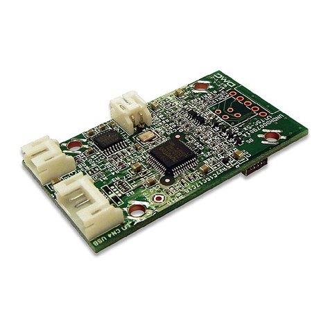
DMC 84 User manual

OWNER’S MANUAL
MODEL 84
GRAIN FLOW
Calc-U-Dri Controls
PNEG-1148
Date:9-21-06
PNEG-1148

2
Grain Flow The GSI Group, Inc. Warranty
THE GSI GROUP, INC. (“GSI”) WARRANTS ALL PRODUCTS WHICH IT MANUFACTURES TO
BE FREE OF DEFECTS IN MATERIAL AND WORKMANSHIP UNDER NORMAL USAGE AND
CONDITIONS FOR A PERIOD OF 12 MONTHS AFTER RETAIL SALE TO THE ORIGINAL END
USER. THE PURCHASER’S SOLE REMEDY AND GSI’S ONLY OBLIGATION SHALL BE TO
REPAIR OR REPLACE, AT GSI’S OPTION AND EXPENSE, PRODUCTS THAT, IN GSI’S SOLE
JUDGMENT, CONTAIN A MATERIAL DEFECT DUE TO MATERIALS OR WORKMANSHIP.
ALL DELIVERY AND SHIPMENT CHARGES TO AND FROM GSI’S FACTORY WILL BE
PURCHASER’S RESPONSIBILITY. EXPENSES INCURRED BY OR ON BEHALF OF THE
PURCHASER WITHOUT PRIOR WRITTEN AUTHORIZATION FROM AN AUTHORIZED
EMPLOYEE OF GSI SHALL BE THE SOLE RESPONSIBILITY OF THE PURCHASER.
EXCEPT FOR THE LIMITED WARRANTY EXPRESSED ABOVE, GSI MAKES NO FURTHER
WARRANTY OF ANY KIND, EXPRESS OR IMPLIED, INCLUDING, WITHOUT LIMITATION,
WARRANTIES OF MERCHANTABILITY OR FITNESS FOR A PARTICULAR PURPOSE OR
USE IN CONNECTION WITH (I) PRODUCT MANUFACTURED OR SOLD BY GSI OR (ii) ANY
ADVICE, INSTRUCTION, RECOMMENDATION OR SUGGESTION PROVIDED BY AN AGENT,
REPRESENTATIVE OR EMPLOYEE OF GSI REGARDING OR RELATED TO THE
CONFIGURATION, INSTALLATION, LAYOUT, SUITABILITY FOR A PARTICULAR PURPOSE,
OR DESIGN OF SUCH PRODUCTS.
GSI SHALL NOT BE LIABLE FOR ANY DIRECT, INDIRECT, INCIDENTAL OR
CONSEQUENTIAL DAMAGES, INCLUDING, WITHOUT LIMITATION, LOSS OF ANTICIPATED
PROFITS OR BENEFITS. PURCHASER’S SOLE AND EXCLUSIVE REMEDY IS AS SET FORTH
IN THE LIMITED WARRANTY EXPRESSED ABOVE, WHICH SHALL NOT EXCEED THE
AMOUNT PAID FOR THE PRODUCT PURCHASED. THIS WARRANTY IS NOT
TRANSFERABLE AND APPLIES ONLY TO THE ORIGINAL PURCHASER. GSI SHALL HAVE
NO OBLIGATION OR RESPONSIBILITY FOR ANY REPRESENTATIONS OR WARRANTIES
MADE BY OR ON BEHALF OF ANY DEALER, AGENT OR DISTRIBUTOR OF GSI.
GSI ASSUMES NO RESPONSIBILITY FOR CLAIMS RESULTING FROM ERECTION DEFECTS
OR UNAUTHORIZED MODIFICATIONS TO PRODUCTS WHICH IT MANUFACTURED.
MODIFICATIONS TO PRODUCTS NOT SPECIFICALLY DELINEATED IN THE MANUAL
ACCOMPANYING THE EQUIPMENT AT INITIAL SALE WILL NULLIFY THE PRODUCT
WARRANTY THAT MIGHT HAVE BEEN OTHERWISE AVAILABLE.
THE FOREGOING WARRANTY SHALL NOT EXTEND TO PRODUCTS OR PARTS WHICH
HAVE BEEN DAMAGED BY NEGLIGENT USE, MISUSE, ALTERATION OR ACCIDENT. THIS
WARRANTY EXTENDS SOLELY TO ONLY PRODUCTS MANUFACTURED BY GSI. THIS
WARRANTY IS EXCLUSIVE AND IN LIEU OF ALL OTHER WARRANTIES EXPRESS OR
IMPLIED. GSI RESERVES THE RIGHT TO MAKE DESIGN OR SPECIFICATION CHANGES AT
ANY TIME.
PRIOR TO INSTALLATION, PURCHASER HAS THE RESPONSIBILITY TO COMPLY WITH
ALL FEDERAL, STATE AND LOCAL CODES WHICH MAY APPLY TO THE LOCATION AND
INSTALLATION OF PRODUCTS MANUFACTURED OR SOLD BY GSI.
PHLEGAL: #1832020 v1 (139LG01!.DOC) (revised December 2005)

3
Grain Flow
TABLE OF CONTENTS
*IMPORTANT! Itis veryimportantforthe dealerand/or the person(s) installingthe Grain Flow
(withDry Grain Control for the Calc-U-Dri) togo throughthe Start-UpChecklistProcedure.
Failure to do so will invalidate warranty.
SAFETYGUIDELINES........................................................................................................... 4 - 8
DECALLOCATIONS .............................................................................................................9 - 11
Introduction ............................................................................................................................... 12
OverallDimensions-Grain Flow................................................................................................ 13
GrainFlow Installation Instructions......................................................................................14 -25
GrainSamplerInstallation ............................................................................................ 21
Straight Out SwivelBoot Installation ....................................................................................25 - 26
GimbalSwivelBoot Installation ...........................................................................................26 - 27
VerticalAugerInstallation ....................................................................................................28 - 30
VerticalAuger Optional Equipment ............................................................................................ 31
Take-AwayAuger ControlBox Installation ................................................................................. 31
InclinedAuger ........................................................................................................................... 31
MainControl Box Installation...............................................................................................32- 33
OperationsFlowChart................................................................................................................ 34
Start-UpChecklist ...............................................................................................................35 - 36
OperatingSuggestions........................................................................................................37 - 39
DryingGuideChart.................................................................................................................... 40
ControlFunctions.................................................................................................................41-43
FusesandThermal Unit Chart................................................................................................... 44
Parts List & Exploded Views
Control Box - 230V, 1 PH .......................................................................................46 - 47
Control Box - 230V, 3 PH .......................................................................................48 - 49
Control Box - 440V, 3 PH .......................................................................................50 - 51
ControlModule .......................................................................................................52 - 53
Discharge& Power Unit .........................................................................................54 - 55
Center Sump & Gear BoxAssembly ......................................................................56 - 57
Take-AwayAugerControl Box ................................................................................58 - 59
VerticalAuger.........................................................................................................60 - 61
VerticalAugerAccessories .....................................................................................62 - 63
OptionalEquipment................................................................................................64 - 65
Dual Center Gear Box (mfg. by Hub city)................................................................66 - 67
DualCenter Gear Gox (mfg. byCurtis) ...................................................................68 - 69
WiringDiagrams .................................................................................................................70 - 73
ElectricalHook-Ups ............................................................................................................74 - 80
AnnualStart-UpChecklist ......................................................................................................... 81
CircuitBoardRemoval............................................................................................................... 82
Stirring Equipment...............................................................................................................83 - 84
TroubleShooting .................................................................................................................85 - 87
Calc-U-DriSupplementforNECOandShivvers....................................................................88 - 93
AppendixA(Dip Switch Settings) .............................................................................................. 94
AppendixB(Sampling).............................................................................................................. 95
4
Grain Flow
Thismanual containsinformationthat isimportantfor you,the owner/operator,toknow and
understand.This informationrelatesto protecting personal safety andpreventing
equipment problems.It isthe responsibilityof theowner/operator toinform anyone
operatingor workinginthe areaof thisequipmentof thesesafety guidelines.Tohelpyou
recognizethis information,we usethesymbolsthatare definedbelow.
Pleaseread themanualand payattention tothesesections. Failureto readthis manual
andit’s safetyinstructionsis amisuse oftheequipment andmay leadtoserious injuryor death.
SAFETY GUIDELINES
DANGER indicatesan imminently hazardous situation which,if not
avoided,will resultin death or serious injury.
This is the safety alert symbol. It is used to alert you
to potential personal injury hazards. Obey all
safety messages that follow this symbol to avoid possible
injury or death.
WARNING indicates a potentially hazardous situation which, if not
avoided,could result in death or serious injury.
CAUTION indicatesa potentially hazardoussituation which,if not avoided,
may result in minor or moderate injury.
CAUTION used without the safety alert symbol indicates a potentially
hazardoussituation which, if not avoided, may resultin property
damage.
NOTE indicatesinformation about the equipment thatyou shouldpay
special attention to.

5
Grain Flow
FOLLOW SAFETY INSTRUCTIONS
Carefully read all safety messages in this manual
and on your machine safety signs. Keep signs in
good condition. Replace missing or damaged
safety signs. Be sure new equipment compo-
nents and repair parts include the current safety
signs. Replacement safety signs are available
from the manufacturer.
Learn how to operate the machine and how to
use controls properly. Do not let anyone operate
without instruction.
Keep your machinery in proper working condi-
tion. Unauthorized modifications to the machine
may impair the function and/or safety and affect
machine life.
If you do not understand any part of this manual
and need assistance, contact your dealer.
STAY CLEAR OF ROTATING PARTS
Entanglement in rotating augers will cause serious
injury or death. Be sure all people are clear of the
equipment before start-up.
Keep all shields and covers in place at all times.
Wear close fitting clothing. Stop and lock out power
source before making adjustments, cleaning, or
maintainingequipment.
NEVER ENTER BIN WITHOUT LOCKING OUTALL
POWER SOURCES! Floor augers travel around at a
rapid speed. AUTOMATIC CONTROLS START
AUGERS WITHOUT WARNING!!
If you must enter the bin:
1. Shut off and lock out all power.
2. Use a safety harness and safety line.
3. Station another person outside the bin.
4.Avoid the center of the bin.
5. Wear proper breathing equipment or respirator.
Failure to head these warnings will result in serious
injury or death.

6
Grain Flow
PRACTICE SAFE MAINTENANCE
Understand service procedures before doing
work. Keep area clean and dry.
Lock out all power sources before performing
any maintenance. Never lubricate, service, or
adjust machine while it is in operation. Keep
hands, feet, and clothing from rotating parts.
Keep all parts in good condition and properly
installed. Fix damage immediately. Replace
worn or broken parts. Remove any build up
grease, oil, or debris.
OPERATE MOTOR PROPERLY
Do not operate electric motor equipped units until motors
are properly grounded. GROUND all electrical equipment
as well as the BIN ITSELF.
Disconnect power on electrical driven units before servic-
ing or opening the control box, adjusting, or lubricating the
equipment.
All electrical hook-ups should be in accordance with all
Local and National Electical Codes.
An automatic shut-off of the Calc-U-Dri and burner for grain
depths less than two feet is recommended.
Do not repetitively stop and start the drive in order to free a
plugged condition. Jogging the drive in this type of condition
can damage the equipment and/or drive components.
STAY CLEAR OF HOISTED EQUIPMENT
Always use proper lifting/hoisting
equipment when assembling or
disassembling equipment.
Do not walk or stand under hoisted equipment.
Always use sturdy and stable supports when
neededfor installation.

7
Grain Flow
PREPARE FOR EMERGENCIES
Be prepared if fire starts.
Keep a first aid kit and fire extinguisher handy.
Keep emergency numbers for doctors, ambu-
lance service, hospital, and fire department near
yourtelephone.
WEAR PROTECTIVE CLOTHING
Wear close fitting clothing and safety equipment
appropriate to the job.
Safety glasses should be worn at all times to
protect eyes from debris.
Wear gloves to protect your hands from sharp
edges on plastic or steel parts.
A respirator may be needed to help prevent
breathing potentially toxic fumes and dust.
Wear hard hat and steel toe boots to help
protect your head and toes from falling debris.
Eye Protection
Gloves
Steel Toe
Boots
Respirator
Hard Hat

8
Grain Flow
OPERATORQUALIFICATIONS
A. The User/Operator mustbe competent andexperienced to operateauger equipment. Anyonewho works
withor aroundaugers must have good common sense in order to be qualified. These persons must also
know and meet all other qualifications, such as:
1. Anypersonwho has notread and/ordoes notunderstand all operation and safety
procedures is not qualified to operate any auger systems.
2. Certainregulationsapplytopersonnel operating powermachinery. Personnel under
the age of 18 years may not operate power machinery, including augers. It is your
responsibility, as ownerand/or supervisor, to know whatthese regulationsare in your
areaor situation.
3. Unqualifiedorincompetent persons are to remainout ofthe work area.The“WorkArea” isdefined as
any area within the grain drying and storage complex where this equipment is intalled.
4. O.S.H.A. (Occupational Safety & HealthAdministration) regulations state:
"At the time of initial assignment and at least annually thereafter, the employer shall
instructevery employee inthe safe operationand servicingof all equipmentwith
whichthe employeeis, orwill beinvolved." (Federal OccupationalSafety &Health
StandardsforAgriculture. SubpartD, Section 19287.57 (a) (6).
B. As a requirement of OSHA, it is necessary for the employer to train the employee in the safe operating
andsafety procedures for this auger. Weincludedthissign-offsheetfor yourconvenience and personal
record keeping. All unqualified persons are to stay out of the work area at all times. It is strongly recom-
mendedthat another qualifiedperson whoknows the shutdownprocedure isin the areain the event of an
emergency. Aperson who has not read this manual and understands all operating and safety instructions
is not qualified to operate the machine.
Date Employer's Signature Employee's Signature

9
Installation
PNEG-1148 Grain Flow
REPLACEMENTS ARE AVAILABLE UPON REQUEST
Write to: DMC
1004 East Illinois St.
Assumption, IL 62510
Phone: 217-226-4421
Please note:1. The decals on these pages are not actual size.
2. Keep all decals wiped clean at all times.
3. All decals must be replaced if they are destroyed, missing,
painted over, or can no longer be read.
DC-889
DC-889
Located inside control box.
DC-1728
Located inside on door of
control box.

10
Installation PNEG-1148 Grain Flow
THE DECALS SHOWN ON THESE PAGES MUST BE
DISPLAYED AS SHOWN
DC-GBC-1A(English)&
DC-GBC-1S(Spanish)
Decal on inside of doors
Rotating flighting will
kill or dismember. Flowing material will
trap and suffocate. Crusted material will
collapse and suffocate.
Keep clear of all augers.
DO NOT ENTER this bin!
Failure to heed these
warnings will result in
serious injury or death.
DC-GBC-1A
1. Shut off and lock out all power.
2. Use a safety harness and safety line.
3. Station another person outside the bin.
4. Avoid the center of the bin.
5. Wear proper breathing equipment or respirator.
If you must enter the bin:
2
356
4
1

11
Installation
PNEG-1148 Grain Flow
WARNING
SHEAR POINT
DC-995
Keep hands clear of moving
parts. Do not operate with
guard removed. Disconnect
and lockout power before
servicing.
SHEAR POINT
Keep hands clear of moving
parts. Do not operate with
guard removed. Disconnect
and lockout power before
servicing.
DC-994
NOTICE
Check oil level
in both
gearboxes
to installation.
PRIOR
SEE OWNER'S MANUAL
DC-1730
2
.
0
0
"
DC-1728
NOTICE
To avoid equipment damage:
Fully clean out augers.
DO NOT leave grain in the
discharge auger during
storage periods.
SEE OWNER'S MANUAL
DC-1731
NOTICE
FLOOR AUGER DRIVE.
SHUT OFF MAIN POWER SWITCH
TO ENGAGE OR TO DISENGAGE.
Do not remove or insert
board with the power on.
Failure to follow proper procedures
may result in damage to circuit board.
DC-1732
DC-1732
Located inside on door of control box. DC-1731
Located on outside of bin.
DC-994
Located next to belt drive. DC-995
Located on belt guard cover.
DC-1728
Located on outside of bin. DC-1730
Located on outside of bin.
12
34
56

12
Installation PNEG-1148 Grain Flow
INTRODUCTION
TheDMC GrainFlow turnsyour bininto themostaccurate,efficientandprofitablecontinu-
ousflow dryingsystemavailable.
Your newGrainFlowContinuousIn-bin Dry-Flowsystem isaqualitymachine,and with
propermaintenance, itwill serveyoufor yearsto come.
Beforeoperating, familiarizeyourself withthe machine. Itwill helpyou tooperate your
GrainFlow moreefficiently,resultinginbetterqualityreturns toyou.
Limitthe amount ofgrain abovetheGrain Flowto a maximumdepth of16feet.
Havingyour fanand heaterproperlysized andoperating correctlyis necessaryto getthe
capacities specified in the Drying Chart (shown on page 40).
Seeyour dealer forthe details ona completelineof availableoptionalequipment tomatch
yourdryingneeds.
PATENT NOTICE: The Calc-u-Dri Control Box is patent pending.

13
Installation
PNEG-1148 Grain Flow
Two-Way Valve Three-Way Valve Three-Way Valve Two-Way Valve Three-Way Valve
Upper Lower
“A” “A” “A” “B” “B”
Vertical Auger
15’ 10’1” 10’6” 10’2” 9’5” 9’2”
Vertical Auger
18’ 13’1” 13’6” 13’2” 12’5” 12’2”
GRAIN FLOW OVERALL DIMENSIONS
30”
13 ”
3/ 8 5/ 8
12 ”
5/8
18 ”
(12” FLOOR
SUPPORT)
(17”FLOOR
SUPPORT)
11/32”
7/32
7”
11¼”
4½”
SEE BELOW “G”
½ OF BIN DIA.
USED WITH
DRY GRAIN
ONLY
12”
42 ”5/8
30 ”
3/8
3¾”
1/8
8”
2/3 OF BIN DIA.
25/8
14 ” 8”
USED WITH CALC-U-DRI ONLY -2¾”(12” F.S.)
+2½”(17” F.S.) 6”(12” F.S.)
¾”(17” F.S.)
4” FOR SHIELD REMOVAL
11¼”
SEE BELOW “B”
SEE BELOW “A”
(3 WAY VALVE)
71 ¼”
68 ¾”
(2 WAY VALVE)
Approx.
30 3/8”
15 ¼”
5¼”
19 ¼”
26 ”7/16 19 ¼”
FRONTVIEW FRONT VIEW
WITH VERTICAL AUGER
NO STIR-ATORAUGERS BELOW THIS LINE
9”
18’ 21’ 24’ 27’ 30’ 33’ 36’ 42’
SlideGateTube
602C019 114-11/16” 132-11/16” 150-11/16” 168-11/16” 186-11/16” 204-11/16” 222-11/16” 258-11/16”
Shift Lever Tube
602C021 85” 103” 121” 139” 157” 175” 193” 229”
Discharge Auger
6023064or 136-3/4” 154-3/4” 172-3/4” 190-3/4” 208-3/4” 226-3/4” 244-3/4” 280-3/4”
6033022
DischargeTube
602C035or 118” 136” 154” 172” 190” 208” 226” 262”
603C019
FloorAuger
602C042 97-1/16” 115-1/16” 133-1/16” 151-1/16” 169-1/16” 187-1/16” 205-1/16” 241-1/16”
FloorAuger #1G 82”
Dimn. “G” 52-1/16” 62-1/6” 73-1/6” 83-1/16” 94-1/16” 105-1/16” 113-1/16” #2G 163”

14
Installation PNEG-1148 Grain Flow
GRAIN FLOW
INSTALLATION INSTRUCTIONS
Wheninstalling aGrain Flowinanexistingbin,thedrying floorwill nothave tobe totallyre-
movedprovidingthe GrainFlow discharge augeris going tobe located perpendicularwith the
drying floor. (See Step 18 and Diagram E.)
1. Locatebin center, thencheck thebin forroundness. The flooraugerswill hitthe binwall if
thebin is toofar outofround.
2. Theconcreteunderthe dryingfloor shouldbenearlylevel. Ifexcessive variationexists,
correctiveaction must betaken bychippingaway someof theconcreteat thecenter to
leveltheGrainFlowsump.
3. Determine the dischargeauger position. BE SUREto consider alltake-away equipment
inthis decision. Remember theGrain Flowpositionof leftorright handdischarge when
determiningauger position.
4. Measuredrying floorheight. (Correctmeasurement isfrom concreteto topofdrying floor).
Toget proper placementof the dischargeauger hole, usewall plate forguide. For proper
position,place the topedge of thewall plate atthe sameheightas thetopof thedryingfloor.
Thereare threesmallholes inthe wallplate. One isforthe shiftrod withtheother twobeing for
theslide gate controlrods. One sump controlrodis standardequipment with thesecond
beingused onlyifthe optionalintermediate sumpis installed.[Eight(8) inchGrain Flowonly-
See Diagram A].
5. Turn thefour(4)threadedsump legs
intothe weldednuts onthe GrainFlow
sump. Iffloor height is12” orless,
threadthe four(4) inchlegs intothe
weldednuts onthe GrainFlow sump
andput lockingjam nutsontopofthe
weldedsumpnut.
Iffloor heightis greaterthan 12”,
threadthe four(4) 3/4”jamnutsonto
thethreaded sumplegs, thenfinishby
threadingthe legsinto thewelded nuts
onthe Grain Flowsump. (See Photos
1&2 on thenext page.)
TOP OF DRYING FLOOR
AND TOPOF WALL PLATE
STANDARD SUMP
(EIGHTINCH
DISCHARGEONLY)
SHIFT ROD
LOCATION
DIAGRAMA
OPTIONAL SUMP
CONTROL
NOTE: Thesump uses the4-1/4” legs forfloor heightsofless than15”and the8-1/4”
legsfor over15inch floorheights.

15
Installation
PNEG-1148 Grain Flow
GRAIN FLOW INSTALLATION INSTRUCTIONS (continued)
6. Assemblethesump faceplate to theGrain
Flowsump usingfour(4) 3/8”x 1”bolts, lock
washersand nuts.See Photo3.
7. Bolttheoffset shifttube tothe shiftlever as-
semblyon thegearboxusing one(1) 5/16”x1”
grade5 boltand locknut. Putthe boltthrough
thehole intheshifttube,then threadthe lock-
nutontothebolt. Next,turn theboltinto the
shiftlever assemblyon thegearbox;threadthe
boltinto theshift leveruntil thebolt isholding
theshift tubesnug. Then backthe boltout 1/2
turn. Lockthe boltin placebytighteningthe
locknutagainst theshiftlever. Besuretheshift
tubeand shiftlevercanmovefreely. See
Photo4.
8. Checkthegearbox lubricantlevel byremoving
theinspection plateand theoil levelplug. If
lube is needed, add 90 weight gear lube to the
levelof thecheckplugs. Besure tocheck
upper and lower gear boxes. See Photo 5.
PHOTO 3
PHOTO 1 PHOTO 2
PHOTO 4 PHOTO 5

16
Installation PNEG-1148 Grain Flow
11. Connect thedischarge augertubeto theGrain Flowsump. Besure thatthe locatortabs
weldedon the augertube are inposition betweentheclamp bands. Atthistime, checkthe
squareflange welded ontothe oppositeendof theaugertube makingsure it islevel.
Finishby tighteningthe two(2)3/8”x1-1/4” boltsand nutsholding thetwo clampsto-
gether. Thesquareflange onthe augertube mustbe levelto ensurethe powerunit or
verticalaugers, if utilized,will be leveland plumb. SeePhotos8 &9on thenext page.
9. SettheGrain Flowsump inthecenter ofthe binwiththe dischargeopening pointed inthe
properdirection. Adjust thelegsto thecorrect heightandlevel tothe dryingfloor. Finish
bytightening thejamnuts onthe levelinglegs. BE SUREthesump iscentered inthebin
toavoidthe flooraugershitting the wall. SeeDiagram B.
CHECK TO MAKE SURE THAT THE GEARBOX AND SUMPIS LEVEL. See Diagram C.
CENTER OF BIN AND
CENTER OF GEARBOX
SHIFT LEVER TUBE
SLIDEGATE TUBE
DISCHARGE TUBE
CONTROL BOX DIAGRAM B
10. Slipthe faceplateand face sealonto the
dischargeauger tube. Next,insert the
augertubethroughthehole cutintothe
bin in Step 4. See Diagram C, Photos
6 & 7.
NOTE: With the Calc-u-Dri unit, BE
SURE the rectangular hole in the auger
tube is LOCATED ON THE BOTTOM.
GRAIN FLOW INSTALLATION INSTRUCTIONS (continued)
PHOTO 6 PHOTO 7
ATTACH ABAR TO THE TOPOF THE GEARBOX AND MEASURE
THIS DISTANCE SEVERAL PLACES AROUND THE FLOOR.
ADJUSTTHESUMPLEGS UNTILTHEDIFFERENCEBETWEEN
THE MAXIMUM AND MINIMUM MEASUREMENTS IS LESS THAN 1/2”.
DIAGRAM C
72”

17
Installation
PNEG-1148 Grain Flow
PHOTO 9
12. Slidethedischargeauger flightinginto theaugertube andconnect tothegearbox drive
sprocketwith a #50roller chaincoupling. Besure toinstall the chainretaining clipinthe
counter- clockwise rotation direction. See Diagram D, Photo 10.
13. Mountthe controltube supportclampstotheaugertube
2/3of thewayfromthebin wallto theGrain Flowsump
usingaclamp bandand two (2)3/8” x 1-1/4”bolts and
nuts. Ifoptional intermediatesumpis used,it replaces
thecontrol thegearbox sideawayfromtheflighting.tube
support bracket. See Photo 11.
Forintermediate sump, placethe sumponthe dis-
chargetubeso theslidegate is pushedtoward the
centerof thebin toopenit. Installthesump with52”
betweenthe binwalland theintermediate sump. For
18’to 24’ diameterbins, theintermediatesump willhave
tobe installed closerto the binwall soitwill notinterfere
withthe auger wearplates. Use theflooraugers as
guidestodetermine theposition of thewear plates.
See Diagram G on page 13.
DIAGRAM D
ROTATION
NOTEPOSITION
OF CLIP
PHOTO10
PHOTO 11
Diagram D viewed with the clip
onthe gearbox sideaway from
theflighting.
GRAIN FLOW INSTALLATION INSTRUCTIONS (continued)
PHOTO 8

18
Installation PNEG-1148 Grain Flow
14. Placethelatchesonto theslide gate,intermediatesump (ifused) andshiftlever tubes.
Then insertthe tubesinto thebin wallplate holes,through thesupport ringson theauger
tube. Next,put theslidegatetubethrough theend ofthe sumpandattach tothe slidegate
usingtwo (2)5/16” x2” hexboltsand locknuts. Connectthe shiftlever tubeto theoffset
shifttubewiththe connectingsleeve usingone(1) 5/16”x 1-1/2”grade 5boltandlocknut.
See Photos 12, 13 and 14.
On18’to 24’diameter bins, theintermediate
slidegate handle willhave tobecut offand the
holesredrilled togetthe properlength. Leave
12”-14”off tubeoutside thebinwall. Next,
close the slide gate and mark the discharge
tubealong theinsideof theintermediate sump.
Slidethe sump awayfrom the markedarea and
carefullycut theopeninginthedischargetube.
Placethe sumpover thecut-out openingand
secureit tothe tubewith thetwo connecting
bandsand hardware. Attachthelatching
hardwareas statedforshiftleverand center
sumpslidegate.
GRAIN FLOW INSTALLATION INSTRUCTIONS (continued)
PHOTO13
PHOTO12
PHOTO14
15. Blockuptheoutside endofthe dischargetubeso thatthe tube doesnot rest onthe bin
wallsheet. Next, inserttwo (2)5/16” x2”carriageboltswhichholdthe controltube latches
ontothe faceplate, thenattachthe wallplate andwall sealto thebin wallusingeight (8)
1/4”x 1-3/4”self-drillingscrews. NOTE: Discharge tubecannot reston binwallsheet.
See Photos 15 & 16 on the next page.

19
Installation
PNEG-1148 Grain Flow
17. Placetheslidegate andshiftlever tubelatchesonto the5/16” x 2”carriage bolts. Con-
tinueby placing a1/4” flatwasherand thecompression springontothe 5/16”bolt. Secure
thelocknuts. See Photo 18.
18. Installthe dryingfloor. An area14 feetindiameter inthe centerof thebinMUSThaveextra
floorsupports tohold theextra downpressurethatoccursduringtheoperationofthe Grain
Flow. Installthe floorperpendicular tothedischarge augerstarting onthe oppositesideof
thebinfrom the auger. See Diagram Eonthe next page.
Forexisting bins, replacethe drying floortakenout. Follow Step18 instructions. See
DiagramEon the nextpage.
GRAIN FLOW INSTALLATION INSTRUCTIONS (continued)
PHOTO15 PHOTO 16
BE SURE THE SUMP IS CENTEREDANDAT THE RIGHT HEIGHT IN THE BIN
BEFOREPROCEEDING.
16. Securetubetothe wallplate withaclamp bandand two(2)3/8” x1-1/4” boltsandnuts.
See Photo 17.
PHOTO17 PHOTO 18

20
Installation PNEG-1148 Grain Flow
19. After the drying floor has been installed, attach both halves of the perforated cover plate to the
sump using nine (9) 1/4” x 1/2” hex flange head screws. Secure to the drying floor with twenty
(20) 1/4” x 3/4” self drilling screws. Make sure the angle ring on the perforated cover is sticking
up. See Drawing II, Items 8 and 9, page 56.
20. Bolt one floor auger to the gearbox hub using 5/16” x 1-1/2” grade 5 hex bolts and locknuts. For
grade 5 identification, See Diagram F.
NOTE: EXTRAROWS
OFSUPPORTS
BETWEENEXISTING
ROWS
14 FT. DIA. HEAVY
PRESSURECIRCLE
DISCHARGE
AUGER
NOTE: EXTRAROWS
OFSUPPORTSSHOULD
BE INSTALLED ALONG
EACHSIDEOFTHE
DISCHARGEAUGER.
NOTE: INSTALL DRYING FLOOR
PERPENDICULARTOGRAINFLOW
DISCHARGEAUGER. DIAGRAM E
GRAIN FLOW INSTALLATION INSTRUCTIONS (continued)
GRADE5
GRADE2
DIAGRAM F
21. Use the floor auger to position the wear plates locating
them so the drive wheel and center support feet will not hit
the anchoring screws or rivets. Bin sizes 36’1” and larger
will use 2 sets of inner wear plates. The wear plates are
to be overlapped so the drive wheels can move over them
without tearing them loose from the floor. Secure the
plates to the floor with either 3/16” aluminum rivets. See
Diagrams G and H.
DIAGRAMG
AUGER OUTBOARD
SUPPORT WHEEL
OUTER CIRCLE
WEAR PLATE
DIRECTION OFAUGER
TRAVEL
AUGER
CENTER SUPPORT
FEET
WEAR PLATE
INNER CIRCLE
DIRECTION
OFTRAVEL
DRILL HOLE
DURING
INSTALLATION
DIRECTION
OFTRAVEL
WEARPLATES
MUST LAP
DIAGRAM H
Table of contents
Other DMC Controllers manuals

DMC
DMC TSC-34/U-L User manual

DMC
DMC TSC-25/RSA Series User manual

DMC
DMC Calc-U-Dri PRINTER User manual

DMC
DMC TSC-10/IC User manual

DMC
DMC TSC-34/RU User manual

DMC
DMC TSC-55/U-L User manual

DMC
DMC TSC-54/RU User manual

DMC
DMC TSC-35/RU User manual

DMC
DMC TSC-54/RU-F User manual

DMC
DMC TSC-52/U User manual