DMC ASI User manual
ASI RADIO
OPERATING INSTRUCTIONS
1982/1983 DELOREAN
© 2021 Copyright DeLorean Motor Company. The stylized DMC and DeLorean logos are registered
trademarks of the DeLorean Motor Company. Availability, pricing and specications subject to change.
DeLorean Motor Company, 15023 Eddie Drive, Humble, TX 77396, USA REV. 0421-A
DELOREAN M
OTOR COMPANY
2
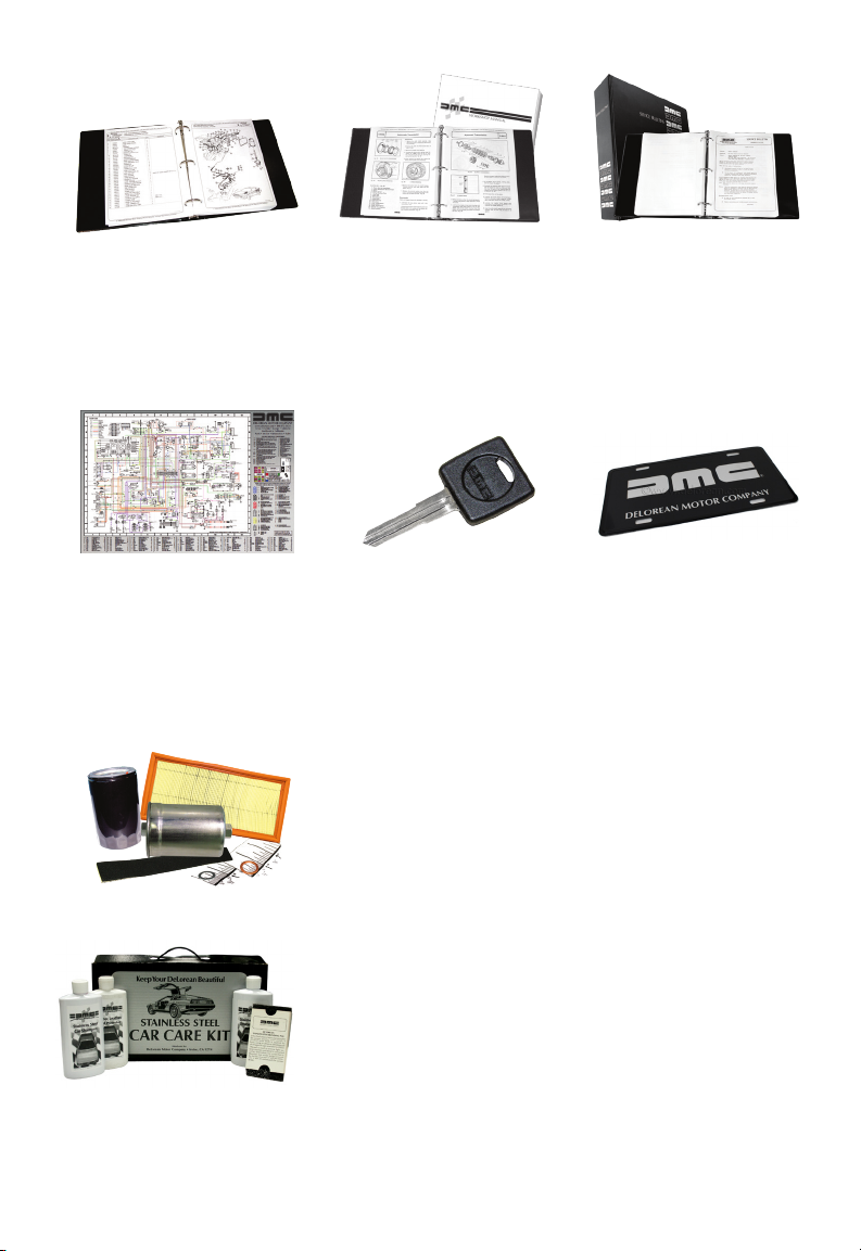
DMC Workshop Manual
Reproduction of original
factory documentation
for dealership service
personnel.
Part Number P3113096
DMC Service Bulletins
Reproductions of original
factory documentation
as written for dealership
service personnel.
Part Number P2107010
DMC Parts
Identication Manual
Updated reproduction
of original factory
documentation.
Part Number P1105010
Full Color Wiring
Diagram
Most complete & accurate
wiring diagram ever created
for the DeLorean automobile.
Part Number P6100330
DeLorean Key Blank
Fits all ignitions, cubby
boxes, original locking gas
caps and door locks for
VIN’s ending in 4200 & up.
Part Number 109100
DMC License Plate
A reproduction of the
original design used
in publicity photos by
the original DMC.
Part Number A7101002
Oil, Air and Fuel Filters
Includes sealing washers where required to do the job
right! All pieces sold separately or as a convenient kit.
Oil Filter with sealing washer������������������ Part Number 102114B
Air Filter ��������������������������������������������������������Part Number 102575
Fuel Filter w/sealing washers & pad����������Part Number 100523
Three Filter Kit (Oil, Air & Fuel) ��������������� Part Number K102575
DeLorean Stainless Steel Car Care Kit
Modern formulations of original stainless shampoo,
stainless cleaner/sealer and leather/vinyl conditioner.
Car Care Kit�����������������������������������������������Part Number A4000100
Stainless Shampoo (16 oz)�����������������������Part Number A4000121
Stainless Cleaner/Sealer (16 oz) �������������Part Number A4000111
Leather/Vinyl Conditioner (16 oz) ����������Part Number A4000131
Blending Pad (each) ���������������������������������Part Number A4000151
Blending Pad Handle �������������������������������Part Number A4000152
SS-Glow Polish ������������������������������������������Part Number A4000162
Wheel Cleaning Brush �����������������������������Part Number A4000153
3
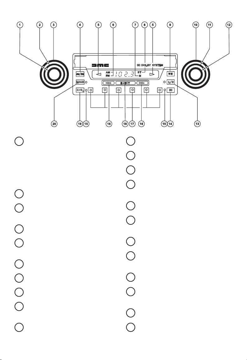
ON-OFF VOLUME CONTROL
(INNER MOST KNOB)
PUSH FOR RADIO STATION
SEEK
PUSH FOR TAPE PROGRAM
CHANGE
TREBLE CONTROL (CENTER KNOB)
BASS CONTROL (OUTTER
MOST KNOB)
AM/FM SELECTOR BUTTON
TAPE DIRECTION INDICATOR
LIGHTS
AM/FM INDICATOR LIGHTS
MEMORY INDICATOR LIGHT
STEREO INDICATOR LIGHT
MEMORY ACTIVATE –
DE-ACTIVATE BUTTON
MANUAL TUNING CONTROL
LEFT-RIGHT BALANCE CONTROL
FRONT-REAR FADER CONTROL
LOCAL/DISTANT CONTROL
DOLBY NOISE REDUCTION
BUTTON
RADIO PUSHBUTTONS
FAST FORWARD/REWIND
CONTROLS
TAPE EJECT CONTROL
TAPE EQUALIZATION BUTTON
FOR METAL TAPES
LOUDNESS CONTROL
FUNCTION LAMPS
(ON WHEN FUNCTION IS ON)
CLOCK-HOUR SET CONTROL
CLOCK-MINUTE SET CONTROL
22
21
20
19
18
17
12
11
10
9
8
4
3
2
1
5
6
7
16
15
14
13

4
RADIO OPERATION
TO TURN TAPE PLAYER OR RADIO ON
The ON-OFF switch combined with the VOLUME control,
both of which are operated by the left front knob. Turn
this knob clockwise until a “click” is heard, which indi-
cates that the radio is now “ON”. Further clockwise rota-
tion will increase the volume.
AM/FM SELECTION
The desired broadcast band is selected by the AM/FM
Selector Button which is the button marked “AM/FM”.
The radio has the FM and AM band indicators located
to the left of the Radio Frequency display and the appro-
priate indicator will light up depending on whether FM
or AM band is operating.
MANUAL STATION TUNING
This radio is equipped with an electronic tuner. To tune
to a station manually rotate the right front knob clock-
wise for up scale tuning and counterclockwise for down
scale tuning. The frequency will appear on the digital
display area of the radio. On the AM band the frequen-
cy will appear in steps of 10 KHz and on the FM band
frequency will appear in steps of 0.2 MHz. Each “click”
while rotating the manual tuning knob will be one step
on the respective broadcast band. Tune the set carefully
until you are exactly on the station. This FM receiver is
equipped with an automatic muting circuit. This circuit
lters out virtually all o station background noise when
tuning from station to station. Also, when background
noise is greater than the transmitted station signal, both
the station signal and background noise are muted
10
4
1
6

5
(ltered) out.
SEEK TUNING
The SEEK tuning feature of this radio automatically lo-
cates the next strong station available on the radio dial
when actuated. This feature operates in the up scale di-
rection. The SEEK tuning feature is activated by pushing
in the left front knob when in the radio mode. The radio
automatically locates the next strong station and stops.
This procedure can be repeated by pushing the left front
knob again. Repeat until the desired station is being re-
ceived. For maximum sensitivity of Seek Tuning, the L/D
button should be in the distant position.
TUNING PUSHBUTTONS
Each tuning pushbutton can be set to two stations, one
on the AM band and one on the FM band. This provides
a total of twelve stations which can be selected by push-
button operation. Each tuning pushbutton also has a
dual color LED light in its center. These lights allow the
user to easily locate each pushbutton at night. The lights
change from red to green to indicate the last pushbut-
ton operated.
MEMORY
Set pushbuttons as follows:
1. Select the desired broadcast band with the AM/FM
selector button
2. Carefully tune to the desired station with the manual
tuning control or by using the SEEK tuning feature
3. Press the top right button marked “ME” for approxi-
mately 3/4 seconds until the orange colored “M” ap-
pears on the display area
9
15
1
4
110
7
12

6
4. Press one of the tuning pushbuttons. The “M” on the
display area will go out indicating the button is now
preset to this station.
5. Repeat steps 2-4 for the remaining buttons.
6. Set the AM/FM selector button to the other broad-
cast band and set the six pushbuttons in the same
manner as above.
NOTE: THE ELECTRONIC CONTROL FUNCTIONS IN THE RADIO
WILL NOT OPERATE PROPERLY IF POWER TO THE RADIO IS IN-
TERRUPTED. THE POWER INTERRUPTION COULD BE CAUSED
BY THE DISCONNECTION OF THE BATTERY, OR LOW BATTERY
VOLTAGE AS MAY OCCUR IN COLD WEATHER STARTING. DIS-
CONNECTION OF THE BATTERY WILL CAUSE LOSS OF PUSH-
BUTTON STATION MEMORY AND THE TIME. THE MEMORY AND
CLOCK WILL REQUIRE RESETTING WHEN POWER IS RESTORED.
LOW BATTERY VOLTAGE WILL CAUSE FAILURE IN THE SEEK TUN-
ING OPERATION. THE SEEK TUNING WILL OPERATE PROPERLY
WHEN POWER IS RESTORED.
STEREO INDICATOR LIGHT
The FM Stereo light, “ST”, is located on the right side of
the display area. This light will glow whenever the radio
is tuned to an FM stereo station whose broadcasting sig-
nal is of sucient strength. If the Stereo signal begins
to weaken the radio will automatically blend to monau-
ral reception. The mono mode will increase the radio’s
ability to receive the weak signal. As the signal strength
returns to a sucient level the radio will automatically
return to the Stereo mode.
LOCAL/DISTANT SELECTOR
The center button on the right side of the radio marked
“L/D” is the Local/Distant Selector. When the small green
indicator light is on the radio is in the ‘Distant’ mode.
8
13
4

7
When the indicator light is o, the radio is in the ‘Local’
mode. This switch allows the user to discriminate the
strong (‘Local’ position) from the weak stations (‘Distant’
position) in the FM mode.
When the radio is in the Seek Tuning mode, this feature
allows the user to discriminate the strong station from
the weak stations on both the AM and FM bands. Your
radio should be in the ‘DISTANT’ mode for best recep-
tion under most conditions, an exception would be in an
urban area with tall buildings.
TREBLE CONTROL
The treble response can be adjusted to the desired level
with the middle knob on the left side of the radio. Ro-
tating clockwise increases the treble and rotating coun-
terclockwise decreases the response. There is a detent
position at the middle point of the knob’s rotation.
BASS CONTROL
The bass response can be adjusted to the desired level
with the rear knob on the left side of the radi. Rotating
clockwise increases the bass and rotating counterclock-
wise decreases the response. There is a detent position
at the midpoint of the knob’s rotation.
BALANCE CONTROL (LEFT-RIGHT)
Adjust the balance control with the right middle knob
just behind the manual tuning control to the point
where the volume appears equal between the left and
right speakers. This control has a center detent position
where the volume is exactly equal between the left and
right audio outputs of the unit.
11
3
2

8
FADER CONTROL (FRONT-REAR)
Adjust the fader control, the rear knob on the right side
of the radio to the point where the volume appears
equal between the front and rear speakers.
LOUDNESS CONTROL
Low volume labels are deceptive to the human ear in
that the ear has a tendency not to hear the low and high
frequencies (bass & treble) as clearly as the mid-range.
The Loudness Control provides boost to the low and
high frequencies to compensate for the ear’s decien-
cies. The Loudness Control is the middle button on the
left side of the radio marked “LOUD”. When the green
indicator lamp is ON, the Loudness Control is ON. When
the Lamp is OFF, the control is OFF.
CLOCK OPERATION
With the ignition switch in the ON position and the radio
on or o, the time of day will be displayed on the radio
display. The radio frequency can be displayed by press-
ing the “CRO2” button or the Dolby NR button .
The time will reappear after about ve seconds. The
time is also displayed when the tape player is operating.
TO SET CLOCK
The time of day must be on the display to set the clock.
The hour is set by pressing the small button to the
left of the fast forward/rewind buttons, with a pointed
object such as a pencil point. The minutes are set in the
same manner by pressing the small button to the
right of the fast forward/rewind buttons.
22
21
19
18
12
14

9
TAPE PLAYER OPERATION
Insert the tape cassette into the tape slot until it locks
into position. The unit is automatically switched to tape
player operation and one of the green tape direction in-
dicators located on either side of the display area
will be on. The various lights shown when the radio is
on will not light up. They will come back on when tape is
ejected and the lights relating to the cassette operation
will go o.
PROGRAM CHANGE CONTROL
When the tape program reaches its conclusion the tape
player will automatically reverse the tape direction and
play the other program. To manually change the tape
direction, push the Volume control knob . The proper
tape direction indicator will light.
REWIND
To rewind the tape, depress one of the two control but-
tons marked with arrows. The button with arrows point-
ing opposite the direction of the tape, as indicated by
the lit tape direction indicator light will rewind the
tape in order to repeat sections of the tape program.
The button will lock in position when pressed fully in-
ward. It can be released by partially pushing in the Eject
button. When the button is released, the unit will play at
normal speed.
FAST FORWARD
The control button marked with arrows pointing in the
same direction as the tape, as indicated by the lit tape
direction indicator light, will increase the tape speed
5
16
5
5
5
16
1
1

10
when depressed. This function allows the location of
other sections of the tape program. The button will lock
when depressed fully inward. It can be released by par-
tially pishing in the Eject button. When the button is re-
leased, the unit will play at normal speed.
EJECT
To eject the tape cassette push in rmly on the “EJECT”
button and the cassette will be partially ejected from the
tape slot. The unit is automatically switched to radio op-
eration. An important point - do not leave the cassette
in the play position when you turn the radio or the car
engine o.
DOLBY* NR (NOISE REDUCTION) CONTROL
This tape player is equipped with a noise reduction cir-
cuit developed by Dolby Laboratories. It reduces to a
minimum the noise commonly referred to as “tape hiss”
and improves the reproduction of the high frequency
sounds. This circuit will best aect tapes recorded us-
ing the Dolby NR process. They will be identied by the
“Double-D” symbol and the words “DOLBY SYSTEM”
printed on the label. The tape player’s Dolby NR circuit
is controlled by the bottom button on the right side of
the radio marked with the “Double-D” symbol. Press
the button when playing tapes recorded with the Dolby
Noise Reduction process. The function is ON when the
lamp is ON.
*Noise Reduction System manufactured under license from
Dolby Laboratories Licensing Corporation. ‘DOLBY’ and the
double-D symbol are trademarks of Dolby Laboratories
Licensing Corporation.
17
14

11
TAPE EQUALIZATION CONTROL
The button in the lower left corner of the radio marked
“Cr02” selects the proper tape equalization value of 120
microseconds for normal tapes and 70 microseconds
for chrome tapes. Push the button when using hi-bias
chrome tape to achieve more faithful reproduction. The
function is ON when the green light is ON.
18
ASI RADIO NOSE PIECE
Part Number 110691
ASI RADIO FACEPLATE
Part Number 110699
PARTS
POWER ANTENNA
MOTOR & MAST
Part Number 110971

Texas
15023 Eddie Drive
Humble, TX 77396
800/USA-DMC1 • 281-441-2537
DeLorean.com
Midwest
990 Lutter Drive
Crystal Lake, IL 60014
877/DMC-MIDW • 815-459-6439
DMCMidwest.com
California
7402 Prince Drive
Huntington Beach, CA 92647
714-842-0040
DMCCalifornia.com
Florida
11144 Satellite Boulevard
Orlando, FL 32837
888/81DMC12 • 407-203-2300
DMCFlorida.com
© 2021 Copyright DeLorean Motor Company. The stylized DMC and DeLorean logos are registered trademarks of
the DeLorean Motor Company. Availability, pricing and specications subject to change.
DELOREAN M
OTOR COMPANY
Table of contents


