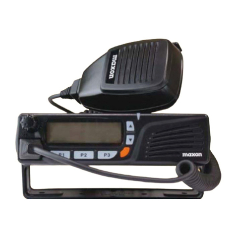
Maxon CM10 User manual


User Manual CM10
Page 2 of 55
English
Contents
Specification………………………………………………………………………………………………………………………3
Control and Operation ……………....……………………………………………………………………………………4-5
Microphone…………………………………………………………………………………………………………………………6
Installation …………………………………………………………………………………………………………………………7
Installation of Main Unit ………………………………………………………………………………………………………7
Installation of Antenna ……………………………………………………………………………………………..………..7
Operational Test …………………………………………………………………………………………………………………8
Frequency Bands Table ……………………………………………………………………………………………………….8
Frequency Band Selection ……………………………………………………………………………………………………8
Reset ………………………………………………………………………………………………………………………………..9
Table of Restrictions …………………………………………………………………………………………………………50
Updated Information on National Restrictions ……………………………………………………………………..51
Diagrams ………………………………………..………………………………………………………………………....52-54
Declaration of Conformity ………………………………………………………………………………..………………..55
C
C
Co
o
on
n
nt
t
te
e
en
n
nt
t
ts
s
s

User Manual CM10
Page 3 of 55
English
Specification
GENERAL
Channels…………………………………………………..……...……………………………......…. 40 Ch AM/FM 4W
Frequency Range………………………………...………………………………………..….26.565 to 27.99125 MHz
Frequency Control……………………………………………………..……………………………………………….……PLL
Operating Temperature Range……………………..…………………………………………..…….….-10°/ +55°C
DC Input Voltage…………………………...…………………...…………………………………….…13.2 V DC ±15%
Size………………………………………….………………………………………...…….180(L) X 35(H) X 140(D) mm
Weight…………………………………………………………...……………………………………………………..……750 g
RECEIVER
Receiving System……………………………………………...…………...….Dual Conversion Super Heterodyne
Intermediate Frequency…………………………………………………….1st IF: 10.695 MHz, 2nd IF: 455 MHZ
Sensitivity………………………………………………….………...………….0.5 μV for 20 db SINAD in FM mode
Audio Distortion………………………………………………………………..……………....Less Than 8% @ 1 KHz
Image Rejection…………………………….………………….………………………………………………………...65 dB
Adjacent Channel Rejection……………………………………..………………………………………………..….65 dB
Signal/ Noise Ratio……………………………………………………..………………………………………………..45 dB
Current Drain at standby………………………………………….…………………………………………….....150 mA
Current Drain at maximum audio…………………………………………………..………………………......820 mA
TRANSMITTER
Output Power…………………………………………………………………………………..……...….4W @ 13.2 V DC
Modulation…………………………………………………………………………………...………FM: 1.8 KHz ±0.2 KHz
Frequency response…………………………………………………………………………...From 400 Hz to 2.5 KHz
Output impedance………………………………………………………….…..…………………RF 50 ohm Unbalance
Signal/ Noise Ratio……………………………………………………….………………………………………..40 dB MIN
Current Drain…………………………………………………………………………………………………….…….1100 mA
S
S
Sp
p
pe
e
ec
c
ci
i
if
f
fi
i
ic
c
ca
a
at
t
ti
i
io
on
n
on

User Manual CM10
Page 4 of 55
English
Control & Operation
Front Panel
1. AM/FM Selector
This key allows the user to select the AM or FM operating mode in both RX and TX. The AM/FM
operating mode selection is possible only if it is enabled on the programmed frequency band.
2. CH9/CH19 Selector
This key allows quick access to one of the two pre-programmed emergency channels (CH9 and
CH19). Each time this key is pressed, the radio will select CH9, then CH19, then again the normal
operating channel. When one of the emergency channels is selected, EMG will appear on the LED
display. The operating mode (AM or FM) for the emergency channels is factory pre-programmed.
3. TX Indicator
This red LED indicator lights up when the radio is in transmit mode.
4. FM Indicator
This green LED indicator lights up when the radio is in FM mode.
5. LED Display
The large two-digit LED display indicates the operating channel and the programmed frequency
band code.
C
C
Co
o
on
n
nt
t
tr
r
ro
o
ol
l
l
&
&
&
O
O
Op
p
pe
e
er
r
ra
a
at
t
ti
i
io
o
on
n
6. DN (Down) Key
This key allows selection of the operating channel in decrements. By keeping this key pressed,
the quick channel selection mode will be enabled.
7. UP (Up) Key
This key allows the selection of the operating channel in increments. By keeping this key pressed,
the quick channel selection mode will be enabled.
n

User Manual CM10
Page 5 of 55
English
8. SQUELCH Control
The SQUELCH control allows the operator to silence the radio, blocking the background noise,
when no signals are received on the operating channel. Turn the SQUELCH knob clockwise until
the background noise stops. Turn the SQUELCH knob counterclockwise (SQUELCH opening) to
listen to the weakest signals. If this switch is turned off the Automatic Squelch Control will be
activated.
9. OFF / VOLUME Control
Use this knob to switch the radio ON and OFF, as well as to adjust the receiver volume to the
desired level. To adjust the receiver volume (if no signals are received on the operating channel),
open the SQUELCH and then adjust the receiver volume using the background noise as a
reference.
10. Microphone Connector
Insert the microphone lead to this connector and turn the connector ring in a clockwise to lock it.
Rear
11. EXT (External) Speaker Jack
This jack is for connecting an (optional) external speaker.
12. ANTENNA Connector
Please refer to the section ANTENNA INSTALLATION (page 6).
13. 13.2VDC POWER CORD
C
C
Co
o
on
n
nt
t
tr
r
ro
o
ol
l
l
&
&
&
O
O
Op
p
pe
e
er
r
ra
a
at
t
ti
io
on
n
ion

User Manual CM10
Page 6 of 55
English
Microphone
14. PTT (Push-to-Talk) Key
Transmitter key, press the PTT key to transmit and release to return to receive mode.
15. MICROPHONE Plug
The 4-pin microphone connector (with locking ring), this connects the handset to the microphone
connector on the front panel of the radio.
M
M
Mi
i
ic
c
cr
r
ro
o
op
p
ph
h
ho
o
on
n
ne
e
e

User Manual CM10
Page 7 of 55
English
Installation
Before installing the main unit in a vehicle, identify the most convenient location, so that the
radio will be easy to reach and comfortable to operate, without disturbing or interfering with
driving the vehicle. Use the supplied bracket and hardware to install the radio. The bracket
screws must be well tightened to prevent loosening with the vehicle vibrations. The car mounting
bracket can be installed over or below the radio and the radio may be tilted as desired according
to the specific type of installation (under dashboard or track cabin roof installation).
Installation of Main Unit
Before connecting the radio to the vehicles electricity supply, ensure the radio is switched off,
with the OFF/VOLUME knob completely turned counter clockwise at the OFF position. The DC
power cable of the radio is complete with a fuse holder with the fuse located on the red positive
(+) wire. Connect the DC power cable to the vehicles electricity supply, pay special attention with
respect to correct polarity, even if the radio is protected against polarity inversion. Connect the
red wire to the positive (+) pole and the black wire to the negative (-) pole of the vehicles
electricity supply. Make sure that the wires and terminals are firmly and stably connected, in
order to prevent cables from disconnecting or causing short circuits.
Installation of Antenna
A specific mobile antenna adjusted for 27 MHz frequency range must be used. The antenna
installation must be carried out by a specialist technician or service centre. Please pay special
attention to carefully install the antenna on the vehicle with perfect connection to ground. Before
connecting the antenna to the radio, it is necessary to check the correct operation of the antenna
with low standing wave ratio (S.W.R.), using appropriate instruments. If not, the transmitter
circuit of the radio could be damaged. The antenna must be installed on the highest part of the
vehicle, free from obstacles and as far away as possible from any source of electric or
electromagnetic noise. The RF antenna coaxial cable must not be damaged or pressed on its way
between antenna and the radio. The correct operation of the antenna and the low standing wave
ratio (S.W.R.) must be checked periodically. Connect the RF antenna coaxial cable to the antenna
connector, located on the rear side of the radio.
I
I
In
n
ns
s
st
t
ta
a
al
l
ll
l
la
a
at
t
ti
io
on
n
ion
User Manual CM10
Page 8 of 55
English
Operational Test
Once radio has been connected to the vehicles electricity supply and to the antenna, the correct
operation of the system may be checked. Please proceed as follows:
1) Check that the power cable is correctly connected.
2) Check that the RF antenna coaxial cable is correctly connected.
3) Connect the microphone to the connector (located on the front side of the radio).
4) Rotate the SQUELCH knob counter clockwise.
5) Turn radio on using the OFF/VOLUME knob and adjust volume to the desired level.
6) Select the desired channel, using the channel selector keys.
7) Rotate the SQUELCH knob clockwise, to cut the background noise.
8) Press the PTT key to transmit and release it to receive.
If this check is successful the transceiver will work correctly.
Fre
q
uenc
y
Bands Table
The CM10 transceiver includes an advanced multi-standard programmable circuit, which allows
programming on different frequency bands, specifications and operating modes, in conformity
with the regulations in the country where the product is used. 8 programmable frequency bands
are available, as per the below table:
COUNTRY
CODE COUNTRY SPECIFICATIONS (CH, operating modes, TX power)
01 ITALY / SPAIN 40CH AM / FM 4W
02 ITALY 36CH AM / FM 4W
03 GERMANY 80CH FM 4W - 12CH AM 1W
04 GERMANY 40CH FM 4W - 12CH AM 1W
05 EUROPE / FRANCE 40CH FM 4W - 40CH AM 1W
06 CEPT 40CH FM 4W
07 UK 40CH FM 4W UK FREQUENCIES -40CH FM 4W CEPT FREQUENCIES
08 POLAND 40CH AM / FM 4W POLISH FREQUENCIES
Attention! This radio has been factory pre-programmed on the CE frequency band (CEPT 40CH FM 4W),
as this standard is currently accepted in all the European countries. Please refer to the information table at
page 1 (Restrictions on the use of CB transceivers).
F
F
Fr
r
re
e
eq
q
qu
u
ue
e
en
n
nc
c
cy
y
y
b
b
ba
a
an
n
nd
d
ds
s
s
t
t
ta
a
ab
b
bl
le
e
Fre
q
uenc
y
Band Selection/Pro
g
rammin
g
This two-way CB radio must be programmed and exclusively used on a frequency band allowed in
the country where the product is used. When radio is switched ON, the current programmed
frequency band code will be displayed (blinking) for around 3 seconds. To program a different
frequency band, proceed as follows:
1) Turn the radio OFF.
2) Press and hold the UP key, then turn the radio ON using the OFF/VOLUME knob.
3) The current frequency band code will blink on the display.
4) Now select the new desired frequency band code by pressing the UP or DN key; during the
frequency band selection process, the frequency band display will blink at a faster rate.
5) Press and hold the DN key to confirm and store the new selected frequency band code.
le

User Manual CM10
Page 9 of 55
English
Reset
To restore the original factory settings (CE frequency brand), follows the below process:
1) Turn the radio OFF.
2) Press and hold the DN key, then turn the radio ON using the OFF/VOLUME knob.
3) The CE frequency band code (code 06) will blink on the display for 3 seconds.
R
R
Re
e
es
se
et
t
set

User Manual CM10
Page 10 of 55
Español
Contenido
Especificaciones…………………………………………………………………………………………………………………11
Control y utilización……………....…………………………………………………………………..…………………12-13
Micrófono……………………………………………………………………………………………………………………….…14
Instalación………………………………………………………………………………………………………………………..15
Instalación de la unidad principal………………………………………………………………………………………..15
Instalación de la antena……………………………………………………………………………………………………..15
Prueba de funcionamiento……………………………………………………………………………………………….…16
Tabla de bandas de frecuencia……………………………………………………………………………………………16
Selección de bandas de frecuencia………………………………………………………………………………………16
Restablecimiento……………………………………………………………………………………………………………….17
Tabla de restricciones………………………………………………………………………………………………………..50
Información actualizada sobre restricciones nacionales ………………………………………………………..51
Diagramas……………………………………..………………………………………………………………………....52-54
Declaración de conformidad…………………………………………………………………………..………………..55
C
C
Co
o
on
n
nt
t
te
e
en
n
ni
i
id
d
do
o
o

User Manual CM10
Page 11 of 55
Español
Especificaciones
GENERALES
Canales…………………………………………………..……...………………………......…. 40 canales AM/FM 4W
Rango de frecuencias………………………...………………………………………..….26.565 a 27.99125 MHz
Control de frecuencia……………………………………………………..………………………………………………PLL
Rango de temperaturas de funcionamiento…..…………………………………………..…….….-10°/ +55°C
Tensión de entrada de CC……………...…………………...…………………………………….…13,2 V CC ±15%
Tamaño………………………………….………………………………………...…….180(L) X 35(A) X 140(P) mm
Peso……………………………………………………………...……………………………………………………..……750 g
RECEPTOR
Sistema de recepción……………………………………………...…………Superheterodino de conversión dual
Frecuencia intermedia …………………………………………………….1ª IF: 10.695 MHz, 2ª IF: 455 MHZ
Sensibilidad…………………………………………….………...………….0,5 μV para 20 db SINAD en modo FM
Distorsión de sonido…………………………………………………………..……………....Inferior al 8% @ 1 KHz
Rechazo de imagen……………………….………………….………………………………………………………...65 dB
Rechazo de canal adyacente…………………………………..………………………………………………..….65 dB
Relación señal/ruido…………………………………………………..………………………………………………..45 dB
Consumo de corriente en standby…………………………….…………………………………………….....150 mA
Consumo de corriente con máximo nivel de audio…….……………………………………………....0,820 mA
TRANSMISOR
Potencia de salida……………...…………………...…………………………………….………...….4W @ 13,2 V DC
Modulación…………………………………………………………………………………...………FM: 1.8 KHz ±0.2 KHz
Respuesta de frecuencia…………………….......………………………………………..…...De 400 Hz a 2.5 KHz
Impedancia de salida…………………………………………………….…..…………RF 50 ohmios, desequilibrio
Relación señal/ruido………………………………………………….……………………………………….….40 dB MÍN
Consumo de corriente……………………………………………………………………………………….…….1100 mA
E
E
Es
s
sp
p
pe
e
ec
c
ci
i
if
f
fi
i
ic
c
ca
a
ac
c
ci
i
io
o
on
n
ne
es
s
es

User Manual CM10
Page 12 of 55
Español
Control y utilización
Panel delantero
1. Selector AM/FM
Este control permite al usuario seleccionar el modo de funcionamiento en AM o FM tanto en RX
como en TX. La selección de modo de función AM/FM sólo es posible si está activada en la banda
de frecuencias programada.
2. Selector CH9/CH19
Este control permite un acceso rápido a uno de los dos canales de emergencia preprogramados
(CH9 y CH19). Cada vez que se pulsa este botón, la radio selecciona CH9, luego CH19 y,
después, de nuevo el canal de funcionamiento normal. Cuando se selecciona uno de los canales
de emergencia, aparece EMG en la pantalla LED. El modo de funcionamiento (AM o FM) para los
canales de emergencia está preprogramado en fábrica.
3. Indicador TX
El indicador LED rojo se ilumina cuando la radio está en modo de transmisión.
4. Indicador FM
Este indicador LED verde se ilumina cuando la radio está en modo FM.
5. Pantalla LED
La pantalla LED grande de dos dígitos indica el canal de funcionamiento y el código de banda de
frecuencia preprogramada.
C
C
Co
o
on
n
nt
t
tr
r
ro
o
ol
l
l
y
y
y
u
u
ut
t
ti
i
il
l
li
i
iz
z
za
a
ac
c
ci
i
ió
ó
ón
n
6. Botón Abajo
Este botón permite la selección del canal de funcionamiento en decrementos. Al mantenerlo
pulsado, se activa el modo de selección rápida de canal.
7. Botón Arriba
Este botón permite la selección del canal de funcionamiento en incrementos. Al mantenerlo
pulsado, se activa el modo de selección rápida de canal.
n

User Manual CM10
Page 13 of 55
Español
8. Control SQUELCH
El control SQUELCH permite al operador silenciar la radio, bloqueando el ruido de fondo, cuando
no se recibe ninguna señal en el canal de funcionamiento. Gire el control SQUELCH en el sentido
de las agujas del reloj hasta que desaparezca el ruido de fondo. Gire el control SQUELCH en
sentido contrario al de las agujas del reloj (apertura de SQUELCH) para escuchar las señales más
débiles. Si este interruptor está apagado, se activará el control automático de Squelch.
9. Control OFF / VOLUME
Utilice este control circular para encender y apagar la radio, así como para ajustar el volumen del
receptor con el nivel deseado. Para ajustar el volumen del receptor (si no se recibe ninguna señal
en el canal de funcionamiento), abra el SQUELCH y luego ajuste el volumen del receptor
sirviéndose del ruido de fondo como referencia.
10. Conector para micrófono
Enchufe el cable del micrófono a este conector y gire el anillo de conexión en el sentido de las
agujas del reloj para bloquearlo.
Parte posterior
11. Conector de altavoz EXT (externo)
Este conector permite la conexión de un altavoz externo (opcional).
12. Conector de antena (ANTENNA)
Consulte la sección INSTALACIÓN DE LA ANTENA (página 6).
13. CABLE DE CORRIENTE DE 13,2 VCC
C
C
Co
o
on
n
nt
t
tr
r
ro
o
ol
l
l
y
y
y
u
u
ut
t
ti
i
il
l
li
i
iz
z
za
a
ac
c
ci
i
ió
ó
ón
n
n

User Manual CM10
Page 14 of 55
Español
Micrófono
14. Tecla PTT (Push-to-Talk)
Tecla de transmisor; pulse la tecla PTT para transmitir y suéltela para regresar al modo de
recepción.
15. Conector para MICRÓFONO
El conector para micrófono de 4 patillas (con anillo de bloqueo) conecta el terminal de mano al
conector para micrófono situado en el panel delantero de la radio.
M
M
Mi
i
ic
c
cr
r
rÓ
Ó
Óf
f
fo
o
on
no
o
no

User Manual CM10
Page 15 of 55
Español
Instalación
Antes de instalar la unidad principal en un vehículo, determine cuál es el lugar más cómodo, de
manera que la radio sea fácilmente accesible y se pueda operar con ella con comodidad y sin
interferir en la conducción del vehículo. Utilice el soporte y el material suministrados para instalar
la radio. Los tornillos del soporte deben apretarse bien para evitar que se suelten con las
vibraciones del vehículo. El soporte para montaje en vehículo puede instalarse encima o debajo
de la radio. La radio puede inclinarse como se desee para adaptarla al tipo de instalación de que
se trate (instalación debajo del salpicadero o en el techo de la cabina de un camión).
Instalación de la unidad
p
rinci
p
al
Antes de conectar la radio a la fuente de alimentación eléctrica del vehículo, asegúrese de que la
radio está apagada, con el control circular OFF/VOLUME totalmente girado en sentido contrario al
de las agujas del reloj, en la posición OFF. El cable de alimentación de CC de la radio está
provisto de un portafusible. El fusible está situado en el hilo rojo positivo (+). Conecte el cable de
alimentación de CC a la fuente de alimentación del vehículo. Preste especial atención a la
polaridad aunque la radio disponga de protección contra inversiones de polaridad. Conecte el hilo
rojo al polo positivo (+) y el hilo negro, al polo negativo (-) de la fuente de alimentación del
vehículo. Asegúrese de que los hilos y terminales están conectados de manera firme y estable
para evitar que los cables se desconecten o provoquen cortocircuitos.
Instalación de la antena
Debe utilizarse una antena móvil específica ajustada al rango de frecuencias de 27 MHz. La
instalación de la antena deberá realizarla un técnico o centro de servicio especializado. Tenga
especial cuidado al instalar la antena en el vehículo para que ésta esté perfectamente conectada
a tierra. Antes de conectar la antena a la radio, es necesario comprobar el correcto
funcionamiento de la antena con baja relación de onda estacionaria (S.W.R.) mediante el uso de
los instrumentos adecuados. De no ser así, podría dañarse el circuito del transmisor de la radio.
La antena debe instalarse en la parte más alta del vehículo, libre de obstáculos y lo más alejada
posible de cualquier fuente de electricidad o ruido electromagnético. El cable coaxial de la antena
RF no debe dañarse ni presionarse en su tendido desde la antena hasta la radio. El correcto
funcionamiento de la antena y la baja relación de onda estacionaria (S.W.R.) deberán
comprobarse periódicamente. Conecte el cable coaxial de la antena RF al conector de antena,
situado en la parte posterior de la radio.
I
I
In
n
ns
s
st
t
ta
a
al
l
la
a
ac
ci
ió
ón
n
ción

User Manual CM10
Page 16 of 55
Español
Prueba de funcionamiento
Una vez conectada la radio a la fuente de alimentación del vehículo y a la antena, deberá
comprobarse el correcto funcionamiento del sistema. Proceda del siguiente modo:
1) Compruebe que el cable de alimentación esté correctamente conectado.
2) Compruebe que el cable coaxial de antena RF esté correctamente conectado.
3) Conecte el micrófono al conector (situado en la parte delantera de la radio).
4) Gire el control SQUELCH en sentido contrario al de las agujas del reloj.
5) Encienda la radio mediante el control circular OFF/VOLUME y ajuste el volumen al nivel
deseado.
6) Seleccione el canal deseado empleando los botones de selección de canal.
7) Gire el control SQUELCH en el sentido de las agujas del reloj para cortar el ruido de fondo.
8) Pulse la tecla PTT para transmitir y suéltela para recibir.
Si esta comprobación finaliza correctamente, el transceptor funciona correctamente.
Tabla de bandas de frecuencia
El transceptor CM10 incluye un circuito programable multiestándar avanzado que permite la
programación de diferentes bandas de frecuencia, especificaciones y modos de funcionamiento,
de conformidad con la normativa del país en que se utilice el producto. Hay disponibles 8 bandas
de frecuencias programables, conforme a la siguiente tabla:
CÓDIGO DE
PAÍS PAÍS ESPECIFICACIONES (Canales, modos operativos, potencia de TX)
01 ITALIA / ESPAÑA 40CH AM / FM 4W
02 ITALIA 36CH AM / FM 4W
03 ALEMANIA 80CH FM 4W - 12CH AM 1W
04 ALEMANIA 40CH FM 4W - 12CH AM 1W
05 EUROPA / FRANCIA 40CH FM 4W - 40CH AM 1W
06 CEPT 40CH FM 4W
07 REINO UNIDO 40CH FM 4W FRECUENCIAS DE RU -40CH FM 4W FRECUENCIAS CEPT
08 POLONIA 40CH AM / FM 4W FRECUENCIAS POLACAS
T
T
Ta
a
ab
b
bl
l
la
a
a
d
d
de
e
e
b
b
ba
a
an
n
nd
d
da
a
as
s
s
d
d
de
e
e
f
f
fr
r
re
e
ec
c
cu
u
ue
e
en
n
nc
ci
ia
a
¡Atención! Esta radio se ha preprogramado en fábrica en la banda de frecuencias CE (CEPT 40CH FM
4W), ya que este estándar es aceptado actualmente por todos los países europeos. Consulte la información
de la tabla contenida en la página 1 (Restricciones al uso de transceptores CB).
Selección/
p
ro
g
ramación de bandas de frecuencias
Esta radio CB bidireccional debe programarse y utilizarse exclusivamente en una banda de
frecuencias permitida en el país en el que se utiliza el producto. Al encender la radio, el código de
banda de frecuencias programado actualmente aparece (intermitentemente) durante unos 3
segundos. Para programar otra banda de frecuencias diferente, siga estos pasos:
1) Apague la radio.
2) Mantenga pulsado el botón Arriba y encienda la radio empleando el control circular
OFF/VOLUME.
3) Aparecerá en pantalla intermitentemente el código de banda de frecuencias actual.
4) Seguidamente, seleccione el código de banda de frecuencias deseado pulsando el botón Arriba
o Abajo; durante el proceso de selección de la banda de frecuencias, la visualización de la banda
de frecuencias parpadeará más rápido.
5) Mantenga pulsado el botón Abajo para confirmar y almacenar el código de banda de
frecuencias seleccionado.
cia

User Manual CM10
Page 17 of 55
Español
Restablecimiento
Para restaurar la configuración original de fábrica (banda de frecuencias CE), siga este
procedimiento:
1) Apague la radio.
2) Mantenga pulsado el botón Abajo y luego encienda la radio empleando el control circular
OFF/VOLUME.
3) El código de banda de frecuencias CE aparecerá intermitentemente en pantalla durante 3
segundos.
R
R
Re
e
es
s
st
t
ta
a
ab
b
bl
l
le
e
ec
c
ci
i
im
m
mi
i
ie
e
en
n
nt
to
o
to

User Manual CM10
Page 18 of 55
Italiano
Sommario
Specifiche……………………………………………………………………………………………………………………...…19
Comandi e operatività ……………....………………………………………………………………………………...20-21
Microfono ……………....………………………………………………………..................…………………………..…22
Installazione …………………………………………………………………………………………………………………….23
Installazione dell'unità principale…………………………………………………………………………………….…..23
Installazione dell'antenna……………………………………………………………………………………………………23
Test di operatività …………………………………………………………………………………………………….………23
Tabella delle bande di frequenza ………………………………………………………………………………………..24
Selezione delle bande di frequenza ………………………………………………………………………………….…24
Ripristino …………………………………………………………………………………………………………………………25
Tabella delle limitazioni …………………………………………………………………………………………………….50
Informazioni aggiornate sulle restrizioni nazionali ………………………………………………………………..51
Schemi …………………………………………..……………………………………………………………………….....52-54
Dichiarazione per l'utente ……………………………………………………………………………………..……….…55
S
S
So
o
om
m
mm
m
ma
a
ar
r
ri
i
io
o
o

User Manual CM10
Page 19 of 55
Italiano
Specifiche
INFORMAZIONI GENERALI
Canali…………………………………………………..……...……………………………......…. 40 Ch AM/FM 4W
Gamma di frequenza………………………………...……………………………....da 26.565 a 27.99125 MHz
Controllo della frequenza……………………………………………………..……………………………………....…PLL
Intervallo di temperatura operativa……………………..………………………………………….....-10°/ +55°C
Voltaggio in ingresso CC…………………………...…………………...……………………………13,2 V CC ±15%
Dimensioni……………………………….……………………………………180(larg.) X 35(alt.) X 140(prof.) mm
Peso…………………………………………………………...……………………………………………………..……750 g
RICEVITORE
Sistema di ricezione……………………………………...…………...….Supereterodina a doppia conversione
Frequenza intermedia…………………………………………………….1°FI: 10.695 MHz, 2°FI: 455 MHZ
Sensibilità…………………………………………….………...………….0,5 μV per 20 db SINAD in modalità FM
Distorsione audio……………………………………………………………..……………....Inferiore all'8% @ 1 KHz
Reiezione immagine…………………………….………………….……………………………………………………65 dB
Reiezione canale adiacente……………………………………..………………………………………………..….65 dB
Rapporto segnale/ rumore…………………………………………………..……………………………………....45 dB
Consumo di corrente in standby..…………………………….…………………………………………….....150 mA
Consumo di corrente con l'audio al massimo............…….……………………………………………...820 mA
TRASMETTITORE
Potenza in uscita……………………………………………………………………………..……...….4W @ 13,2 V CC
Modulazione…………………………………………………………………………………...………FM: 1.8 KHz ±0.2
KHz
Risposta in frequenza………………………………………………………………………….....Da 400 Hz a 2.5 KHz
Impedenza di uscita…………………………………………………….…..………………RF 50 ohm non bilanciata
Rapporto segnale/ rumore…………………………………………………..…………………………………40 dB MIN
Consumo di corrente..…………………………….………………………………………………………………1100 mA
S
S
Sp
p
pe
e
ec
c
ci
i
if
f
fi
i
ic
c
ch
he
e
he

User Manual CM10
Page 20 of 55
Italiano
Comandi e operatività
Pannello
frontale
1. Tasto di selezione AM/FM
Questo tasto consente all'utente di selezionare la modalità AM o FM sia in RX che in TX. È
possibile selezionare la modalità AM/FM solo se questa è abilitata nella banda di frequenza
programmata.
2. Tasto di selezione canali CH9/CH19
Questo tasto consente di accedere rapidamente a uno dei due canali di emergenza pre-
programmati (CH9 e CH19). Ogni volta che si preme questo tasto, la radio selezionerà CH9,
quindi CH19 e successivamente il canale operativo normale. Quando viene selezionato uno dei
due canali di emergenza, sul display LED apparirà EMG (emergenza). La modalità operativa (AM o
FM) per i canali di emergenza è pre-programmata come settaggio di fabbrica.
3. Spia TX
Questa spia LED rossa si illumina quando la radio è in modalità di trasmissione.
C
C
Co
o
om
m
ma
a
an
n
nd
d
di
i
i
e
e
e
o
o
op
p
pe
e
er
r
ra
a
at
t
ti
i
iv
v
vi
i
it
t
tà
à
à
4. Spia FM
Questa spia LED verde si illumina quando la radio è in modalità FM.
5. Display LED
Il display LED a due cifre indica il canale operativo e il codice della banda di frequenza
programmata.
6. Tasto Giù
Questo tasto consente la selezione del canale operativo in ordine decrescente. Tenendolo
premuto verrà abilitata la modalità di selezione rapida dei canali.
7. Tasto Su
Questo tasto consente la selezione del canale operativo in ordine crescente. Tenendolo premuto
verrà abilitata la modalità di selezione rapida dei canali.
Other manuals for CM10
3
Table of contents
Languages:
Other Maxon Radio manuals

Maxon
Maxon SD-270 Series User manual

Maxon
Maxon SM5102 User manual

Maxon
Maxon MCB-100 WXD User manual

Maxon
Maxon RSS-119 User manual

Maxon
Maxon SP-510 User manual

Maxon
Maxon MBR-400 User manual

Maxon
Maxon SP-6102 User manual

Maxon
Maxon SL100K User manual

Maxon
Maxon SM-2402 User manual

Maxon
Maxon PM200 User manual

Maxon
Maxon MCB-10A User manual

Maxon
Maxon SP-0402 User manual

Maxon
Maxon SP-120 Series User manual

Maxon
Maxon SM-2000E Series User manual

Maxon
Maxon SP-200 Series User manual

Maxon
Maxon MBR-400 User manual

Maxon
Maxon SL7000 User manual

Maxon
Maxon SL-70W Series User manual

Maxon
Maxon CM10 User manual

Maxon
Maxon SD-171E Operator's manual