866.266.2826
INTRUSION • FIRE • ACCESS • NETWORKS
www.DMP.com 2500 North Partnership Boulevard
Designed, Engineered and
Assembled in Springfield, Mis-
souri using U.S. and global
components.
Springeld, Missouri 65803-8877
LT-1055INT © 2018 Digital Monitoring Products, Inc.
18095
Specications
Battery
Life Expectancy 5-7 years
Type 3.0V CR123
Transmit Condition Alarm, Low Battery
Mounting height 8’ (2.4m)
Frequency Range 863-869MHz
Dimensions
2.7” W x 1.77” D x 4.33” H
6.9W x 4.5D x 11H cm
Color White
Patents
U.S. Patent No. 7,239,236
Compatibility
1100XINT Wireless Receivers
1100DINT Wireles Receivers
XT30INT Series Panels
XR150INT/XR550INT Series Panels
International Certications
EN 50130-4:2011+A1:2014 Alarm Systems. Electromagnetic compatibility.
Product family standard: Immunity requirements
for components of re, intruder, hold up, CCTV,
access control and social alarm systems.
EN 61000-6-3:2007 Electromagnetic compatibility (EMC). Generic standards.
Emission standard for residential, commercial, and light-
industrial environments.
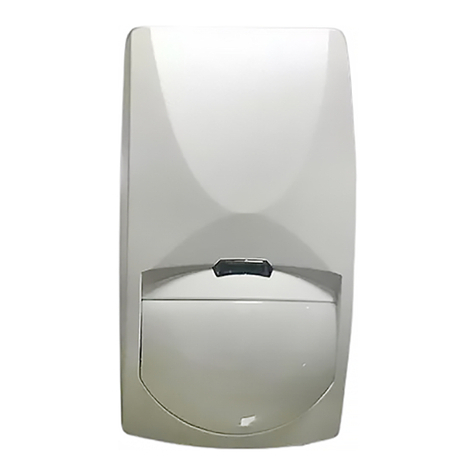
Mount the PIR
Location Dos:
• Place on a rigid, vibration-free surface.
• Place so intruder movement is across the detection pattern.
Location Don’ts:
• Don’t place on a surface with moisture exposure.
• Don’t place in any area containing excessive metallic surfaces.
• Don’t place where the PIR may be exposed to false alarm sources such
as direct sunlight, heat sources (heater, radiators, etc.) or in the eld
of view or strong air drafts (fans, air conditioner, etc.)
Use the following steps and Figures 3 and 4 to mount the PIR:
1. Touch grounded metal to discharge static before handling the PCB.
2. Remove the PCB from the base to expose the mounting holes.
Grasp the unit and push on the battery case, gently sliding the PCB
toward the top of the base. Lift the PCB out of the housing.
3. Select the appropriate mounting holes on the base for either corner or at
wall mounting.
4. With the cover lock screw hole facing down, attach the base to the wall using
screws and wall anchors. Do not over-tighten the screws.
5. Replace and secure the PCB back in the base.
6. Place the cover on the base and secure it with the cover lock screw, restoring
the tamper.
Test the PIR
Wireless Walk Test
Use a Wireless Walk Test to conrm that the PIR is communicating with the panel.
Enter 8144 and then CMD for XR150INT/XR550INT Series panels or 814 and then
CMD for XT30INT Series panels. Select WLS. If the 1126W-WINT fails to check in
with the panel, relocate the device or receiver and repeat the Walk Test.
PIR Walk Test
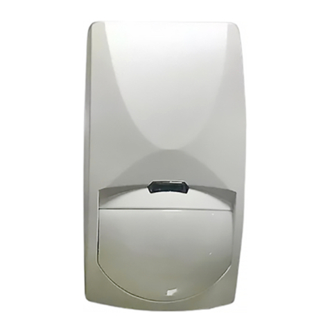
The PIR Walk Test allows you to verify proper placement of the 1127W-WINT. The LED is enabled for 30 minutes
allowing you the time to ensure proper detection patterns of the installed units. The LED will ash for each trip
of the 1127W-WINT. Any 1127W-WINT units that have Disarm/Disable set to YES are temporarily enabled when the
Walk Test begins. The Walk Test is a local test only and no results are sent to the Central Station.
Replace the Batteries
1. Remove the cover. See Figure 2.
2. Remove the old batteries.
3. Observe polarity and install the new batteries.
Sensor Reset to Clear LOBAT
If the battery needs to be replaced, a LOBAT message will display at the keypad. Once the battery is replaced, a
sensor reset is required at the system keypad to clear the LOBAT message. On a Thinline Keypad, press and hold
2for two seconds. On a Graphic Touchscreen Keypad, press RESET. Enter your user code if required. The keypad
displays SENSORS OFF followed by SENSORS ON. The 1127W-WINT remains operational for approximately 30 days
to allow adequate time to replace the battery.
Wall Mount holes
Corner Mount holes
Figure 3: Mounting Holes
Cover Lock Screw
Figure 3: PCB Removal
