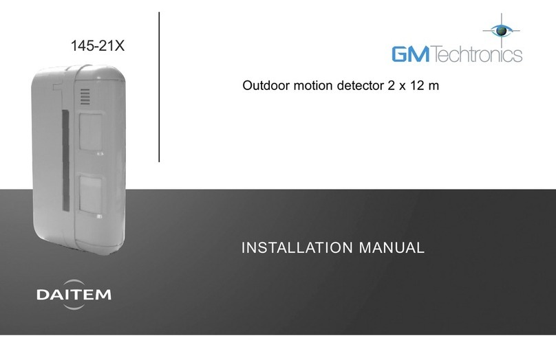
DAITEM 144-21X User manual

Upgraded for e-Nova applications

52
B
The special animal immune external movement detector monitors the inside or the
outside of buildings and distinguishes between humans and animals.
It is equipped with two sets of detection beams (higher and lower) which must be broken
simultaneously to activate a pre-alarm or a full alarm. Its detection range can be
adjusted, reducing false alarms due to unwanted detections (cars, people or animals
outside the desired protection area).
Description
Summary
1. Introduction ............................................... 52
2. Preparation ................................................ 53
2.1 Opening the detector............................ 53
2.2 Power supply ........................................ 53
3. Programming............................................. 54
4. Configuration............................................. 55
5. Installation precautions............................ 55
6. Installation.................................................. 56
6.1 Testing the radio link............................. 56
6.2 Wall fixing.............................................. 56
6.3 Pole fixing.............................................. 56
7. Configuration and adjustments
of detection................................................ 57
7.1 Range of detection ............................... 57
7.2 Horizontal orientation............................ 57
7.3 Mask a zone.......................................... 58
7.4 Adjustment of the sensitivity ................ 58
7.5 Adjustment of the operational
options .................................................. 58
8. Operating test............................................ 59
9. Maintenance.............................................. 60
9.1 Fault indication...................................... 60
9.2 Changing the battery............................ 60
10. Technical data ......................................... 61
1. Introduction
Detector module
Top pyro sensor
Bottom pyro sensor
Switch for sensitivity optionsDip-switch for operational
options
Range
detection
switch
Cover
Led
Indicator
Locking screw
Back box
Clamps
for
post
Screws
IMPORTANT
• Some functions are only available with control panel version 2.0.0 or later
(enter ) on the control panel keypad to check the version).
• Operating differences with respect to former ranges are described in the compatibility booklet
available in the Daitem Installers section at www.daitem.co.uk.
Recommendations
The user must not attempt to access the detector’s internal parts, except areas described in this manual. If the user does access these
parts, the product guarantee will be considered null and void and DAITEM shall not be held responsible for any problems. Touching
the detector’s internal parts and/or electronic components can damage the product. Furthermore, the detector is designed in such a
way that these parts and components do not need to be accessed for operation or maintenance purposes.
53
B
Connect the battery.
When switched on, the detector runs a self-test.
If the self-test is:
• correct, the LED indicator lamp lights up for 2 sec.,
• incorrect, the LED indicator lamp flashes every 5 sec.
d
d
.
.
2. Preparation
2.1 Opening the detector
2.2 Power supply
Detector module
Cover
Radio
board
Test key
Lithium battery
connector
Indicator lamp
for programming
Connector
for detection
module
Connecting
cables for
radio board
and detector
module
Lens support
Detection lens
Lithium
battery 1. Undo the screw with
a phillips screwdriver
and remove the
cover.
2. Unscrew the
detector module
fixing screw.
3. Remove the back
box.
Description (continued)
Guarantee sticker: remove the pre-
cut part of the sticker and stick it to
the guarantee certificate in the user
manual supplied with the control
panel. If you are adding to an existing
system, use the guarantee certificate
supplied with this product.
144-21X
A1142A047879
Coller sur certif
144-21X
A1142A047879
Coller sur certif

54
B
3. Pro rammin
IMPORTANT: the device does not need to be placed close to the control panel for recognition programming. In fact, we advise you to
move the product at least 2 metres away from the control panel.
This operation allows the control panel to recognise the detector.
2. Proceed as follows for recognition programming:
1. For detector recognition programming, the control panel must be in installation mode. If it is not, ask the user to enter:
then
IMPORTANT: the control panel issues three short beeps to indicate a programming error. When this happens, programming must
be performed again from the beginning.
Press *then #on
the control panel
keypad.
Press and hold the “test”
button until the control
panel responds.
Select the group from 1 to
8*. Use the control panel
keypad to do this.
Select the time delay:
0: immediate
1: delayed
2: combined
Use the control panel
keypad to do this.
The control panel
issues a voice
message to confirm
detector recognition
programming.
then to
)))))
10 s max.
“detector X” “group ?” “time delay?”
*to
* depending on the type
of control panel
master code (factory: 0000) installer code (factory: 1111)
“beep, detector X,
group Y, immediate
(or delayed
or combined)”
“beep, installation
mode”

55
B
In factory configuration, the movement detector is configured in
Deterrence (for the reactions of the system see the control panel
installation guide). It is possible to modify the level of alarm using
the following sequence of parameter setting:
Parameter n° Alarm level Parameter value
4 Intrusion 1
Prealarm 2
Deterrence 3 (factory setting)
Warning 4 (the feature is available using control panels
with 2.0.0 version software or later)
Sequence of
parameter setting
Indicator
lamp for
programming
not lit
Indicator
lamp for
programming lit
sequence
about
10 sec.
about
5 sec.
about
10 sec.
about
2 sec.
To st rt
the sequence
press nd hold
the button
until the LED
indicator lamp
goes out
Press 4 times
depending
on the required
parameter
number
Press nd
hold until
the LED
indicator
lamp
briefly
goes out
Press
1 to 4 times
depending
on the
required
parameter
value
To end
the sequence
press nd
hold the
button until
the LED
indicator
lamp goes
out
LED
indicator
lamp lit
=
correct
confi -
guration
Configuration example: setting the detector for an alarm level
when a prealarm is triggered: parameter n° 4, parameter value 2.
4 2 2 s.
env.
St rt Press 4 times
to select
the alarm
level
Press
once to
accept
selection
Press 2 times
to select
the prealarm
level
End
The motion detector must be placed:
The motion detector must not be placed:
Directly on to a metal wall or close to sources of interference
(electricity meters, etc.) or ventilation such as air-conditioning
grilles.
parallel
0.8 m < H < 1.2 m
With an installation height
from 0.8 to
1.2 m high.
Perpendicular to the ground, so that
the zone of higher detection is
parallel to the ground.
If the detector is tilted compared
to the ground, the reliability
of operation can be reduced.
4. Confi uration 5. Installation precautions
{
{
IMPORTANT: make sure there is a distance of at least 2 meters between
each product, except between two detectors.
parallel
In direction of moving objects
(branches, bushes, flags,
etc.).
In an area likely to receive
direct sunlight or a very
powerful light source.
By adjusting the zone of
detection so that the objects
or people moving “cross”
the zone of
detection.

56
B
1. Before fixing the detector, place them
close to the fixing point and check the
radio link with the control panel.
If the link with the control panel is
correct, the control panel issues a voice
message identifying the detector
activated.
2. Press (> 5 sec.) the “test” button on the
detector, the control panel issues the
following voice message: “beep, test,
detector X (customised message), group
Y, (immediate or delayed or combined)”.
1. To fix the back box on the wall using
wall plugs and suitable screws (not
provided).
Fastening screw
2. Connect the 2 cables of the
detection module onto the radio
board.
2. Fit the U clamps around the post
and screw the back box to the post
using the M4X30 screws provided.
3. Position the
detection
module on
the back
box then
tighten the
screws.
.
.
1. Fix the the support clamps on the
back box with the fastening screws.
Clamps
for
post
Post
Screws
3. Complete stages 2. and 3. as per
wall fixing.
6. Installation
IMPORTANT: the post must have a Ø from 43
to 48 mm.
IMPORTANT: it is imperative to connect the
power on the radio board before the 2 cables
of the detection module.
6.1 Testing the radio link 6.2 Wall fixing 6.3 Pole fixing
)))))
“beep, test detector X, group Y,
(immediate or delayed
or combined)”

57
B
The range of the lower beam determines
the range of the detector.
The higher beam remains always parallel
on the ground. The lower beam is
adjusted according to the position of the
switch as the figures show it below. Being
given that the beams (higher and lower)
must be broken simultaneously to set off
an alarm, the range of the detector is
limited to the range of the lower beam.
0 5 10 15
0 5 10 15
0 5 10 15
0 5 10 15
Height of installation 1 m
To adjust the range of detection, slide the
switch to the desired position.
Position A (12 m)
Position B (8 m)
Position C (5 m)
Position D (2 m)
Position Standard range Maximum range*
(m) (m)
A 12 10 - 15
B 8 6 - 10
C 5 4 - 5,5
D 2 1,5 - 2,5
* The maximum range can vary from the standard
values according to the environmental
conditions.
d
d
45 °
45 °
90 °
45° adjustable
45° adjustable
View from the top with the horizontal orientation
positioned on the middle notch
Be ms
of detection
Detection range switch
7. Confi uration and adjustments of detection
7.1 Range of detection 7.2 Horizontal orientation
Detection:
the lower nd higher be ms re broken
Range of detection
Range of detection
Range of detection
No detection:
only the lower be m is broken
No detection:
only the higher be m is broken
To adjust the area of detection, hold
the body of the detector
and direct it in the
direction desired
by 15° notch's.
The area of detection is of 90°
with 7 spaced beams of 15°.
The detector unit swivels to the right
or the left by
notch's of 15°.

58
B
This adjustment makes it possible to
adjust the sensitivity level of the detector.
For environmental conditions:
• difficult (wind, bad weather...), decrease
the sensitivity (position L),
• in a stable warm environment increase
the sensitivity (position H),
• standard sensitivity leave the switch in
position M.
The adjustment of the options is done by
3 DIP switches located inside the detector.
Operating
options DIP
switches
ON
Detector in TEST mode,
LED lights during each detection.
Detector in NORMAL mode,
LED remains off. The period
between radio transmissions
depends on the position of DIP
switch n° 2.
5 sec. battery saving timer
radio transmissions are limited to
a 5 second timer interval even
if multiple detections occur.
120 sec. battery saving timer
Radio transmissions are limited to
a 120 second timer interval even
if multiple detections occur.
Position recommended in the
event of frequent passage inside
the zone of detection.
2 - Pulse count
detection if 2 beams are broken.
4 - Pulse count
detection if 4 beams are broken.
ON
ON
ON
ON
ON
Zone mask
7.3 Mask a zone 7.5 Adjustment of the operational options
7.4 Adjustment of the sensitivity
IMPORTANT: as previously indicated (see “ orizontal orientation”), the zone of detection always
includes 7 detection beams. If you modified the horizontal orientation angle and thus the zone of
detection, check the positioning of these beams before setting up the zone mask.
To reduce the beams, adjust the lens with the zone mask provided.
Sensitivity
selector switch
(L, , H)
1. Separate the support from lens and
the cover as indicated.
2. Separate the lens from the cover.
Position the zone mask provided
inside the lens, in order to mask the
unwanted detection zone.
3. Replace the lens by aligning the 4
pins of the cover into the 4 notches of
the lens. Make sure that the lens is
correctly vertically orientated during
the installation.
4. Position the lens support back in
place. Check that the lens support is
well secured on each side by the tabs
of the cover.

59
B
1. Switch the control panel to user mode:
2. Put your control panel in Total Arm mode.
3. Wait for the exit time delay.
4. Cross over the protected area and
check that the control panel responds
(see your control panel’s installation
manual).
IMPORTANT
• According to environmental temperature conditions, the zone of detection can vary from 1.5 to 2 m.
Example: If the range of detection is set in position A (12 m),
it is possible that the vehicle is detected, according to ambient
temperature conditions.
- In this case, set the range on the detector to position B,
the range will be 8 m, which is shorter than the ideal
range but can reduce the risk of unwanted detections.
- Confirm by a test the operation.
There must be detection in zone (a) and not in zone (b).
• The detector has a multi-level pattern of detection
(side view). A heat source located beyond the zone
of detection can cause a false alarm by reflection
on the ground.
Examples of reflective grounds: water (puddles, pools),
wet roads, smooth surface, concrete & asphalt, etc.
Reflection rate is not 100% of course on the ground, however,
if the heat source is strong and / or reflection rate is high, detection distance will be longer
than required and may detect unwanted objects beyond. Select the detection ground
position, according to the ground condition of the installation site.
Approximately
12 m
Position A
Approximately
8 m
Position B
Approximately
13 m
Approximately
8 m
Approximately
12 m
Position B
(a) (b)
3. Switch the control panel to test mode:
4. Check the area of detection using the
indicator LED and adjust the detector if
need be. With each detection the
control panel issues the voice message
“Beep, deterrence detector X”
(depending on the configuration).
5. Switch the control panel back to
installation mode, press:
6. Reopen the cover, to put DIP switch 1 to
OFF, then refit the detector cover.
8. Operatin test
8.1 Detection zone test
8.2 Real test
engineer installer code
1. Put DIP switch 1 in the ON position.
2. Close the
detector cover
and tighten
the locking
screw.

60
B
The control panel takes battery faults, anti-tamper faults and
radio faults on the detector into account.
• Battery fault: following a system command, the control panel
issues the following voice message:
• Anti-tamper fault: following a system command, the control
panel issues the following voice message:
• Radio fault: following a system command, the control panel
issues the following voice message:
“beep, fault, battery, detector X”
“beep, fault, anti-tamper, detector X”
“beep, fault, radio, detector X”
1. Switch the control panel to installation mode and ask the
master user to press:
then press:
2. Open the case of the detector (see § Opening).
3. Disconnect the cables from the detection module to the radio
board.
4. Replace the used lithium batery.
5. Reconnect the cables from the detection module to the radio
board.
6. Close the case of the detector.
7. Switch the control panel back to user mode, press:
9. Maintenance
9.1 Fault indication 9.2 Changing the battery
master code
engineer installer code
• The lithium battery pack must be replaced by the same type of pack with
the same technical characteristics, i.e. (3.6 V - 4 Ah).
• We advise you to use the DAITEM BatLi05 pack available
in the catalogue in order to guarantee individual safety
and equipment reliability.
• Dispose of the waste lithium power pack in an appropriate
recycling bin.
Li
IMPORTANT: the detector’s configuration is saved when the battery is
changed.
IMPORTANT: the test button makes it possible to check if the battery is OK.
The indicator on the radio board lights red when the button is pressed.
engineer installer code

61
B
Specifications Special animal immune external detector
Detection infrared
Coverage adjustable from 2 to 12 m-90°
Use inside/outside
Power supply 3.6 V - 4 Ah BatLi05 lithium battery
Battery life 5 years in normal conditions of use
Radio links TwinBand®400/800 MHz
Fixing methods • wall
• pole
Operating temperature - 20°C a + 50°C
Degrees of mechanical protection IP 54
Anti-tamper protection against opening
Dimensions L x W x H 80 x 198 x 108
Weight 560 g
Acessories clamps for posts, screws, zone mask
Non-contractual document, may be modified without prior notice.
Waste processing of electrical and electronic devices at the end of their service
life (Applicable in European Union countries and other European countries with a
waste collection system). Used on products or product packaging, this symbol indi-
cates that the product must not be thrown out with household waste. It must be taken to a
waste collection point for electrical and electronic product recycling. When you make sure
that this product is disposed of in the most appropriate manner, you are helping to protect
the environment and human health. If you would like additional information concerning the
recycling of this product, please contact your town/city council, nearest waste collection
centre or the shop where you bought the product.
10. Technical data
DECLARATION OF CONFORMITY
Manufacturer: ager Security SAS
Address: F-38926 Crolles Cedex - France
Product type: Special animal immune external detector
Trade mark: Daitem
We declare under our sole responsibility that the product to which this declaration
relates is compliant with the essential requirements of the following directives:
• R&TTE Directive: 99/5/EEC
• Low voltage directive: 2006/95/EC
• Directive RO S: 2002/95/EC
in compliance with the following harmonised European standards:
This product can be used in all EU, EEA Countries and Switzerland.
Crolles, 01.04.2013 Signature:
Patrick Bernard
Director of Research and Development
Products code 144-21X
EN 300 220-2 V2.1.2 X
EN 300 330-2 V1.3.1
EN 50130-4 (95) + A1 (98) + A2 (2002) X
EN 55022 & 55024 (2002)
EN 60950 (2006) X
EN 301 489-1 V1.8.1 X
13
B

62

63

805424/A - 04.2013
Table of contents
Other DAITEM Security Sensor manuals

DAITEM
DAITEM 173-21X User manual

DAITEM
DAITEM 171-21X User manual

DAITEM
DAITEM SH195AX User manual

DAITEM
DAITEM SH273AX User manual

DAITEM
DAITEM SH271AX User manual

DAITEM
DAITEM DP1101 User manual

DAITEM
DAITEM SH101AX User manual

DAITEM
DAITEM 145-21X User manual

DAITEM
DAITEM DP1201 User manual

DAITEM
DAITEM 191-21X User manual
Popular Security Sensor manuals by other brands

B.E.G.
B.E.G. LUXOMAT PD9-M-2C Installation and operating instruction

STEINEL
STEINEL US Quattro COM1-24 user manual

Bosch
Bosch MS-LZS installation manual

Hokuyo
Hokuyo UGM-50LXP manual

ST Quadrat
ST Quadrat LUX-top QUICKFIX II Installation and user instructions

Industriarmatur
Industriarmatur SIPP Node 400 installation instructions