DNS AS-410 User manual

- 1 -
AS-410
Operation Manual
Auto Trimming Unit
2017/8/21
Ver. 1.00

2
Overview
This option enables the System to perform rough-cutting (trimming) while automatically monitoring the
exposure of the tissue on the sample block surface via a CCD camera under two LED lights (incident
and reflective). The System continues trimming until tissue is exposed for the predetermined tissue
exposure ratio (%). The photographed image is sent to the attached PC. The analysis processing and
judgment are done by automatic surface analysis software.
In order to use the Automatic Trimming Function, it is necessary to set up the conditions on the AS -
410 operation screen, the Trimming Setting screen, and the automatic surface analysis software. In
case of sectioning using this function, this setting is reflected in all the set blocks.
Incident LED light
CCD camera
Reflective LED light
Sample
Microtome blade Tissue
Paraffin-embedded tissue block (sample)

3
Device Configuration
Reflective Light
Auto Trimming Unit
photographing area
Diffused lighting
CCD camera

4
1.How to set
1-1.Setting on AS-410
Auto Surface Detection application detects the sample surface by following procedure.
①Apply Surface Cut (rough cut) to eliminate unevenness of the block surface.
②From the top surface of the block, the area of the block surface and the tissue image were taken.
Analyze and calculate the maximum tissue embedding area from the image.
③Initial trimming (roughing) is performed in order to expose the tissue surface to the block surface.
④Reflected light illuminates the surface. Tissue image exposed on the surface is photographed, and
the tissue surface is analyzed from the image and calculated.
⑤With the calculated maximum tissue embedding area as 100, the proportion of the tissue surface
exposed on the surface calculated in ④is displayed as the surface detection rate (%). The
measurement result is equal to or higher than the preferred set surface detection rate after the
roughing, sample preparation operation starts. If the exposed area ratio did not reach to the set
surface detection rate, the system repeats the rough cutting and measuring.
Note
・Tilting mechanism does not work with the Auto Trimming function.
・Samples in following conditions are not suitable for Auto Trimming function.
1. Color of the tissue specimen similar to the color of paraffin or paraffin
casette.
2. Tissue surface is not parallel to paraffin surface.
3. Embedded tissue thickness is less than 5mm.
4. Multiple tissues are embedded at different depth in single paraffin block.
5. Large gap between the tissue size observed from upper side and surfaced
tissue size. Exmaple: tube form
①
Surface Cutting
②
Capturing the
whole tissue image
③
Initial Trimming
④
Surfaced
area
⑤ Calculate the surface
detection rate (%).

5
1-1-1.Setting the Main Body
Set the conditions for the Auto Trimming function using the operation panel of the main
unit.
Setting Auto Trimming
Chose “MAINTENANCE” on the MAIN MENU screen.
①Chose “AUTO TRIMMING” on the MAINTENANCE screen.
When Auto trimming setting screen appears, enter the values referring to the Table 1.
MAINTENANCE screen
MAIN MENU screen
AUTO TRIM SETTING screen
Note
・Set the amount which eliminates unevenness for the Surface Cut amount.
・Make the initial setting for the Initial Trimming 100µm to start sectioning operation first. Confirm
the Auto Trimming condition and apply adjustment when necessary.
・Fort the Max. Vol, make the initial setting 500µm to start sectioning and confirm the
condition of the Auto Trimming, and apply adjustments if necessary.
・Make the initial setting value 70% and confirm the condition after the Auto Trimming, apply
adjustments if necessary.
表面カット量については、表面に凹凸が無くなる厚さを設定してください。

6
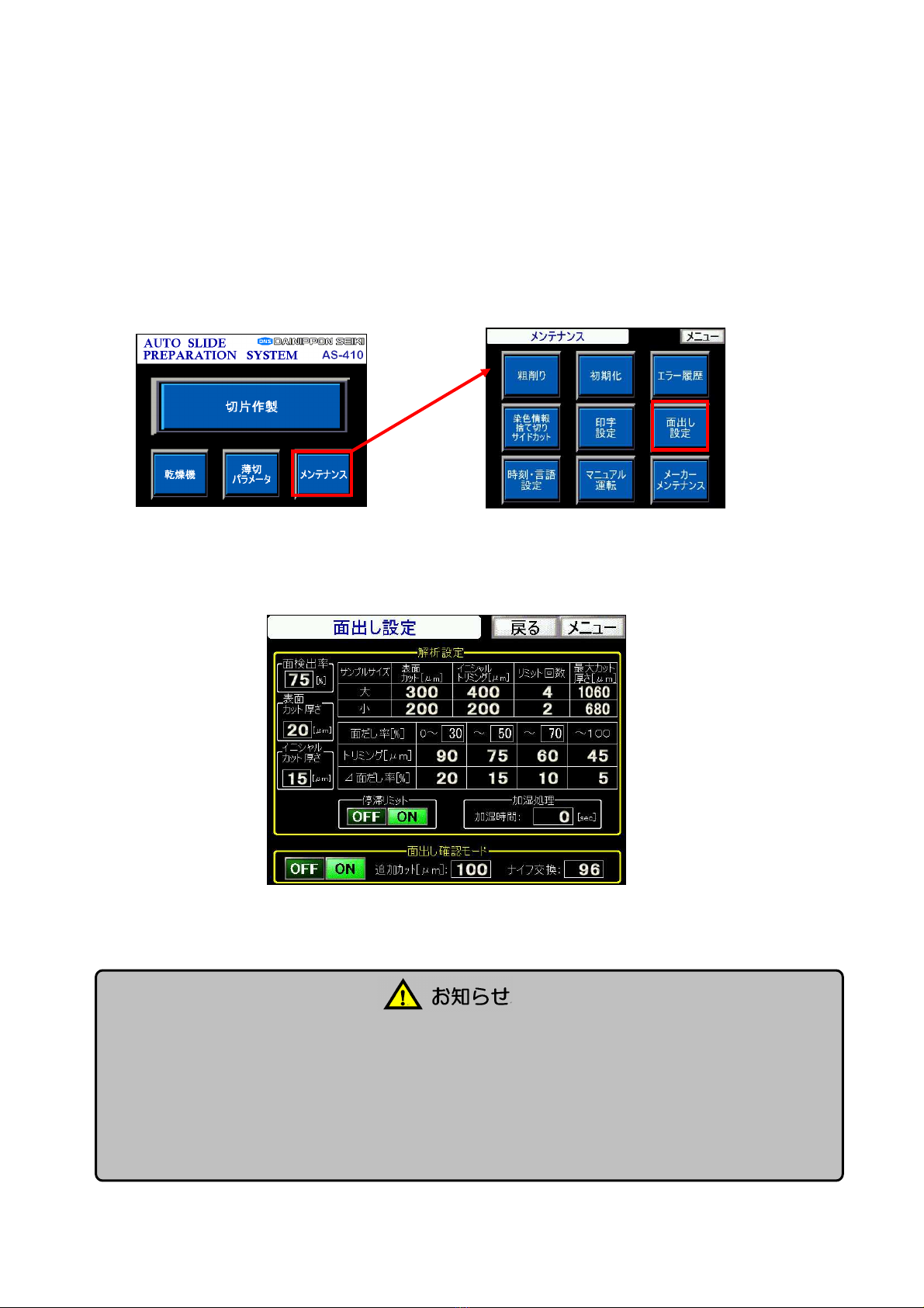
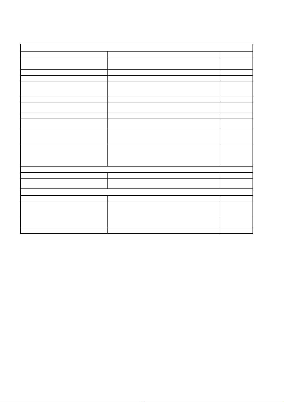
Chart 1. Auto Trimming Setting items
Basic auto trimming setting
On-screen item Description
Setting range
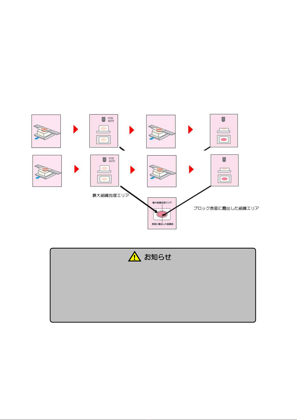
Surface detection ratio (Threshold)
(%)
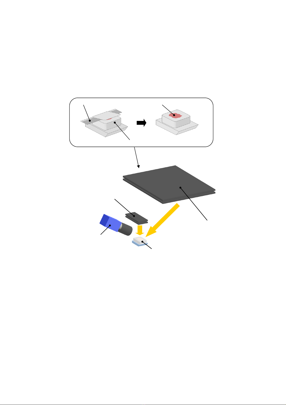
Size of tissue specimen on paraffin surface compare to
the entire tissue size. 1 to 99
1st Thickness
Thickness of 1st surface trimming per single slicing.
3 to 30
2nd Thickness
Thickness of 2nd initial trimming per single slicing.
3 to 30
Sample Size
Sample block surface size
Reguler: 24x37mm to 16x16mm Small :15x15mm to
under
―
Surface trimming (1st trimming) (μm)
Amount of rough-cut before detecting entire tissue size. 0 to 999
Initial trimming (2nd trimming) (μm)
Amount of rough cut before detecting tissue size on
paraffin surface.
1 to 999
Retry count
Maximum number of the retry-trimming.
1 to 99
Maximum volume (thickness)
Max. limit of thickness of rough-cut during auto trimming
function.
―
Wait limit
In case of failing to reach threshold after auto trimming,
the machine will:
On: make tissue slides Off: skip slide sectioning
―
Trimming rate (%) The amount of additional trimming (rough-cut) if the
surface detection ratio does not exceeded the
threshold.
The rough-cut volume is determined by the
increased volume (δ Threshold).
1 to 99
1 to 999
- 99 to 99
Humidification treatment
On-screen item Description
Setting range
Humidifying time
Length of humidification before measuring the tissue size
on paraffin surface.
0 to 999
Auto trimming manual check mode
On-screen item Description
Setting range
ON,OFF
ON: Apply Auto Trimming to all sample blocks first,
check, then start sectioning of the blocks. OFF: Apply
Auto Trimming and sectioning to each block one by one.
Add trimming (μm)
Amount of additional trimming after checking the image
on Auto Trimming screen. 0 to 999
Blade Change
Number of blocks to apply Auto Trimming per blade

7
1-2.Setting the Auto Trimming Analysis Software
1-2-1.How to install the Auto Trimming Analysis software
(1) Open the AsScan_9 folder.
(2)Click
(3)Press Next (N) when the AsScan setup wizard appears.
(4)Choose the folder to install the software then
click next.
(5)Click Next on the installation conformation screen
when appeared.
。
(6)Click Close when the installation completion screen
appered.
(7)Open the installed folder(\KURABO\AsScan), copy
BASEIMAGE、BASEIMAGED, and BASEIMAGER from
The AsScan_9 folder.
(8) Right click on the AsScan icon, choose Properties,
and check on “Run this program as an administrator.”

8
1-2-2.Setting device
1)Click “AsScan”icon on the desktop.
2)Check if Auto-Trimming analysis software opens normally.
3)Press “Abort” on the main menu of the analysis software.
4)Press the Save Directory button(①) and choose where to
save the examination images. (ex:C:\AS-400\work)
5)Press Parameter Setting button(②).
6)Enter the Password (71953).
7)Set the examination setting parameter referring
to the list below dingly to the list below.
Item1 Item 2 Value
Examination
Area
(Entire area)
GAIN
Gain 350
White Balance B 43
White Balance R
56
Tissue area
(Tissue Size)
GAIN
Gain 277
White Balance B 43
White Balance R
56
Surface Area
(Tissue Surface)
GAIN
Gain 300
White Balance B Auto
Test
(Test)
GAIN
Gain 350
White Balance B Auto
Fig.2 main menu (PC)
Fig.1 Password input screen
Fig.3 Parameter setting Screen
①
②

9
8)Press Device button
Check the below listed items.
① If [Serial Number] is consistent with the Serial
Number with camera.
② If [Video Format] is BY8(640×480 VGA).
③ If Frame Rate(FPS) is set with “30.0003.”
9)Press ‟Properties.”
10)Check the settings for Color, Exposure, and Image.
① Color
② Exposure
③ Image
11)Check the settings and press
[Update]→[OK] to finish.
Hue
180
Saturation 128
White Balance Red 56
White Balance Blue 43
Brightness
0
Saturation
300
Exposure
1/16 sec
Auto Reference
128
Auto Max Value
Auto
Image
100
Fig. 4 Device Setting screen
Fig. 5 Device Setting screen (color)
Fig. 6 Device Setting screen (Exposure)
Fig. 7 Device Setting screen (Image)

10
1-2-3.3.Shooting position and light quantity adjustment
1)Set the block for adjustment in the device.
2)On the main unit operation panel, press “Main Menu”
→“Maintenance”→“Maker Maintenance”and input
password, press“Device
Setting,”and confirm that the Auto-Trimming is “ON.”
3)On the main unit operation panel, press “Main Menu”
→“Maintenance”→”Manual Operation” → “Sample
Feeding” and place the block for adjustment on
the Sample Stage.
4)Chose“Manual Operation”“Sample Holder”to detect the level then detect the height.
Move the right and left axis (X) position to the surface detection position as well as the
up and down axis (Z).
5)Press LIVE button on the Menu screen.
6)Adjust the camera up & down and right & left position as viewing the screen.
7)Choose “Manual Operation” →”Auto-trimming” to move the reflected illumination to the
right and turn ON the light. Make certain to turn OFF the internal light for the device
(switch located on the front door).
8)Press the blue circles to check the amount of
light at the upper 2 points and the lower 2 points
and the central point on the block.
9)Adjust the aperture of the camera if amount
of detected blue light at the five points is not
between 90 ~110.
If there is a significant irregularity of lights,
check the position of the illumination position and
angle.
10) Start the Parameter Setting on PC and
press camera test “Reflected” button.
Fig.9 main menu PC (2)
Fig.11 main menu PC (1)
Fig.10 main menu PC (3)

11
11. The correct
light quantity within the range is displayed as shown below. TissuePlane
is a place where it is recognized as the surface of the block that is displayed in white.
Check if the system recognizes the same area with the block surface as shown in A.
If it is displayed like B, measure the amount of light on the surface of the block again
and check whether there is no variation in the amount of light or whether the light is
not strong or weak. (See ① to ⑤)
①It recognizes wider than the actual block surface.
→Adjust the aperture for increasing the darkness.
②The block surface is not recognized. → Turn
the aperture of the camera to make it bright.
③Only the upper side (or the lower side) is bright (A).
When the position of the reflected illumination is bright
only on the upper side, move it in the backward direction.
If only the lower side is bright, move it forward.
④Only the right side (or the left side) is bright (B)
Adjust the right movement stop position of the reflected
illumination. When only the right side is bright, set the stop
position to the left side, and when only the left side is bright,
set the stop position to the right side.
* Adjust the camera aperture after correcting the illumination
position.
* Refer to P2 for the method of correcting the lighting position. C
Fig.11 Parameter setting Screen
A B
A
B

12
⑤ Part of the block surface is chipped (C)
Check if there is anything making a shadow between
the lighting and the block surface, and if light intensity is not low.
1-2-4. Confirmation with tissue block
1. Shave the surface of the block to eliminate unevenness.
2. From the main unit operation screen, press "Main Menu"
→ "Maintenance" → "Manual Operation" → "Sample
Supply", and place a roughed block (at step 1) on the
sample stage with “sample feeding.”
3. Go to "Manual Operation" then "Sample Holder" and
perform
horizontal detection → height detection. Move the left
and right (X axis) position to the surface detection point
as well as the upper and lower (Z) position.
4. Press the Abort button on the Auto-Trimming software
menu.
5.Go to “Main Menu”→“Maintenance”→“Manual Operation”
→open ”Roughing”
6.Choose “ON” and “Right” for the reflected illumination on
the screen.
7. Press Entire area button (①) on the Auto-Trimming
software to check if the block surface is accurately
determined.
8.On the main unit Auto-Trimming screen, set the reflected
illumination light
OFF and turn the diffused illumination light On.
9.With the Auto-Trimming software, press "Tissue area
button (②) and confirm if the embedded tissue area in
the block is captured accurately.
10.Trim the block surface again until the trimmed tissue
appears on the block surface.
11.Press the Tissue Surface button (③) under the Auto-Trimming software.
12.Confirm whether it accurately captures the tissue area.
13.If the analysis result is not satisfactory, press the Parameter setting button (④) with
the Auto-Trimming software.
①
②
③
④
①

13
1.Tissue Size
Detection Level ⑤
The threshold for determining the embedded tissue area.
The threshold can be set within the range of 0 to 255.
If the system recognizes the tissue area too wide, then lower
the value. If the system recognizes the area too narrow, raise
the numerical value.
Tissue Surface
Surface⑥:Detects tissue from the area recognized non-tissue area of the exposed
surface.
· Calculate the acceptance value for the paraffin color in the non-tissue area from the block surface
contour 6 pt. Determine the percentage to consider as paraffin, then set the threshold for the
acceptance value. A value to decide what percentage of the judgment value to use for paraffin. Use
level to adjust judgment value.
Boundary⑦:
A threshold for judging whether each roughly detected exposed surface (label) is paraffin
or a tissue
・Automatically calculate acceptamce value for each chunk.
・Determine whether it is a tissue surface or a paraffin surface by judging the blue color of a clump,
uniformity of tissue, and brightness.
・Set the acceptance value threshold. 。
The larger value enlarges the area determined as tissue.
1
255
0
200
⑤
⑥
⑦

14
2-1 How to operate the Auto Trimming function
2-1-1
Starting the Auto Trimming application
To use the auto trimming function, the Auto Trimming Application (automatic measurement) must be
started before starting the Section Operation mode. Follow the steps below to start the application:
①Turn ON the PC and start the software.
②Choose On for the Auto Trimming and set the surface detection rate (threshold).
③Press “START.”
④ If “SAMPLE MONITOR MODE” is
“ON,” the index screen will appear after
the completion of the trimming of all the set blocks.
Slide Preparation screen
Auto Trim Setting screen
SLIDE PREPARATION

15
⑤ Click the tissue surface image on the
INDEX screen. The image will be enlarged.
⑥Check on the ones which need additional
trimming.
⑦Clicking the “Add trimming” starts the
additional trimming.
⑧Check on the ones to section.
⑨Clicking on “Slide Preparation” starts the
sectioning operation.
Finishing the Auto Trimming Application
Finish the Application following the below steps.
① Click the “ “ on the upper right corner of the application screen.
②Then click the Exit button for the Blade Mark Check application. The Auto Trimming
Application will be turned off.
③Shut down the OS for the PC.
INDEX screen
Table of contents
Other DNS Industrial Equipment manuals
Popular Industrial Equipment manuals by other brands

Parker
Parker F11 series Service spare parts list

Buhler
Buhler SDW 800/1000 operating instructions

HEIDELBERG
HEIDELBERG DryStar 2000 instruction manual

Neptune
Neptune G-50-1 Operating instructions manual

STAUFF
STAUFF RH Series Translation of the original operating instructions

Prozone
Prozone PZ2-1 Installation guide and operation manual