Doepke Dupline DSS 4R User manual

3931176/08/12/D
Doepke
Dupline
Tastsignalsensoren DSS 4R/DSS 4R-EIB
mit Rückmeldung
DSS 4R/DSS 4R-EIB Operating Signal Sensors
with Acknowledgement Feature
Bedienungsanleitung
Operating Instructions

Sollten Sie Fragen zu diesem Produkt oder
zum Dupline-System haben, wenden Sie
sich bitte an:
In case of queries concerning this pro-
duct or the Dupline system please
contact:
Doepke
Schaltgeräte GmbH & Co. KG
Stellmacherstraße 11
D-26506 Norden, Germany
Tel.: +49 (0) 4931/1806-0
Fax: +49 (0) 4931/1806-101 E-mail:
Internet: info@doepke.de
http://www.doepke.de
23931176/08/12/D - Technische Änderungen vorbehalten!
Doepke
Inhaltsverzeichnis
1. Allgemeines ......................................................................................................... 3
2. Kodierung............................................................................................................. 3
3. Inbetriebnahme.................................................................................................... 4
3.1. Allgemein ..................................................................................................... 4
3.2. Anschluss von Tastschaltern an den DSS 4R .............................................4
3.3. Anschluss von Tastschaltern an den DSS 4R-EIB ...................................... 5
4. Garantie ................................................................................................................ 5
5. Technische Daten................................................................................................ 5
Table of Contents
6. General Information ............................................................................................ 7
7. Coding .................................................................................................................. 7
8. Putting into Service............................................................................................. 8
8.1. General Information ..................................................................................... 8
8.2. Connection of Push-buttons to DSS 4R.......................................................8
8.3. Connection of EIB Push-buttons to DSS 4R-EIB.........................................9
9. Guarantee............................................................................................................. 9
10. Technical Data ..................................................................................................... 9
11. Anschlussschema / Connection Diagram.......................................................11
11.1. DSS 4R ...................................................................................................... 11
11.2. DSS 4R-EIB ............................................................................................... 12

3931176/08/12/D - Technische Änderungen vorbehalten! 3
Doepke
Deutsch
1Inhaltsverzeichnis
Bedienungsanleitung
Tastsignalsensoren DSS 4R/DSS 4R-EIB
1. Allgemeines
Die Tastsignalsensoren DSS 4R und DSS 4R-EIB sind Komponenten des Dupline In-
stallationssystems und ermöglichen die Einbindung von Standard- und EIB-Tastern mit
Rückmeldung. Sie verfügen über 4 Eingangskanäle und 2 Rückmeldekanäle mit der
zusätzlichen Möglichkeit, den Buszustand anzuzeigen (BUS-OK-LED). Durch ihre Bau-
form passen die Tastsignalsensoren hinter einen Installationstaster in eine normale UP-
Schalterdose.
Herkömmliche Taster und potenzialfreie Schaltkontakte werden am DSS 4R betrieben;
dies geschieht über zwei beigelegte, 4-adrige und mit Aderendhülsen versehene Sys-
temkabel. Dabei verhindert eine interne Tastsignalverlängerung Mehrfachschaltungen
durch mögliches Tasterprellen.
Die 24 V-Rückmeldeausgänge des DSS 4R sind jeweils mit max. 80 mA (2 W) belast-
bar. Grundsätzlich können beliebige Leuchtmittel verwendet werden; beim Einsatz von
Glühlampen darf der Einschaltstrom die maximale Belastbarkeit jedoch nicht über-
schreiten. Deshalb - und wegen der längeren Lebensdauer - empfehlen wir den Einsatz
von LEDs.
EIB-fähige 2-fach-Taster der Firmen Berker, Gira, Jung und Siemens können mit Hilfe
des DSS 4R-EIB am Dupline-Bus betrieben werden. Die beigelegte flexible Leiterplatte
mit Systemsteckern ermöglicht eine einfach herzustellende Verbindung.
2. Kodierung
Mit dem Handkodiergerät DHK 1 kann über die seitlich angebrachte Stiftleiste der Sig-
nalsensoren jedem Kanal jede beliebige Adresse zwischen A1 und P8 zugeordnet wer-
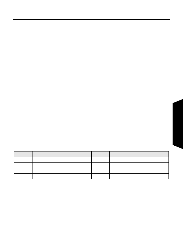
den. Die Aufteilung der Kanäle ist wie folgt:
Kanäle, die nicht benötigt werden, sollten unkodiert bleiben. Die Kodierung des Sen-
sors kann ohne Versorgungsspannung oder Dupline-Signal vorgenommen werden und
erfolgt mithilfe des Flachstecker-Kodierkabel DKP 2. Auf richtige Polarität des Kodier-
kabels ist zu achten, eine Verpolung führt aber nicht zur Zerstörung. Die Kodierung
bleibt dauerhaft erhalten, kann aber jederzeit überschrieben werden.
Kanal Beschreibung Kanal Beschreibung
1 Eingang Tastsignal 1 (T1) 5 Rückmeldekanal 1 (LED1)
2 Eingang Tastsignal 2 (T2) 6 Rückmeldekanal 2 (LED2)
3 Eingang Tastsignal 3 (T3) 7 Nicht belegt
4 Eingang Tastsignal 4 (T4) 8 Nicht belegt

43931176/08/12/D - Technische Änderungen vorbehalten!
Doepke
Deutsch
3. Inbetriebnahme
3.1. Allgemein
Die Installation darf nur von einer autorisierten Fachkraft vorgenommen werden. Bei
der Installation ist das Anschlussschema zu beachten. Alle anzuschließenden Leitun-
gen müssen spannungsfrei sein.
Sowohl das Dupline-Signal als auch die 24 VDC-Spannungsversorgung sind bei beiden
Tastsignalsensoren separat anzuschließen. Verbindungen zwischen dem Dupline-Sig-
nal und dem Erdpotenzial führen zu Störungen und sind nicht zulässig. Zudem ist auf
die richtige Polarität des Dupline-Signals zu achten.
Der Anschluss an den Dupline-Bus und an die 24 VDC-Versorgungsspannung ge-
schieht wahlweise über die beigelegten Feder- oder Schraubklemmen. Folgende Ta-
belle zeigt die Anschlussbelegung:
Um Störungen zu vermeiden, darf die Länge der Leitung zwischen Taster und den Sen-
soren bei normalen Umgebungsbedingungen 1 m nicht überschreiten.
Um den Forderungen für Schutzkleinspannung zu genügen, ist bei der Installation die
VDE0100, Teil 410, zu beachten und anzuwenden. Netzkabel dürfen aus Sicherheits-
und Platzgründen nicht durch dieselbe Schalterdose geführt werden (z.B. in Schalter /
Steckdosenkombinationen).
3.2. Anschluss von Tastschaltern an den DSS 4R
Die beigelegten 4-adrigen Systemkabel erlauben den Anschluss des Standardtasters.
Dabei ist darauf zu achten, dass die rote 24 VDC-Leitung des ersten Kabelsatzes nach
aussen zeigt. Die folgende Tabelle zeigt die Belegung der Anschlussleitungen:
Das Anschlussdiagramm finden Sie im Kapitel 11.1 auf Seite 11.
Klemme Beschreibung Klemme Beschreibung
D+ Dupline Signalleiter + 24 VDC Betriebsspannung +24 VDC
D- Dupline Signalleiter - 0 VDC Betriebsspannung 0 VDC
Pin Farbe Signal
Kabelsatz
1
1rot +24VDC
2 blau Kathode LED1
3 gelb Eingang Tastsignal T1
4 grün Eingang Tastsignal T2
Kabelsatz
2
1 grün-schwarz Eingang Tastsignal T4
2 gelb-schwarz Eingang Tastsignal T3
7 blau-schwarz Kathode LED2
8 grau Kathode BUS-OK-LED

3931176/08/12/D - Technische Änderungen vorbehalten! 5
Doepke
Deutsch
3.3. Anschluss von Tastschaltern an den DSS 4R-EIB
Die Verbindung zwischen dem DSS 4R und einem 2-fach EIB-Taster erfolgt über die
10-adrige, beigelegte flexible Leiterplatte mit Systemsteckern und der beigelegten Mon-
tageplatte. Legen Sie dazu den DSS 4R mit angeschlossener Dupline-Leitung, Span-
nungsversorgung und Systemkabel in die UP-Dose, führen Sie das Systemkabel wie
untenstehend angedeutet durch die Montageplatte und schließen Sie den EIB-Taster
an. Der EIB-Taster kann nach Festschrauben der Montageplatte in diese eingerastet
werden. Das Anschlussschema für den DSS 4R-EIB finden Sie in Kapitel 11.2 auf
Seite 12.
4. Garantie
Für fachgerecht montierte, unveränderte Geräte gewähren wir ab Kauf durch den End-
verbraucher die gesetzliche Gewährleistungsfrist. Die Garantie bezieht sich nicht auf
Transportschäden sowie Schäden, die durch Kurzschluss oder Überlastung entstanden
sind. Bei Fertigungs- und Materialfehlern, die innerhalb der Gewährleistungsfrist er-
kannt werden, leistet unser Werk kostenlosen Ersatz. Bei Öffnen der Messkammer er-
lischt der Garantieanspruch.
5. Technische Daten
Min. Typ. Max.
Dupline Stromaufnahme 750 µA
Eingangskanäle 4 Tastsignaleingänge
Ausgangskanäle 2 Rückmeldekanäle
Eingänge Art Halbleitereingänge
Spannung 21,5 VDC 24 VDC 26,5 VDC
Stromaufnahme entfällt
EIB-Montageplatte
EIB-Taster
Dupline-Bus /
Spannungs-
versorgung
Systemkabel

63931176/08/12/D - Technische Änderungen vorbehalten!
Doepke
Deutsch
Kontaktbelastung 1 mA
Erlaubter
Kontaktinnenwiderstand 1 kOhm
Leitungslänge 1 m
Ausgänge (Rückmeldung)Art Transistor-Halbleiterausgänge, 24 VDC open collector
Belastbarkeit / Ausgang 2 W (80 mA)
Betriebsspannung
Nennbetriebsspannung 21,5 VDC 24 VDC 26,5 VDC
Eigenstromaufnahme 9,8 mA
Anschlüsse DSS 4R
Klemmen
(montiert)
Art 2-polige Federkraftklemmen mit doppelten Anschluss-
punkten für Bussignal und Spannungsversorgung
Klemmbereich 0,4 mm ∅0,8 mm ∅
Klemmen
(beigepackt)
Art Schraubklemme mit Drahtschutz für Bussignal und
Spannungsversorgung
Klemmbereich 0,4 mm ∅1,5 mm²
Kabelsatz
(DSS 4R) Art 2 x 4 Leitungen LiYv mit Aderendhülsen
Klemmbereich 0,25 mm²
Kabelsatz
(DSS 4R-EIB) Art Flexible Leiterplatte, 10-polig mit Systemstecker
Klemmbereich -
Gehäuse Art Schalterdosen-Einbaugehäuse
Maße ∅50 mm x 10 mm
Material Polyamid, glasfaserverstärkt
Allgemeine technische Daten
Umgebungstemperatur -10°C +45°C
Luftfeuchtigkeit Max. 85% (Betauung nicht zulässig)
Schutzart / Normen IEC60669, EN55022 / EN50081-1 und EN55024 /
EN50082-1
Zubehör (DSS 4R-EIB) UP-Dosen-Montageplatte für EIB-Tastschalter
Bestellnummer, -bezeichnung 09 501 154, Tastsignalsensor DSS 4R
09 501 124, Tastsignalsensor DSS 4R-EIB
Min. Typ. Max.

3931176/08/12/D - The right to make technical changes reserved! 7
Doepke
English
1Table of Contents
Operating Instructions
DSS 4R/DSS 4R-EIB Operating Signal Sensors
6. General Information
The DSS 4R and DSS 4R-EIB operating signal sensors are components of the Dupline
installation system and enable conventional and EIB push-buttons to be linked to the
system. They are provided with 4 input and 2 acknowledge channels and, in addition,
offer the possibility of indicating the bus status (BUS-OK LED). Because of their com-
pact design the operating signal sensors can be fitted behind a push-button in a stand-
ard flush-mounted installation box.
Conventional push-buttons and potential-free switching contacts can be operated with
the DSS 4R via two 4-wire system cables supplied complete with end ferrules. An inter-
nal extended operating signal prevents any multiple switching occasioned by possible
contact bounce.
The 24 V acknowledgement outputs of the DSS 4R are each designed for loads of max.
80 mA (2 W). Basically, any desired indicator lights may be employed; however, the
maximum loading capacity may not be exceeded when using incandescent lamps. For
this reason - and because of the longer lifespan - we recommend the use of LEDs.
EIB-enabled 2-way-switches of manufacturers Berker, Gira, Jung and Siemens can be
linked to the Dupline bus with the aid of the DSS 4R-EIB. Connection is made easy with
the supplied flexible circuit board complete with system plug connecters.
7. Coding
With the DHK 1 hand encoder each channel can be assigned any address between A1
and P8 via the pin strip at the side of the signal sensors. The allocation of the channels
is as follows:
Channels which are not required should remain uncoded.
Encoding the sensors requires neither a supply voltage nor the Dupline signal and is
carried out with the aid of the DKP 2 flat-plug coding cable. Attention should be paid to
the correct polarity of the coding cable; incorrect polarity will not, however, cause per-
manent damage.
Although the coding is permanently retained, it may always be overwritten.
Channel Description Channel Description
1 Input operating signal 1 (T1) 5 Acknowledge signal 1 (LED1)
2 Input operating signal 2 (T2) 6 Acknowledge signal 2 (LED2)
3 Input operating signal 3 (T3) 7 Not assigned
4 Input operating signal 4 (T4) 8 Not assigned

83931176/08/12/D - The right to make technical changes reserved!
Doepke
English
8. Putting into Service
8.1. General Information
Installation may only be carried out by an authorized, trained technician. Observe the
connection diagram when installing. All lines to be connected must be dead.
On both operating signal sensors the Dupline signal as well as the 24 VDC supply volt-
age should connected separately. Connections between the Dupline signal and earth
potential will cause malfunctions and are not permissible. In addition, check for the cor-
rect polarity of the Dupline signal.
Connection to the Dupline bus and the 24 VDC supply voltage is via the spring-loaded
or screw terminals provided. The following table illustrates the connection configuration:
In order to avoid malfunctions, the lengths of the line between push-button and the sen-
sors should not exceed 1 m under normal environmental.
In order to meet the requirements for protective low voltage, VDE0100, Part 410, should
be observed and put into practice during installation. For reasons of safety and space
requirements, mains cables may not be routed through the same installation box (e.g. in
combined switch/socket units).
8.2. Connection of Push-buttons to DSS 4R
Standard push-buttons can be connected by means of the 4-wire system cable provid-
ed. In so doing care should be taken that the red 24 VDC lead of the first cable loom is
directed outwards. The following table illustrates the configuration of the connecting
leads:
The connection diagram is shown in Chapter 11.1 on page 11.
Terminal Description Terminal Description
D+ Dupline signal conductor + 24 VDC Operating voltage +24 VDC
D- Dupline signal conductor - 0VDC Operating voltage 0 VDC
Pin Color Signal
Cable Loom
1
1red +24VDC
2 blue Cathode LED1
3 yellow Input operating signal T1
4 green Input operating signal T2
Cable Loom
2
1 green-black Input operating signal T4
2 yellow-black Input operating signal T3
7 blue-black Cathode LED2
8 grey Cathode BUS-OK-LED

3931176/08/12/D - The right to make technical changes reserved! 9
Doepke
English
8.3. Connection of EIB Push-buttons to DSS 4R-EIB
The connection between the DSS 4R and a 2-way EIB operating switch is via the 10-
pole flexible circuit-board supplied complete with system plug connectors and the
mounting plate provided. To connect, insert the DSS 4R with connected Dupline line,
power supply and system cable into the flush-mounted socket, pass the system cable
through the mounting plate as illustrated below and connect the EIB switch. When the
mounting plate is screwed down the EIB switch can be snapped into the plate. The con-
nection diagram for the DSS 4R-EIB is shown in Chapter 11.2 on page 12.
9. Guarantee
All professionally installed, unaltered devices are covered by warranty during the statu-
tory guarantee period from the day of purchase by the end user. The guarantee is not
applicable to damage incurred during transport or caused by short-circuit or overload-
ing. In the event of defects in workmanship or material, which are discovered within the
guarantee period, the company will provide a replacement free of charge. The guaran-
tee will be rendered null and void if the sensing chamber is opened or the device is tam-
pered with.
10. Technical Data
Min. Typ. Max.
Dupline Current input 750 µA
Input channels 4 operating signal inputs
Output channels 2 acknowledgement outputs
Inputs Type Semiconductor inputs
Voltage 21.5 VDC 24 VDC 26.5 VDC
Power supply not applicable
EIB mounting plate
EIB switch
Dupline bus /
Supply
voltage
System cable

10 3931176/08/12/D - The right to make technical changes reserved!
Doepke
English
Contact load 1 mA
Permissible inh. contact
resistance 1 kOhm
Length of line 1 m
Outputs (Acknowledgement)
Type Semiconductor outputs, 24 VDC open collector
Load capacity / output 2 W (80 mA)
Operating Voltage
Rated operating voltage 21.5 VDC 24 VDC 26.5 VDC
Own current consumption 9.8 mA
Terminals
Terminals
(mounted) Type Spring-loaded terminals, 2-pole with double connec-
ting points
Contact area 0.4 mm ∅0.8 mm ∅
Terminals
(enclosed) Type Screw terminals with wire guard
Contact area 0.4 mm ∅1.5 mm²
Cable Loom
(DSS 4R) Type 10 leads LiYv with end ferrules
Contact area 0.25 mm²
Cable Loom
(DSS 4R-EIB) Type Flexible circuit board, 10-pole with system plugs
Contact area -
Housing Type Flush-mounted socket mounting plate for EIB switch
Dimensions ∅50 x 10 (W x H in mm)
Material Polyamide, glass fibre reinforced
General Technical Data
Operating temperature -10°C +45°C
Atm. humidity Max. 85% (exposure to dew not permissible)
Encl. protection type /
standards IEC60669, EN55022 / EN50081-1 and EN55024 /
EN50082-1
Accessories (DSS 4R-EIB) Flush-mounted installation box mounting plate
Order number, description 09 501 154, Operating Signal Sensor DSS 4R
09 501 124, Operating Signal Sensor DSS 4R-EIB
Min. Typ. Max.

3931176/08/12/D - The right to make technical changes reserved! 11
Doepke
Zeichnungen / Drawings
1
11. Anschlussschema / Connection Diagram
11.1. DSS 4R

12 3931176/08/12/D - The right to make technical changes reserved!
Doepke
Zeichnungen / Drawings
11.2. DSS 4R-EIB
This manual suits for next models
1
Table of contents
Languages:
Other Doepke Accessories manuals
Popular Accessories manuals by other brands

MOBILE-ALERTS
MOBILE-ALERTS MA10101 quick reference

BATROL RESEARCH
BATROL RESEARCH Mag-Probe operating instructions

ELRO
ELRO DVC040IP manual

HYDAC International
HYDAC International CS1000 Series instruction manual

Welcome Chimes
Welcome Chimes WC9955 manual

Leuze electronic
Leuze electronic HRT 25B Long Range quick start guide