Doepke DFA 2-2 User manual

Montage-
und Bedienungsanleitung
Operating instructions
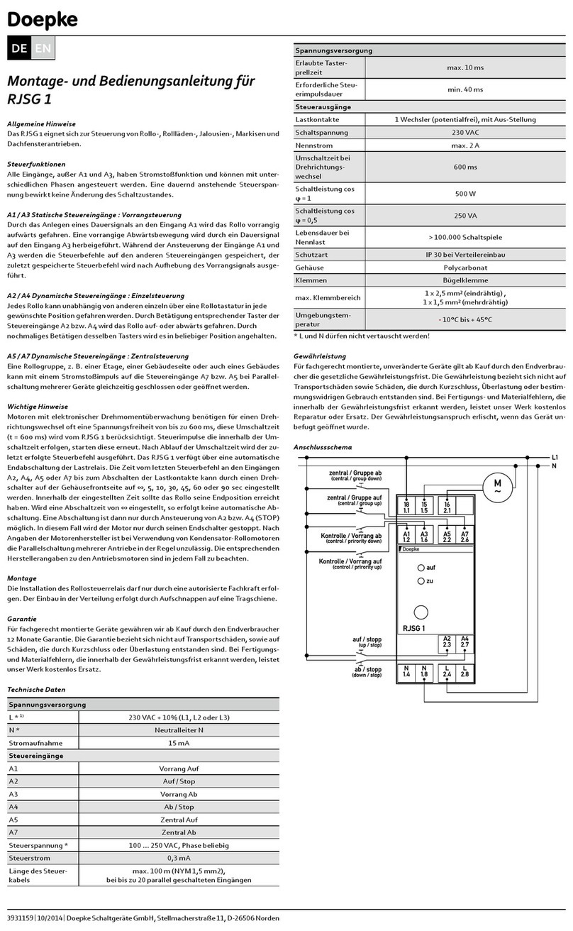
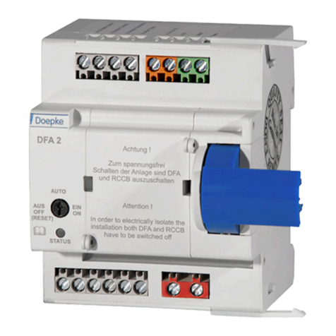
Fernantrieb DFA 2-2
Remote actuator DFA 2-2
Doepke

Montage-
und Bedienungsanleitung
Fernantrieb DFA 2-2
Operating instructions
Remote actuator DFA 2-2
Artikelnummer 3930236 |Stand: 09/2013
Doepke
2

1. Allgemeine Beschreibung ...........................4
2. Vorbereitung................................................4
2.1. Einstellung der automatischen
Wiedereinschaltversuche ...................4
3. Montage und Inbetriebnahme des DFA ......5
3.1. Spannungsversorgung .......................6
3.2. Steuereingänge ..................................6
3.3. Schaltausgänge..................................6
4. Bedienungsanleitung ..................................6
4.1. Drehschaltereinstellung......................6
4.2. Blinkcodes ..........................................8
5. Verdrahtung ................................................8
5.1. Maße ..................................................9
6. Technische Daten .....................................10
7. Garantie ....................................................10
1. General Description ..................................12
2. Preparation ...............................................12
2.1. Preparation for Remote Trip Facility ...12
3. Installation and Commissioning the DFA ..13
3.1. Power Supply ...................................14
3.2. Control Inputs ...................................14
3.3. Switching Outputs.............................14
4. Operating Instructions...............................14
4.1. Rotary Switch Settings .....................14
4.2. Flash Codes .....................................16
5. Wiring........................................................16
5.1. Dimensions.......................................17
6. Technical Data ..........................................18
7. Guarantee .................................................18
Inhalt
3

1. Allgemeine Beschreibung
Der Fernantrieb DFA ist eine nachrüstbare motorbetriebene Fernbetätigung für Fehlerstromschutz-
schalter (RCCB) der Baureihen DFS 2 und DFS 4 mit einem Bemessungsstrom In ≤ 63 A. Es besteht
somit die Möglichkeit, den RCCB aus der Ferne ein- bzw. auszuschalten und auszulösen.
Mit Hilfe eines Drehschalters auf dem Gehäusedeckel kann der DFA außer Betrieb genommen werden,
sodass aus der Ferne keine versehentliche Betätigung, z. B. bei Wartungsarbeiten in der Verteilung,
möglich ist. Wahlweise kann der DFA in einem Automatikmodus betrieben werden, in dem 15 Sekun-
den nach einer Auslösung automatisch ein oder drei Einschaltversuche vorgenommen werden.
!Quetschgefahr!
Der jeweilige Betriebszustand des Fernantriebs wird durch eine grüne LED auf dem Gehäusedeckel
signalisiert.
Die Spannungsversorgung des DFA kann wahlweise mit einer Spannung von 24 VAC oder
24 VDC erfolgen.
2. Vorbereitung
2.1. Einstellung der automatischen Wiedereinschaltversuche
Ab Werk ist die Anzahl der automatischen Wiedereinschaltversuche auf 1 eingestellt. Wir empfehlen
dringend, diese Einstellung aus Sicherheitsgründen beizubehalten. Sind in der Anlage jedoch mehrere
Wiedereinschaltversuche erforderlich, so kann die Anzahl auf 3 erhöht werden. Die Versuche erfolgen
dann jeweils in einem Abstand von 15s nach einer Auslösung.
!Vor der Umstellung ist der DFA unbedingt auszuschalten (AUS) und von der Versorgungsspannung
zu trennen.
Diese Einstellung wird im Gerät vorgenommen. Dazu wird ein Schlitzschraubendreher nacheinander
in die beiden Vertiefungen auf der Gehäusefrontseite gesteckt und dann leicht verdreht, während der
Deckel gleichzeitig angehoben wird. Ein kraftvolles Aufhebeln ist nicht nötig und kann das Gehäuse
beschädigen.
Mit Hilfe einer Spitzzange ist die Kurzschlussbrücke („Jumper“) entsprechend der Grak im Gerät
vorsichtig umzustecken.
Doepke
4

Blick in den geöffneten DFA
Der Deckel ist jetzt wieder zu schließen und kann mit Plomben versehen werden, um einen Eingriff in
das Gerät zu verhindern.
3. Montage und Inbetriebnahme des DFA
Die Montage darf nur durch eine autorisierte Fachkraft vorgenommen werden.
Zunächst sind die beiden beiliegenden Rasthaken seitlich so in den DFA einzuclipsen, dass die Rast-
nasen zum RCCB zeigen.
Zur Montage des Fernantriebes DFA wird dieser links neben dem RCCB platziert. Anschließend wer-
den beide Geräte so zusammengeschoben, dass der Knebel des RCCBs vom Mitnehmerhebel des
DFA umfasst wird und beide Geräte durch die beiden Rastnasen verdrehsicher ineinanderrasten.
DFA 2-2
DFA mit geöffnetem Deckel
Legende
Kurzschlussbrücke (Jumper)
Rasthaken
Mitnehmerhebel
Knebel
Rasthaken
DFA 2-2
5

3.1. Spannungsversorgung
Der DFA kann wahlweise mit einer Spannung von 24VAC oder 24 VDC versorgt werden.
►AC (Klemmen 9 + 10)
An diese Klemmen kann eine 24-V-Wechselspannung als Spannungsversorgung angeschlossen wer-
den. Die Spannungsquelle muss eine Ausgangsleistung von mindestens 10 VA aufweisen.
Wird eine Wechselstromversorgung gewählt, so stellt der DFA an DC+ eine Ausgangsgleichspannung
von 24 VDC zur Verfügung, welche über Taster auf die Steuereingänge gegeben werden kann.
!An diese bereitgestellte DC-Spannung dürfen ausschließlich die Taster für die DFA-
Steuereingänge und keine anderen Verbraucher angeschlossen werden.
►DC+ (Klemme 5) / DC- (Klemme 6)
Steht eine Gleichspannungsversorgung zur Verfügung, so ist sie an diese beiden Klemmen entspre-
chend anzuschließen.
3.2. Steuereingänge
Wird der DFA mit einer Gleichspannung versorgt, so werden die Steuereingänge (einschalten, aus-
schalten) über Taster mit dem Pluspotenzial dieser Versorgungsspannung verbunden und über Tast-
impulse angesteuert. Bei einer Wechselspannungsversorgung dient DC+ als Bezugspunkt für die Taster
der Steuereingänge.
►einschalten (Klemme 4)
Ein Tastimpuls an diesem Eingang führt einen Einschaltvorgang des angeanschten RCCBs aus.
Bendet sich dieser bereits im eingeschalteten Zustand, erfolgt keine Schaltausführung.
►ausschalten (Klemme 3)
Wird auf diesen Eingang ein Tastimpuls gegeben, so wird der montierte RCCB ausgeschaltet, sofern
sich dieser nicht bereits im ausgeschalteten Zustand bendet.
Hinweis: Wird ein Dauersignal auf die Signaleingänge gegeben, z. B. durch einen blockierten Taster,
so erfolgt eine einmalige Ausführung der entsprechenden Funktion. Die anderen Funktionen können
weiterhin genutzt werden.
3.3. Schaltausgänge
Der DFA besitzt einen Relaisausgang, der den blockierten Zustand des DFA signalisiert. Über den
Relaiskontakt lassen sich kleinere Lasten direkt oder größere Lasten über Installationsrelais schalten.
4. Bedienungsanleitung
4.1. Drehschaltereinstellung
Mit dem Drehschalter auf dem Gehäusedeckel lassen sich drei Betriebsarten des DFA auswählen:
Doepke
6

►Betriebsart EIN
Der DFA ist eingeschaltet und führt Schaltbefehle aus, die über die Signaleingänge aktiviert werden.
Die Status-LED leuchtet permanent.
►Betriebsart AUTO
Der DFA ist eingeschaltet und führt Schaltbefehle aus, die über die Signaleingänge aktiviert werden.
Die Status-LED leuchtet permanent.
Je nach Einstellung (s. „Einstellung der automatischen Wiedereinschaltversuche“ auf S. 4) wer-
den in dieser Betriebsart bis zu 3 Einschaltversuche jeweils 15 Sekunden nach einer Auslösung des
geschalteten RCCB durchgeführt. Innerhalb dieser 15 Sekunden wird der Blinkcode 2 über die Status-
LED ausgegeben (s. „Blinkcodes“ auf S. 8), um auf einen folgenden Einschaltversuch hinzuweisen.
Einstellung 1 Wiedereinschaltversuch
Bendet sich der RCCB 5 Sekunden nach dem einmaligen Einschaltversuch nicht in der „eingeschaltet“-
Position, d. h. liegt der Fehler im RCCB-Stromkreis noch vor, wird der DFA blockiert. Wenn eine Auslö-
sung allerdings erst 5 Sekunden oder später nach dem automatischen Einschaltvorgang auftritt, so gilt
dies als neuer Fehler, dem nach 15 Sekunden ein erneuter Einschaltversuch folgt.
Einstellung 3 Wiedereinschaltversuche
Bendet sich der RCCB 5 Sekunden nach dem ersten Einschaltversuch nicht in der „eingeschaltet“-
Position, wird nach weiteren 15 Sekunden ein zweiter Einschaltversuch vorgenommen, dem ggf. nach
15 Sekunden ein dritter Einschaltversuch folgt. Liegt der Fehler im RCCB-Stromkreis weiterhin vor, so
wird der DFA blockiert.
Ist der DFA blockiert, so führt er keine Schaltbefehle oder automatische Einschaltversuche mehr aus,
was durch den Blinkcode 3 und den geschalteten Relaisausgang signalisiert wird. Um die Blockade
aufzuheben, muss der DFA kurzzeitig ausgeschaltet werden (RESET).
►Betriebsart AUS / RESET
Der DFA ist ausgeschaltet und führt somit keine Schaltbefehle aus. Die Status-LED ist erloschen.
!Diese Betriebsart ist zu wählen, wenn:
»Servicearbeiten an der Anlage vorgenommen werden sollen, um ein automatisches Wie-
dereinschalten oder ein Einschalten aus der Ferne zu verhindern. Zusätzlich kann der mon-
tierte RCCB mit einer abschließbaren Wiedereinschaltsperre versehen werden.
»die Blockade nach einer fehlgeschlagenen automatischen Wiedereinschaltung aufgehoben werden soll
7

4.2. Blinkcodes
Die unterschiedlichen Blinkcodes signalisieren den augenblicklichen Zustand des DFA.
Blinkfolge Blinkcode Bedeutung
LED aus 0 ausgeschaltet (gesperrt)
LED ein 1 eingeschaltet (Normalbetrieb)
LED-Takt:
0,1 s ein / 0,9 s aus 2automatische
Einschaltung(en) aktiv
LED-Takt:
1 s ein / 1 s aus 3automatische Einschaltung(en)
fehlgeschlagen (blockiert)
5. Verdrahtung
Folgendes Schema zeigt die Anschlussbelegung des DFA:
123 4 567 8
9 10 11 12 13 15
14 16
0 V
+ 24 V DC
24 V AC
24 V AC/DC
1A
in / out
in
in
in
einschalten
ausschalten
nicht blockiert
blockiert
Bockpol
Bockpol
24 V AC
Doepke
8

Klemme Beschreibung
1 nicht belegt
2 nicht belegt
3 RCCB ausschalten
4 RCCB einschalten
5 +24 VDC (DC+)
6 0 VDC (DC-)
7 nicht belegt
8 nicht belegt
Klemme Beschreibung
9 24 VAC
10 24 VAC
11 Bockpol
12 Bockpol
13 blockiert (NO)
14 nicht blockiert (NC)
15 nicht belegt
16 nicht belegt
!Bei der Verdrahtung des DFA ist unbedingt auf Spannungsfreiheit aller Leitungen zu achten!
Die Spannungsversorgung des DFA darf nicht über den „betätigten“ RCCB erfolgen.
5.1. Maße
9

6. Technische Daten
minimal typisch maximal
Betriebsspannung
AC
Nennbetriebsspannung 21,6 VAC 24,0 VAC 30 VAC
Stromaufnahme 55 mA 60 mA 65 mA
Stromaufnahme im Schaltmoment 600 mA
DC
Nennbetriebsspannung 21,6 VDC 24,0 VDC 26,4 VDC
Stromaufnahme 26 mA 28 mA 30 mA
Stromaufnahme im Schaltmoment 450 mA
Steuereingänge
DC
Steuerspannung 21,6 VDC 24,0 VDC 26,4 VDC
Steuerstrom 1 mA
Steuerimpulsdauer 60 ms
Tasterprellzeit 10 ms
Relaisausgänge
1 Signalrelais (DFA blockiert)
AC/
DC
Spannung 24 V
Nennstrom 1.000 mA
Anschlüsse
Art Zugbügelklemmen
Klemmbereich 0,4 mm Ø 2,5 mm²
Drehmoment 0,6 Nm
Gehäuse
Art Verteilereinbaugehäuse nach DIN 43880 für die
Montage auf Tragschiene nach DIN EN 60715
Maße 72 x 85 x 58 (B x H x T in mm) / 4 TE
Material Polyamid (PA)
allgemeine technische Daten
Betriebstemperatur* - 25 °C + 60 °C
Luftfeuchtigkeit Max. 85 % (Betauung nicht zulässig)
Schutzart IP20
Normen DIN EN 50557, DIN EN 55014-1
Artikelnummern / Zubehör
Fernantrieb DFA2-2 09 100 113
Versorgungsnetzteil RK 24 09 980 654
* Die zulässige Betriebstemperatur des montierten RCCB ist zu beachten.
Doepke
10

7. Garantie
Für fachgerecht montierte, unveränderte Geräte gewähren wir ab Kauf durch den Endverbraucher die
gesetzliche Gewährleistung. Die Garantie bezieht sich nicht auf Transportschäden sowie Schäden,
die durch Kurzschluss oder Überlastung entstanden sind. Bei Fertigungs- und Materialfehlern, die
innerhalb der Gewährleistungsfrist erkannt werden, leistet unser Werk kostenlosen Ersatz. Bei Öffnen
des Gerätes erlischt der Garantieanspruch.
Bei Fragen zum Produkt wenden Sie sich bitte an
Doepke
Schaltgeräte GmbH & Co. KG
Stellmacherstraße 11
D-26506 Norden
Tel.: +49 (0) 4931 1806-0
Fax: +49 (0) 4931 1806-101
http://www.doepke.de
11

1. General Description
The DFA remote actuator is a retro-ttable motor-driven remote control device for residual current cir-
cuit-breakers (DFS 2/4) in the Doepke product range with a rated current In ≤ 63 A. It is thus possible to
connect or disconnect residual current circuit-breakers as well as to trip RCCBs from a remote location.
The DFA can be de-activated with the aid of the rotary switch on the enclosure cover, so that it can-
not be accidentally activated from a remote location, e. g. during maintenance work at the distribution
board. The DFA may optionally also be operated in automatic mode, whereby 15 seconds after a trip
occurs one or three attempts at reconnection are automatically instigated.
!Danger of crushing!
The relevant operating status of the DFA is indicated by a green LED on the enclosure cover.
The DFA can be operated either with a 24VAC or 24 VDC power supply.
2. Preparation
2.1. Setting for attempts at automatic reconnection
The number of automatic reconnection attempts is preset at the factory to 1. For safety reasons we
urgently recommend that this setting be retained. However, if several attempts at reconnection are
required in an installation, then the number may be increased to max. 3 which will take place each
within a space of 15 consecutive seconds after a trip.
!Before changing over it is essential for the DFA to be switched OFF and disconnected from the
power supply.
This setting is carried out within the device. For this purpose insert a standard screwdriver rst into one
and then into the other of the two recesses provided on the housing front and slightly twist while, at the
same time, gently raising the cover (do not lever it open forcibly!).
With the aid of pointed pliers carefully reposition the jumper in the device as shown on the diagram.
Doepke
12

DE
EN
View into the opened DFA
The cover should now be closed and may be secured with lead seals to prevent unauthorised interfer-
ence with the device.
3. Installation and Commissioning the DFA
Installation may only be carried out by an authorized, trained technician.
Firstly the two enclosed snap-on brackets have to be inserted into the side of the DFA so that the snap-
on lugs point towards the residual current breaker.
For mounting the DFA remote actuator the latter is placed to the left, and next to, the residual current
breaker. The two devices are then pushed together so that the toggle of the residual current breaker is
encompassed by the drive lever of the DFA and both devices are securely snapped together by the two
snap-on lugs.
DFA 2-2
open DFA
legend
jumper
snap-on lug
drive lever
toggle
snap-on lug
DFA 2-2
13

3.1. Power Supply
The DFA can be operated either with a 24VAC or 24 VDC power supply.
►AC (Terminals 9 + 10)
At these terminals a 24VAC voltage may be connected as the power supply. The supply point must
be able to provide an output of at least 10 VA. If the 24 VAC supply is selected, the DFA will make a
24VDC output voltage available at terminal 5 (DC+) which may be connected via push-buttons to the
control inputs.
!No other loads other than the buttons for the DFA control inputs may be connected to this avail-
able 24 VDC supply.
►DC+ (Terminal 5) / DC- (Terminal 6)
If a 24VDC voltage supply is available it should be connected to these two terminals.
3.2. Control Inputs
If the DFA is being supplied by 24VDC, then the control inputs (connecting, disconnecting) are to be
connected via push-buttons to the + potential of this supply voltage and triggered via operating pulses.
In the case of a 24VAC power supply, terminal 5 (DC+) serves as reference point for the push- buttons
of the control inputs.
►Connecting (Terminal 4)
A short operating pulse at this input results in the ange-mounted RCCB being switched on. If it is
already connected, no switching will occur.
►Disconnecting (Terminal 3)
If a short operating pulse is given at this input, the mounted RCCB will be switched off, provided it has
not already been disconnected.
Note: If a continuous signal is present at the signal inputs, e. g. because a button is sticking, then the
relevant function will be executed only once. All other functions may continue to be used.
3.3. Switching Outputs
The DFA is equipped with a relay output which signals the status of the RCCB (if blocked). It is pos-
sible to switch smaller loads via this relay contact or, in the case of bigger loads, with the aid of an
installation relay.
4. Operating Instructions
4.1. Rotary Switch Settings
Three operating modes can be selected with the rotary switch on the enclosure cover:
Doepke
14

DE
EN
►Operating mode ON
The DFA is switched on and carries out the control commands which are activated either via the signal
inputs. The status LED is permanently illuminated.
►Operating mode AUTO
The DFA is switched on and carries out the control commands which are activated either via the signal
inputs. The status LED is permanently illuminated.
Depending on the setting (see “Setting for attempts at automatic reconnection”, p. 12) up to 3
reconnection attempts will be carried out in this mode, each within 15 consecutive seconds after the
RCCB has been tripped. During these 15 second periods the status LED will signal Flash Code 2
(see “Flash Codes”, p. 16) to indicate that a reconnection attempt will follow.
Setting for 1 reconnection attempt
If the RCCB has not been switched “ON” after a single reconnection attempt, i.e. if the fault is still pre-
sent in the RCCB’s circuit, the DFA will be inhibited. However, if a trip does not occur until 5 seconds
after an automatic reconnection process, then this will be considered to be a new fault that will be
followed after 15 seconds by a new reconnection attempt.
Setting for 3 reconnection attempts
If the RCCB has not been switched “ON” within 5 seconds of the rst reconnection attempt, a second
reconnection attempt will take place 15 seconds later, followed – if necessary – by a third attempt
15 seconds later still. If the fault in the RCCB’s circuit is still present, then the DFA will be blocked.
If the DFS is inhibited it will not carry out any further switching commands or automatic reconnection
attempts. This will be signalled by Flash Code 3 and the switched relay output. In order to cancel the
inhibition the DFA must be briey switched off (RESET).
►Operating mode OFF
The DFA is switched off and thus does not carry out any control commands. The status LED is extin-
guished.
!This operating mode should be selected
»when maintenance work is to be carried out at the distribution in order to prevent the sys-
tem being switched on from a remote location. The tted RCCB can additionally be equipped
with a lockable restart locking facility.
»if the block caused by a failed automatic reconnection is to be cancelled.
15

4.2. Flash Codes
The different ash codes signal the present status of the DFA.
Signal sequence Flash code Description
LED off 0 DFA inoperative
LED on 1 DFA operating (standard mode)
LED sequence:
0,1 s on / 0,9 s off 2 automatic connection(s) active
LED sequence:
1 s on / 1 s off 3automatic connection(s)
failed (blocked)
5. Wiring
The following diagram shows the connection assignment of the DFA:
123 4 567 8
9 10 11 12 13 15
14 16
0 V
+ 24 V DC
24 V AC
24 V AC/DC
1A
in / out
in
in
in
connecting
disconnecting
operational
blocked
common pole
common pole
24 V AC
Doepke
16

DE
EN
Terminal Description
1 not connected
2 not connected
3 disconnecting RCCB
4 connecting RCCB
5 +24 VDC (DC+)
6 0 VDC (DC-)
7 not connected
8 not connected
Terminal Description
9 24 VAC
10 24 VAC
11 relay output: common pole
12 relay output: common pole
13 relay output: blocked (NO)
14 relay output: operational (NC)
15 not connected
16 not connected
!While so doing it must be ensured that all leads are dead.
The power supply of the DFA must not be realized via the switched RCCB.
5.1. Dimensions
17

6. Technical Data
minimum typical maximum
Power supply
AC
rated voltage 21,6 VAC 24,0 VAC 30 VAC
current input 55 mA 60 mA 65 mA
current input (at switching moment) 600 mA
DC
rated voltage 21,6 VDC 24,0 VDC 26,4 VDC
current input 24 mA 27 mA 30 mA
current input (at switching moment) 500 mA
Control input
DC
control voltage 21,6 VDC 24,0 VDC 26,4 VDC
control current 1 mA
control pulse duration 60 ms
push-button bounce time 10 ms
Relay output
1 signal relay (DFA blocked)
AC/
DC
voltage 24 V
rated current 1.000 mA
Terminals
type screw terminal with strain-relief clamp
terminal cross-section 0,4 mm Ø 2,5 mm²
tightening torque 0,6 Nm
Housing
type distribution board housing in accordance with DIN 43880 for
mounting on DIN rail in accordance with DIN EN 60715
dimensions 72 x 85 x 58 (W x H x D in mm) / 4 module widths
material polyamide (PA)
Other data
operating temperature* - 25 °C + 60 °C
humidity max. 85 % (exposure to dew not permissible)
type of protection IP 20
installation regulations DIN EN 50557, DIN EN 55014-1
Article numbers / accessories
remote actuator DFA2-2 09 100 113
power supply unit RK 24 09 980 654
* Mind the maximum permissible temperature of the mounted RCCB.
Doepke
18

DE
EN
7. Guarantee
All professionally installed, unaltered devices are covered by warranty during the statutory guarantee
period from the day of purchase by the end user. The guarantee is not applicable to damage incurred
during transport or caused by short-circuit or overloading. In the event of defects in workmanship or
material, which are discovered within the guarantee period, the company will provide a replacement
free of charge. The guarantee will be rendered null and void if the device is opened or tampered with.
In case of queries concerning this product please contact:
Doepke
Schaltgeräte GmbH & Co. KG
Stellmacherstraße 11
D-26506 Norden
Tel.: +49 (0) 4931 1806-0
Fax: +49 (0) 4931 1806-101
http://www.doepke.de
19

Satz- und Druckfehler sowie technische Änderungen vorbehalten /
subject to technical changes and misprints
Doepke Schaltgeräte GmbH & Co. KG | Stellmacherstraße 11 | D-26506 Norden |
Art.-Nr. 3930236 | 09/2013
Table of contents
Languages:
Other Doepke Controllers manuals