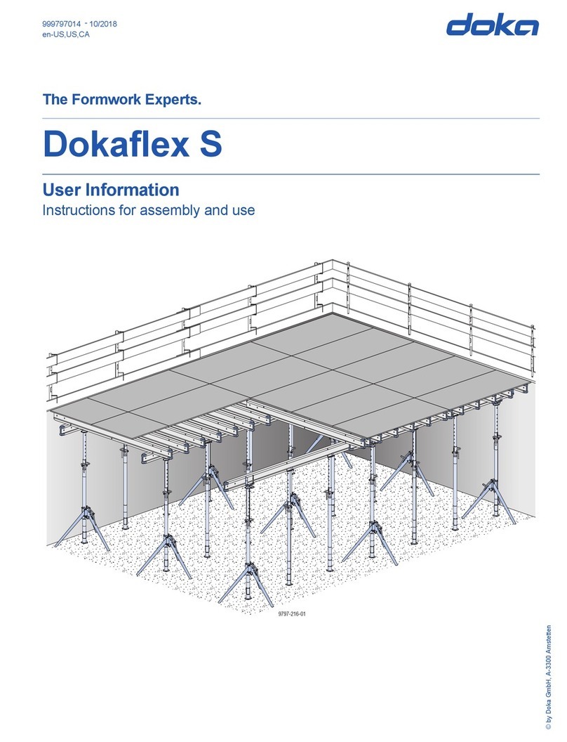
Doka Framed formwork Framax Xlife plus Operation manual

© by Doka GmbH, A-3300 Amstetten
999811202 04/2019
en-GB
-
The Formwork Experts.
Framed formwork Framax Xlife plus
User Information
Instructions for assembly and use (Method statement)
© by Doka GmbH, A-3300 Amstetten
9 -20 -08112 7 1

2999811202 - 04/2019
User Information Framed formwork Framax Xlife plus

User Information Framed formwork Framax Xlife plus
3999811202 - 04/2019
Contents
4Introduction
4Elementary safety warnings
7Doka services
8Framed formwork Framax Xlife plus
9Wall formwork
10 Instructions for assembly and use for room-
high formwork
13 Instructions for assembly and use for high
formwork
16 Framax Xlife plus panel in detail
18 System grid
21 Inter-panel connections
25 Bracing the panels
26 Vertical stacking of panels
40 Tie rod system Framax Xlife plus
52 Length adjustment using closures
53 90 degree corners
65 Acute & obtuse-angled corners
71 Shaft formwork
79 Inter-panel connections for increased tensile
loads
80 Stop-end formwork
83 Wall junctions, offsets and steps
85 Window and door openings
86 Plumbing accessories
89 Pouring platforms
96 Pouring platforms with single brackets
98 Opposing guard-rail
101 Wall formwork at the edge of the structure
103 Ladder system
107 Stripping aid
108 Lifting by crane
110 Transporting, stacking and storing
118 General remarks
118 Areas of use
119 Framax Xlife plus combined with . . .
122 Cleaning and care of your equipment
125 Fall-arrest systems on the structure
126 Formwork planning with Tipos-Doka
128 Component overview

4999811202 - 04/2019
Introduction User Information Framed formwork Framax Xlife plus
Introduction
Elementary safety warnings
User target groups
▪ This booklet is aimed at all persons who will be work-
ing with the Doka product or system that it describes.
It contains information on the standard design for
setting up this system, and on correct, compliant uti-
lisation of the system.
▪ All persons working with the product described
herein must be familiar with the contents of this
booklet and with all the safety instructions it contains.
▪ Persons who are incapable of reading and under-
standing this booklet, or who can do so only with dif-
ficulty, must be instructed and trained by the cus-
tomer.
▪ The customer is to ensure that the information mate-
rials provided by Doka (e.g. User Information book-
lets, Instructions for Assembly and Use, Operating
Instruction manuals, plans etc.) are up to date and
available to all users, and that they have been made
aware of them and have easy access to them at the
usage location.
▪ In the relevant technical documentation and form-
work utilisation plans, Doka shows the workplace
safety precautions that are necessary in order to use
the Doka products safely in the usage situations
shown.
In all cases, users are obliged to ensure compliance
with national laws, standards and regulations
throughout the entire project and to take appropriate
additional or alternative workplace safety precau-
tions where necessary.
Hazard assessment
▪ The customer is responsible for drawing up, docu-
menting, implementing and continually updating a
hazard assessment at every job-site.
This booklet serves as the basis for the site-specific
hazard assessment, and for the instructions given to
users on how to prepare and utilise the system. It
does not substitute for these, however.
Remarks on this booklet
▪ This document can be used as general Instructions
for Assembly and Use (Method Statement) or be
incorporated into site-specific Instructions for
Assembly and Use (Method Statement).
▪ The graphics, animations and videos in this doc-
ument or app sometimes depict partially assem-
bled assemblies and may require additional
safety equipment and/or measures to comply
with safety regulations.
The customer must ensure all applicable regulations
are complied with, even if they are not shown or
implied in the graphics, animations and videos pro-
vided.
▪ Individual sections contain further safety
instructions and/or special warnings as applica-
ble.
Planning
▪ Provide safe workplaces for those using the form-
work (e.g. for when it is being erected/dismantled,
modified or repositioned etc). It must be possible to
get to and from these workplaces via safe access
routes!
▪ If you are considering any deviation from the
details and instructions given in this booklet, or
any application which goes beyond those
described in the booklet, then revised static cal-
culations must be produced for checking, as well
as supplementary assembly instructions.
Regulations; industrial safety
▪ All laws, Standards, industrial safety regulations and
other safety rules applying to the utilisation of our
products in the country and/or region in which you
are operating must be observed at all times.
▪ If a person or object falls against, or into, the side-
guard component and/or any of its accessories, the
component affected may only continue in use after it
has been inspected and passed by an expert.

User Information Framed formwork Framax Xlife plus Introduction
5999811202 - 04/2019
Rules applying during all phases of
the assignment
▪ The customer must ensure that this product is
erected and dismantled, reset and generally used for
its intended purpose in accordance with the applica-
ble laws, standards and rules, under the direction
and supervision of suitably skilled persons.
These persons' mental and physical capacity must
not in any way be impaired by alcohol, medicines or
drugs.
▪ Doka products are technical working appliances
which are intended for industrial / commercial use
only, always in accordance with the respective Doka
User Information booklets or other technical docu-
mentation authored by Doka.
▪ The stability and load-bearing capacity of all compo-
nents and units must be ensured during all phases of
the construction work!
▪ Do not step on or apply strain to cantilevers, clo-
sures, etc. until suitable measures to ensure their
stability have been correctly implemented (e.g. by
tie-backs).
▪ Strict attention to and compliance with the functional
instructions, safety instructions and load specifica-
tions are required. Non-compliance can cause acci-
dents and severe injury (risk of fatality) and consid-
erable damage to property.
▪ Sources of fire in the vicinity of the formwork are pro-
hibited. Heaters are permissible only when used cor-
rectly and situated a correspondingly safe distance
from the formwork.
▪ Customer must give due consideration to any and all
effects of the weather on the equipment and regards
both its use and storage (e.g. slippery surfaces, risk
of slipping, effects of the wind, etc.) and implement
appropriate precautionary measures to secure the
equipment and surrounding areas and to protect
workers.
▪ All connections must be checked at regular intervals
to ensure that they are secure and in full working
order.
In particular threaded connections and wedged con-
nections have to be checked and retightened as nec-
essary in accordance with activity on the jobsite and
especially after out-of-the-ordinary occurrences (e.g.
after a storm).
▪ It is strictly forbidden to weld Doka products – in par-
ticular anchoring/tying components, suspension
components, connector components and castings
etc. – or otherwise subject them to heating.
Welding causes serious change in the microstruc-
ture of the materials from which these components
are made. This leads to a dramatic drop in the failure
load, representing a very great risk to safety.
It is permissible to cut individual tie rods to length
with metal cutting discs (introduction of heat at the
end of the rod only), but it is important to ensure that
flying sparks do not heat and thus damage other tie
rods.
The only articles which are allowed to be welded are
those for which the Doka literature expressly points
out that welding is permitted.
Assembly
▪ The equipment/system must be inspected by the
customer before use, to ensure that it is in an accept-
able condition. Steps must be taken to exclude com-
ponents that are damaged, deformed, or weakened
due to wear, corrosion or rot (e.g. fungal decay).
▪ Using our safety and formwork systems together
with those of other manufacturers can create risks
that may lead to injury and damage to property. This
requires separate verification.
▪ The equipment/system must be assembled and
erected in accordance with the applicable laws,
standards and rules by trained customer personnel
whilst maintaining any applicable safety inspections
that may be required.
▪ It is not permitted to modify Doka products; such
modifications constitute a safety risk.
Closing the formwork
▪ Doka products and systems must be set up so that
all loads acting upon them are safely transferred!
Pouring
▪ Do not exceed the permitted fresh-concrete pres-
sures. Over-high pouring rates overload the form-
work, cause greater deflection and risk breakage.
Stripping the formwork
▪ Do not strip out the formwork until the concrete has
reached sufficient strength and the person in charge
has given the order for the formwork to be stripped
out!
▪ When stripping out the formwork, never use the
crane to break concrete cohesion. Use suitable tools
such as timber wedges, special pry-bars or system
features such as Framax stripping corners.
▪ When stripping out the formwork, do not endanger
the stability of any part of the structure, or of any
scaffolding, platforms or formwork that is still in
place!
6999811202 - 04/2019
Introduction User Information Framed formwork Framax Xlife plus
Transporting, stacking and storing
▪ Observe all country-specific regulations applying to
the handling of formwork and scaffolding. For system
formwork the Doka slinging means stated in this
booklet must be used – this is a mandatory require-
ment.
If the type of sling is not specified in this document,
the customer must use slinging means that are suit-
able for the application envisaged and that comply
with the regulations.
▪ When lifting, always make sure that the unit to be
lifted and its individual parts can absorb the forces
that occur.
▪ Remove loose parts or secure them so that they can-
not slip out of position and drop.
▪ All components must be stored safely, following all
the special Doka instructions given in the relevant
sections of this document!
Maintenance
▪ Only original Doka components may be used as
spare parts. Repairs may only be carried out by the
manufacturer or authorised facilities.
Miscellaneous
The weights as stated are averages for new material;
actual weights can differ, depending on material toler-
ances. Dirt accretions, moisture saturation, etc. can
also affect weight.
We reserve the right to make alterations in the interests
of technical progress.
Symbols used
The following symbols are used in this document:
DANGER
This is a notifier drawing attention to an
extremely dangerous situation in which non-
compliance with this notifier will lead to death
or severe, irreversible injury.
WARNING
This is a notifier drawing attention to a dan-
gerous situation in which non-compliance
with this notifier can lead to death or severe,
irreversible injury.
CAUTION
This is a notifier drawing attention to a dan-
gerous situation in which non-compliance
with this notifier can lead to slight, reversible
injury.
NOTICE
This is a notifier drawing attention to a situa-
tion in which non-compliance with this noti-
fier can lead to malfunctions or damage to
property.
Instruction
Indicates that actions have to be performed
by the user.
Sight-check
Indicates that you need to do a sight-check
to make sure that necessary actions have
been carried out.
Tip
Points out useful practical tips.
Reference
Cross-references other documents.

User Information Framed formwork Framax Xlife plus Introduction
7999811202 - 04/2019
Doka services
Support in every stage of the project
▪ Project success assured by products and services
from a single source.
▪ Competent support from planning through to assem-
bly directly on site. High performance, in all stages of the project
Project assistance from start to finish
Every single project is unique and calls for individual-
ised solutions. When it comes to the forming opera-
tions, the Doka team can help you with its consulting,
planning and ancillary services in the field, enabling
you to carry out your project effectively, safely and reli-
ably. Doka assists you with individual consulting ser-
vices and customised training courses.
Efficient planning for a safe project sequence
Efficient formwork solutions can be developed eco-
nomically only if there is an understanding of project
requirements and construction processes. This under-
standing is the basis of Doka engineering services.
Optimise construction workflows with Doka
Doka offers special tools that help you in designing
transparent processes. This is the way to speed up
pouring processes, optimise inventories and create
more efficient formwork planning processes.
Custom formwork and on-site assembly
To complement its system formwork range, Doka
offers customised formwork units. And specially
trained personnel assemble load-bearing towers and
formwork on site.
Just-in-time availability
Formwork availability is a crucial factor in realising
your project on time and on budget. The worldwide
logistics network puts the necessary formwork quanti-
ties on site at the agreed time.
Rental and reconditioning service
The formwork material needed for any particular pro-
ject can be rented from Doka’s high-performing rental
park. Doka Reconditioning cleans and overhauls both
client-owned equipment and Doka rental equipment.
Tender Operations
scheduling
Construction
work
Project close-
out
Engineering
▪ Execution planning
▪ Cycle planning
▪ Structure modelling/3D-planning
▪ Assembly drawings
▪ Statical calculation
▪ Concremote
Consulting and training
▪ Project processing on-site
▪ Formwork instructor
▪ Training & consulting
Process optimisation
▪ Concremote
▪ myDoka
▪ Planning software
▪ Depot management
Pre-assembly and assembly
▪ Pre-assembly service
▪ Formwork pre-assembly on
site
Logistics
▪ Organisation of transport & freight
Rental and reconditioning service
▪ Rental service
▪ Formwork returns
▪ Reconditioning & service fixed rates

8999811202 - 04/2019
Introduction User Information Framed formwork Framax Xlife plus
Framed formwork Framax Xlife plus
Panels with centrally arranged form-tie points,
designed to complement Framax Xlife
An extension of the proven Framed formwork system
Framax Xlife, the new Framax Xlife plus panels offer a
fast and reliable way of implementing special require-
ments with respect to form-tie and joint patterns, with
no need to invest in a whole new formwork system.
Faster working
with a single sided, conical tie rod system
▪ the Tie rod system Framax Xlife plus can be oper-
ated from one side, offering savings of up to one third
in forming and stripping times
▪ shorter forming times as some of the tasks have
been eliminated, e.g. cutting and fitting of jacket
tubes and cones
▪ less time spent searching as the form-tie 'parking'
position is right at the form-tie point
Highly cost-efficient
thanks to both tried-and-tested and new product
features
▪ no material costs associated with form-tie points,
e.g. for wearing parts of the form-tie sleeve, jacket
tubes and cones
▪ wide spacing between form-ties (1.35 m apart)
saves up to twelve per cent of the costs for form-tie
points and finishing work on form-tie holes
▪ high numbers of repeat uses made possible by
excellent manufacturing quality and extra-durable
Xlife sheets
▪ steel frames are hot-dip galvanised, both inside and
out, for long lifespan
▪ form ties are opened and closed using a ratchet for
minimal wear-and-tear on equipment
Easy handling and planning
thanks to the consistent system logic
▪ the small number of additional panel types ensures
optimum material use and effective logistics
▪ the extra-large square panel enables vertical stack-
ing with standard horizontal panels, without a multi-
tude of additional small panels
▪ errors in form-tie setting are eliminated since every
single form-tie point is used
Harmonic architectural surfaces
with regular form-tie and joint patterns
▪ consistent joint pattern thanks to matching panel for-
mats, even when combining upright and horizontal
panels
▪ no screw imprints on the concrete because the form-
work sheet is fixed from the rear
▪ centrally arranged form-tie points resulting in sym-
metrical form-tie patterns
▪ aesthetically pleasing form-tie points thanks to uni-
form conical imprints
9 -2 -028112 17

User Information Framed formwork Framax Xlife plus Wall formwork
9999811202 - 04/2019
Wall formwork
AFramax Xlife plus panel (Page 16)
BInter-panel connections (Page 21)
CVertical stacking of panels (Page 26)
DTie rod system (Page 40)
ELength adjustment (Page 52)
F90 degree corners (Page 53)
GAcute & obtuse-angled corners (Page 65)
HStop-end formwork (Page 80)
IPlumbing accessories (Page 86)
JPouring platforms (Page 89)
KOpposing guard-rail (Page 98)
LLadder system (Page 103)
MLifting by crane (Page 108)
9 - -018112 341
B
D
E
F
G
H
I
A
J
M
C
L
K
Permitted fresh-concrete pressure: 80 kN/m2

10 999811202 - 04/2019
Wall formwork User Information Framed formwork Framax Xlife plus
Instructions for assembly and use for room-high formwork
The sequence shown here is based on a straight wall.
However, you should always start to form from the cor-
ner outwards.
Ladders must be located so as to create viable 'traffic
routes' in the horizontal. (On a straight wall, for exam-
ple, one ladder on the first element and another on the
last).
Transporting / handling the panels
➤For offloading panels from a truck, or lifting them on-
site a stack at a time, use the Framax transport gear
(see 'Transporting, stacking and storing').
➤To separate the panels, use Framax transport bolts
and the Doka 4-part chain 3.20m (see 'Transporting,
stacking and storing').
Pre-assembly
➤Pre-assemble elements face-down on an assembly
bench (see 'Inter-panel connections').
➤With the gang-form still flat, mount panel struts to it
(see 'Plumbing accessories').
➤Mount the Ladder system XS (see 'Ladder system').
Closing the formwork
➤Attach the lifting chain to the Framax lifting hook (see
the section headed 'Lifting by crane' and the Operat-
ing Instructions for the 'Framax lifting hook').
➤Raise the gang-form by crane.
➤Spray the formwork sheet with release agent (see
the section headed 'Cleaning and care of your equip-
ment').
➤Fly the gang-form to its new location.
➤Fix the panel struts firmly to the ground (see the sec-
tion headed 'Plumbing accessories').
The gang-form is now stable and can be plumbed
and aligned exactly, with no need for the crane.
➤Detach the gang-form from the crane. The crew can
reach the slinging points by standing on a step stool.
➤Slot the pouring platform into place (see the section
headed 'Pouring platforms').
Max. load:
▪ Spread angle β up to 30°:
1000 kg (2200 lbs) / Framax lifting hook
▪ Spread angle β up to 7.5°:
1500 kg (3300 lbs) / Framax lifting hook
Framax lifting hooks with the rated load-bearing
capacity of max. 1000 kg (2200 lbs) also comply with
the requirements for a load bearing capacity of
1500 kg (3300 lbs) at a spread angle β ≤ 7.5°.
98112-227-01
98112-227-02
CAUTION
Never use a sledge-hammer to plumb and align
the panels!
This would damage the profiles of the gangs.
➤Use only proper plumbing tools (e.g. a spe-
cial pry-bar) that cannot cause any damage.
98112-227-03
98112-227-04

User Information Framed formwork Framax Xlife plus Wall formwork
11999811202 - 04/2019
➤Detach the pouring platform from the crane.
➤Continue lining up further gang-forms in this way,
and link them together (see the section headed
'Inter-panel connections').
➤Fit end-of-platform sideguards (see the section
headed 'Pouring platforms').
Erecting the opposing formwork:
Once the reinforcement has been placed, the form-
work can be closed.
➤Mount the opposing guard-rail to the (laid-flat) gang-
form of the opposing formwork (see 'Opposing
guard-rails').
➤Spray the formwork sheet with release agent (see
'Cleaning and care').
➤Lift the opposing formwork by crane to its next loca-
tion.
➤Fit the form ties (see 'Tie-rod system').
➤Detach the gang-form from the crane (wherever pos-
sible, operate the lifting hook from the opposite pour-
ing platform).
➤Continue lining up further gang-forms in this way,
and link them together (see 'Inter-panel connec-
tions').
Pouring
Observe the following guidelines:
▪ The section headed 'Pressure of fresh concrete on
vertical formwork – DIN 18218' in the Calculation
Guide 'Doka formwork engineering'
▪ DIN 4235 Part 2 - 'Compacting of concrete by vibrat-
ing'
➤Pour the concrete.
WARNING
There is not yet an opposing guard-rail on the
formwork!
Danger to life from fatal falls!
➤Either use personal protective equipment to
protect against falls (e.g. Doka personal fall-
arrest set)
or
mount an opposing guard-rail to the gang-
form while this is still being pre-assembled in
a flat position.
98112-228-01
Before disconnecting from the crane:
➤If there are no panel struts on the opposing
formwork, do not disconnect the element
from the crane until a large enough number
of form ties have been installed to keep it
safely in the upright.
Permitted fresh-concrete pressure: 80 kN/m2
NOTICE
➤Do not exceed the maximum permissible
rate of placing.
98112-228-02

12 999811202 - 04/2019
Wall formwork User Information Framed formwork Framax Xlife plus
➤Make only moderate use of vibrators, carefully co-
ordinating the times and locations of vibrator use.
Stripping the formwork
➤Remove any loose items from the formwork and plat-
forms, or secure them firmly.
➤Attach the gang-form of the opposing formwork to
the crane (wherever possible, operate the lifting
hook from the opposite pouring platform).
➤Take out the form ties and undo the connectors to
the adjacent panels.
➤Lift the gang-form away and to its next location.
If the gang-form is 'parked' prior to its next use, it
must have sufficient stability (see the section headed
'Plumbing accessories').
Gang-forms with only one panel strut must not be
'parked' upright, but placed face-down.
➤Clean residual concrete off the formwork sheet (see
the section headed ‘Cleaning and care’).
➤Where the gang-form has panel struts and a pouring
platform attached to it, first attach this gang-form to
the crane, and only then detach the floor anchorages
of the panel struts.
NOTICE
➤Comply with the stipulated stripping times.
98112-226-01
98112-226-02
In order to speed up operations when lifting
and repositioning by crane, most of the form
ties can be taken out in advance.
Important!
There must be at least as many form ties left in
place as are needed to keep the panel safely
in the upright.
WARNING
The formwork tends to adhere to the concrete.
When stripping the formwork, do not try to
break concrete cohesion using the crane!
Risk of crane overload.
➤Use suitable tools such as timber wedges or
a special pry-bar to detach the formwork
from the concrete.
98112-227-05

User Information Framed formwork Framax Xlife plus Wall formwork
13999811202 - 04/2019
Instructions for assembly and use for high formwork
The sequence shown here is based on a straight wall.
However, you should always start to form from the cor-
ner outwards.
Ladders must be located so as to create viable 'traffic
routes' in the horizontal. (On a straight wall, for exam-
ple, one ladder on the first element and another on the
last).
Transporting / handling the panels
➤For offloading panels from a truck, or lifting them on-
site a stack at a time, use the Framax transport gear
(see 'Transporting, stacking and storing').
➤To separate the panels, use Framax transport bolts
and the Doka 4-part chain 3.20m (see 'Transporting,
stacking and storing').
Pre-assembly
➤Pre-assemble elements face-down on an assembly
bench (see 'Inter-panel connections').
➤Only mount the platforms, ladder system and panel
struts to the gang-form when this is in the flat position
(see 'Pouring platforms', 'Ladder system' and
'Plumbing accessories').
Closing the formwork
➤Attach the lifting chain to the Framax lifting hook (see
the section headed 'Lifting by crane' and the Operat-
ing Instructions for the 'Framax lifting hook').
➤Raise the gang-form by crane.
➤Spray the formwork sheet with release agent (see
the section headed 'Cleaning and care of your equip-
ment').
➤Fly the gang-form to its new location.
➤Fix the panel struts firmly to the ground (see the sec-
tion headed 'Plumbing accessories').
The gang-form is now stable and can be plumbed
and aligned exactly, with no need for the crane.
➤Detach the gang-form from the crane.
➤Continue lining up further gang-forms in this way,
and link them together (see the section headed
'Inter-panel connections').
APlatform
BLadder system
CPanel strut
Max. load:
▪ Spread angle β up to 30°:
1000 kg (2200 lbs) / Framax lifting hook
▪ Spread angle β up to 7.5°:
1500 kg (3300 lbs) / Framax lifting hook
Framax lifting hooks with the rated load-bearing
capacity of max. 1000 kg (2200 lbs) also comply with
the requirements for a load bearing capacity of
1500 kg (3300 lbs) at a spread angle β ≤ 7.5°.
98112-230-01
A
B
C
CAUTION
Never use a sledge-hammer to plumb and align
the panels!
This would damage the profiles of the gangs.
➤Use only proper plumbing tools (e.g. a spe-
cial pry-bar) that cannot cause any damage.
WARNING
There is not yet an opposing guard-rail on the
formwork!
Danger to life from fatal falls!
➤Either use personal protective equipment to
protect against falls (e.g. Doka personal fall-
arrest set)
or
mount an opposing guard-rail to the gang-
form while this is still being pre-assembled in
a flat position.
98112-230-02

14 999811202 - 04/2019
Wall formwork User Information Framed formwork Framax Xlife plus
Erecting the opposing formwork:
Once the reinforcement has been placed, the form-
work can be closed.
➤Spray the formwork sheet with release agent (see
'Cleaning and care').
➤Lift the opposing formwork by crane to its next loca-
tion.
➤Working from the ground, insert the bottom two rows
of form ties (see 'Form-tie system').
➤Detach the gang-form from the crane.
➤Insert the remaining form ties. These form-tie loca-
tions can be reached from the platforms.
➤Continue lining up further gang-forms in this way,
and link them together (see 'Inter-panel connec-
tions').
Pouring
Observe the following guidelines:
▪ The section headed 'Pressure of fresh concrete on
vertical formwork – DIN 18218' in the Calculation
Guide 'Doka formwork engineering'
▪ DIN 4235 Part 2 - 'Compacting of concrete by vibrat-
ing'
➤Pour the concrete.
➤Make only moderate use of vibrators, carefully co-
ordinating the times and locations of vibrator use.
WARNING
There is not yet an opposing guard-rail on the
formwork!
Danger to life from fatal falls!
➤Use personal fall arrest systems to protect
against falls (e.g. Doka safety harness).
Before disconnecting from the crane:
➤If there are no panel struts on the opposing
formwork, do not disconnect the element
from the crane until a large enough number
of form ties have been installed to keep it
safely in the upright.
98112-229-03
Permitted fresh-concrete pressure: 80 kN/m2
NOTICE
➤Do not exceed the maximum permissible
rate of placing.
98112-229-01

User Information Framed formwork Framax Xlife plus Wall formwork
15999811202 - 04/2019
Stripping the formwork
➤Remove any loose items from the formwork and plat-
forms, or secure them firmly.
Begin work on striking the formwork on the oppos-
ing formwork:
➤Undo the connectors to the adjacent panels.
➤Take out the form ties from the two top rows of ties.
These form-tie locations can be reached from the
platforms.
➤Attach the gang-form (incl. platforms) to the crane.
➤Working from the ground, take out the bottom two
rows of form ties.
➤Lift the gang-form away and to its next location, or
place it flat on its back for intermediate storage.
➤Clean residual concrete off the formwork sheet (see
the section headed ‘Cleaning and care’).
➤Where the gang-form has panel struts attached to it,
first attach this gang-form to the crane, and only then
detach the floor anchorages of the panel struts.
NOTICE
➤Comply with the stipulated stripping times.
WARNING
➤There must be at least as many form ties left
in place as are needed to keep the panel
safely in the upright.
WARNING
The formwork tends to adhere to the concrete.
When stripping the formwork, do not try to
break concrete cohesion using the crane!
Risk of crane overload.
➤Use suitable tools such as timber wedges or
a special pry-bar to detach the formwork
from the concrete.
98112-229-02
WARNING
There is not yet an opposing guard-rail on the
formwork!
Danger to life from fatal falls!
➤Use personal protective equipment to pro-
tect against falls (e.g. Doka personal fall-
arrest set).
98112-230-03

16 999811202 - 04/2019
Wall formwork User Information Framed formwork Framax Xlife plus
Framax Xlife plus panel in detail
High load-bearing capacity Clean concrete surfaces with the
innovative Xlife sheet
The Xlife sheet consists of a combination of a tradi-
tional plywood core and a novel and innovative
plastic coating.
This combination of materials ensures high numbers of
repeat uses, with superb concrete results every time,
and reduces the proneness to damage.
▪ High quality concrete finish
▪ Less touching-up needed
▪ Less cleaning work - the Xlife sheet can also be
cleaned using a high-pressure spray cleaner
▪ Because the Xlife sheet is screwed on from the rear,
this leaves no screw imprints on the concrete
Dimensionally stable, galvanised and
powder-coated steel frame
a ... 123 mm
▪ Dimensionally stable frame profiles
▪ Strong cross-profiles
▪ Powder coated, so easy to clean
▪ Edges are easy to clean - so panels always abut
tightly
▪ All-round hardware slot for fastening the inter-panel
connectors at any point required
▪ Hot-dip galvanised for long life
▪ Edges of formwork sheet are protected by frame pro-
file
▪ Cross boreholes for corner configurations and stop-
ends
80 kN/m2 pressure of fresh concrete acting on whole
area, to DIN 18218, where the surface planeness tol-
erances to DIN 18202 Table 3 Line 6 are observed.
AFrame profile
BCross borehole
CContinuous hardware slot for inter-panel connectors
DXlife sheet
ESilicone sealing strip
WARNING
➤It is forbidden to climb on the cross-profiles.
The cross-profiles are NOT a substitute for a
ladder.
9764-244-01
A
C
D
a
B
E

User Information Framed formwork Framax Xlife plus Wall formwork
17999811202 - 04/2019
Accessories are easy to fasten, in the
integrated waling system
Form-tie sleeves
a ... diam. 32 mm
b ... diam. 80 mm
▪ Large, centrally arranged form-tie sleeves with steel
sealing edge
▪ Only 2 form ties are needed for every 2.70 m of panel
height
Handles
Lifting edge
▪ Practical lifting edge, as an insertion point for the
plumbing tool
AFramax Xlife plus panel
BFramax wedge clamp
CFramax universal waling
9727-280-01
A
B
C
98112-208-03
a
b
AIntegral handle
WARNING
Do not use these handles as slinging points for
crane-handling!
Danger of formwork dropping from crane!
➤Use only suitable load-carrying equipment
and slinging points. See 'Resetting by crane'
and 'Transporting, stacking and storing'.
BLifting edge
98112-208-01
A
98112-208-02
B
B

18 999811202 - 04/2019
Wall formwork User Information Framed formwork Framax Xlife plus
System grid
The heights and widths of the Framax Xlife plus panels
together result in a logical, advantageous incre-
ment-grid that makes this formwork highly flexible and
economical.
▪ Easy planning and forming
▪ 15 cm grid with only 7 different panel widths
▪ Very few closures needed
▪ Clear joint pattern
▪ Symmetrically arranged, centred form ties
9 112- 5-01820

User Information Framed formwork Framax Xlife plus Wall formwork
19999811202 - 04/2019
Panel size-grid (including form-tie
pattern)
Framax Xlife plus panels
Panel widths
2.70m 1.35m
Panel heights
1.35m2.70m3.30m
57.5 57.5155.0 67.5 67.5
67.5
67.5
57.5 57.5
155.0
47.0 47.0
118.0 118.0
Panel widths
0.90m 0.75m 0.60m 0.45m 0.30m
Panel heights
0.60m1.35m2.70m3.30m
45.0 45.0 37.5 37.5 30.0 30.0 22.5 22.5 15.0
/
15.0
30.0
30.0
67.5
67.5
57.5 57.5
155.0
47.0 47.0
118.0 118.0

20 999811202 - 04/2019
Wall formwork User Information Framed formwork Framax Xlife plus
Framax Xlife plus inside corner 30/30cm
0.30 x 0.30m
Panel heights
0.60m1.35m2.70m3.30m
Table of contents
Other Doka Construction Equipment manuals

Doka
Doka 150F Operator's manual

Doka
Doka Ringlock Operation manual

Doka
Doka Staxo 100 Operation manual

Doka
Doka Xsafe plus Operation manual

Doka
Doka T Operation manual

Doka
Doka Framax stripping corner I Series User manual

Doka
Doka Platform SCP Assembly instructions

Doka
Doka Dokaflex 30 tec Series Operation manual

Doka
Doka Ringlock Operator's manual

Doka
Doka Dokaflex S Operator's manual