The Formwork Experts
4999771002 - 08/2008 Ü
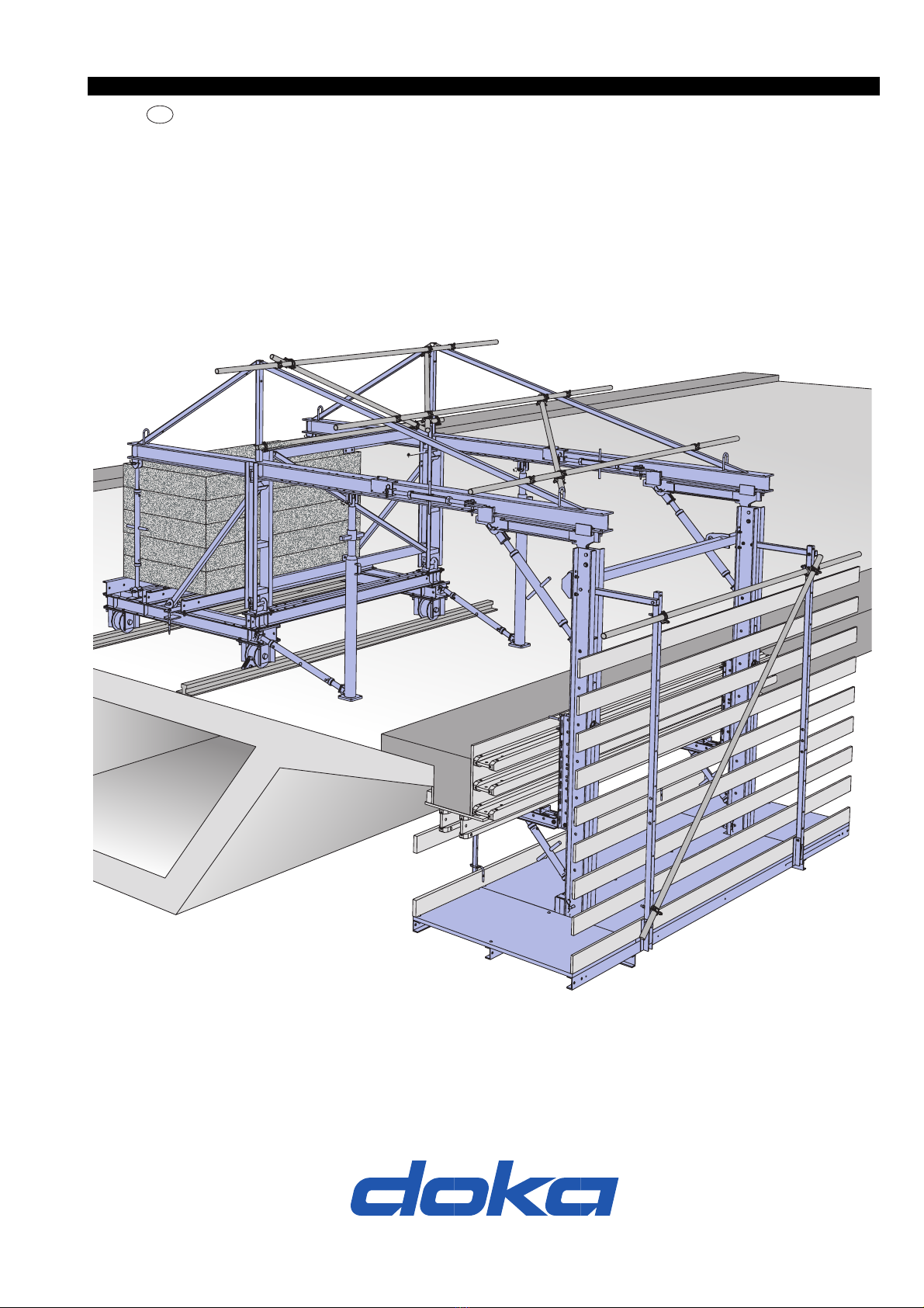
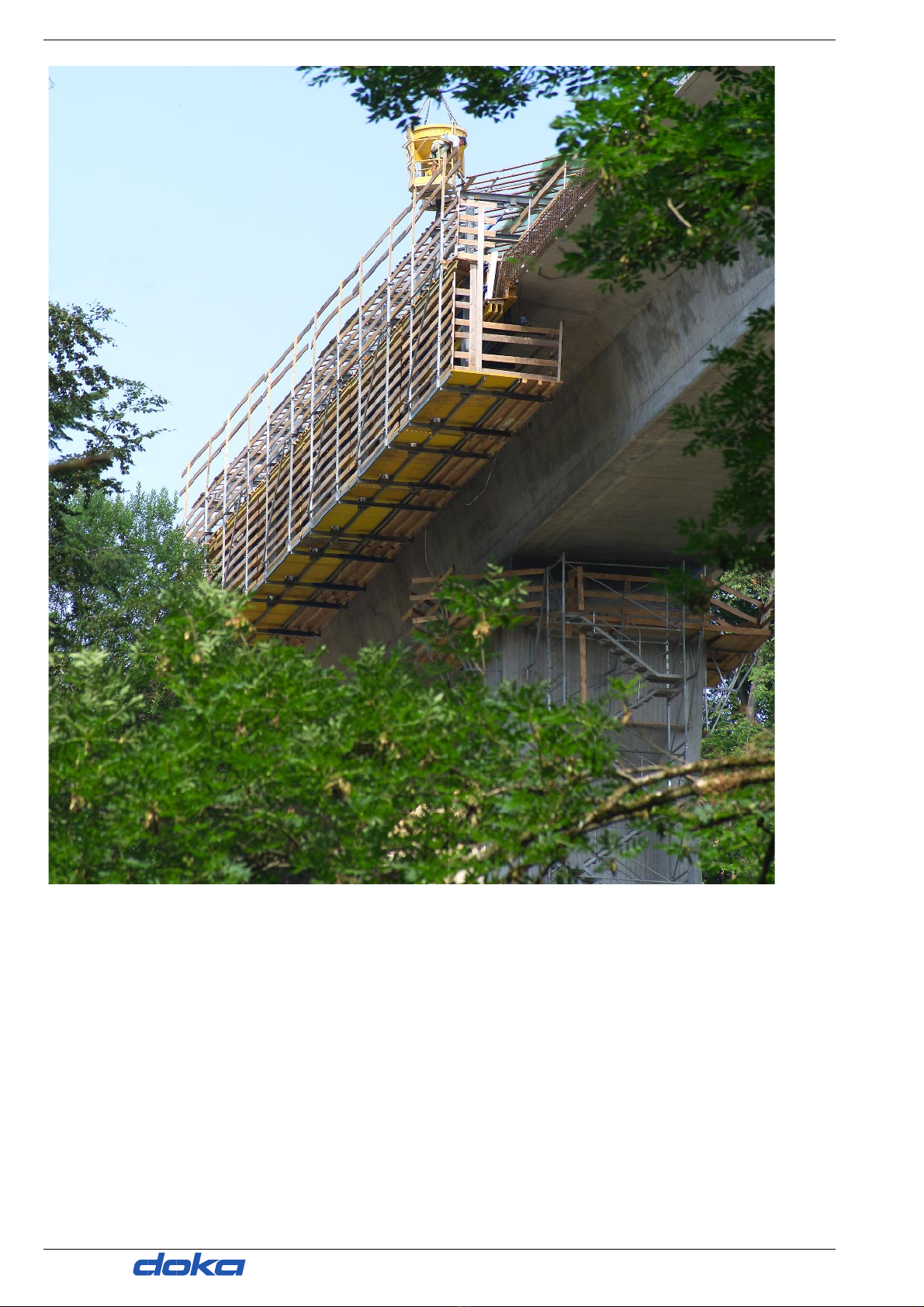
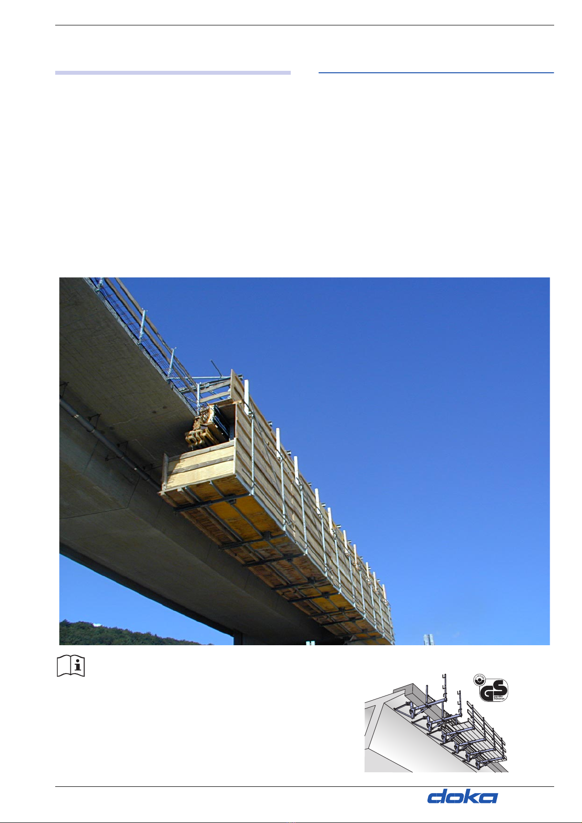
Introduction User information Doka forming wagon T
Elementary safety warnings
User target groups
●This User Information booklet (Method State-
ment) is aimed at everyone who will be working
with the Doka product or system it describes. It
contains information on how to set up this sys-
tem, and on correct, compliant utilisation of the
system.
●All persons working with the product described
herein must be familiar with the contents of this
manual and with all the safety instructions it con-
tains.
●Persons who are incapable of reading and under-
standing this booklet, or who can do so only with
difficulty, must be instructed and trained by the
customer.
●The customer is to ensure that the information
materials provided by Doka (e.g. User Informa-
tion booklets, Instructions for Assembly and Use,
Operating Instruction manuals, plans etc.) are
available to all users, and that they have been
made aware of them and have easy access to
them at the usage location.
Remarks on this document
●This User Information booklet can also be used
as a generic method statement or incorporated
with a site-specific method statement.
●Many of the illustrations in this booklet show the
situation during formwork assembly and are
therefore not always complete from the safety
point of view.
●Further safety instructions, especially warnings,
will be found in the individual sections of this
document!
Planning
●Provide safe workplaces for those using the
formwork (e.g. for when it is being erected/dis-
mantled, modified or repositioned etc). It must be
possible to get to and from these workplaces via
safe access routes!
●If you are considering any deviation from the
details and instructions given in this booklet, or
any application which goes beyond those
described in the booklet, then revised static cal-
culations must be produced for checking, as well
as supplementary assembly instructions.
Rules applying during all phases of
the assignment:
●The customer must ensure that this product is
erected and dismantled, reset and generally used
for its intended purpose under the direction and
supervision of suitably skilled persons with the
authority to issue instructions.
●Doka products are ONLY to be used in accord-
ance with the Doka User Information booklets or
other technical documentation provided by
Doka.
●The stability of all components and units must be
ensured during all phases of the construction
work!
●The functional/technical instructions, safety
warnings and loading data must all be strictly
observed and complied with. Failure to do so can
cause accidents and severe (even life-threaten-
ing) damage to health, as well as very great
material damage.
●Fire-sources are not permitted anywhere near
the formwork. Heating appliances are only
allowed if properly and expertly used, and set up
a safe distance away from the formwork.
●The work must take account of the weather con-
ditions (e.g. risk of slippage). In extreme weather,
steps must be taken in good time to safeguard
the equipment, and the immediate vicinity of the
equipment, and to protect employees.
●All connections must be checked regularly to
ensure that they still fit properly and are function-
ing correctly.
It is very important to check all screw-type con-
nections and wedge-clamped joins whenever the
construction operations require (particularly
after exceptional events such as storms), and to
tighten them if necessary.
Assembly
●The equipment/system must be inspected by the
customer before use, to ensure that it is in suita-
ble condition. Steps must be taken to rule out the
use of any components that are damaged,
deformed, or weakened due to wear, corrosion or
rot.
●Combining our formwork systems with those of
other manufacturers could be dangerous, risking
damage to both health and property. If you
intend to combine different systems, please con-
tact Doka for advice first.
●The assembly work must be carried out by suita-
bly qualified employees of the client's.