manuals.online logo
Brands
  1. Home
  2. •
  3. Brands
  4. •
  5. dol sensors
  6. •
  7. Accessories
  8. •
  9. dol sensors 45R-T Manual

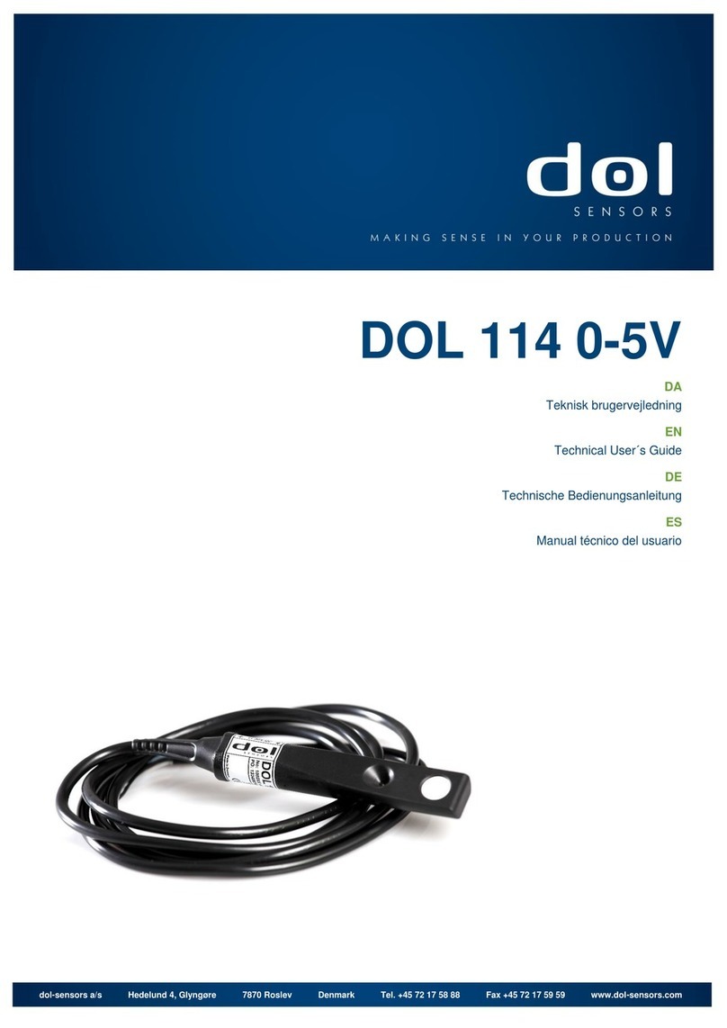
dol sensors 45R-T Manual

Technical User Guide
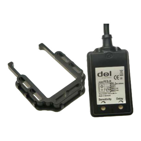
DOL 45R-T
Capacitive Relay-Sensor
For other language variants of this document we refer to www.dol-sensors.com or
your local dealer.
dol-sensors a/s – Agro Food Park 15 – DK-8200 Aarhus N – T: +45 7217 5888 – F: +45 7217 5959 – www.dol-sensors.com
Technical User Guide
2www.dol-sensors.com DOL 45R-T
1 Product description
DOL 45R-T is designed for general detection of feed, grain and solids in tanks, silos and containers. The pow-
erful integrated relay means that it can control many functions directly.
The sensor's electronics are completely embedded in a thermoplastic casing. This achieves a very high resis-
tance to moisture and other external influences in aggressive environments. The sensor is CE, C-UL and UL
approved and has a high immunity to noise from electric communication (e.g. from mobile phone) and tran-
sients (e.g. from motors and contactors). This makes the sensor very reliable and dependable in operation.
2 Mounting guide
Figure1: DOL 45R T-sensor montering
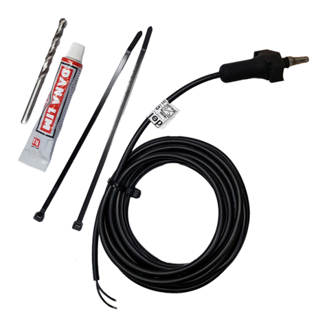
Use the supplied cable ties to mount the sensor on the feed line.
The sensor only works when mounted on plastic tubes The sensor must
be in contact with the plastic tube. This can be verified be checking that
the edge of the sensor is flush with the base of the fitting.
3 Installation guide
Installation, servicing and troubleshooting of all electrical equipment must be carried out by quali-
fied personnel in compliance with the applicable national and international standard EN 60204-1
and any other EU standards that are applicable in Europe.
Supply voltage is connected to the blue and brown wire.
The load is connected in series with the relay contact of the
sensor.
STOP by activating the sensor: Use the black wires 1 and 3.
START by activating the sensor: Use the black wires 1 and 4.
NOTE! The internal relay is in position NC when the supply
voltage is connected and the sensor is activated - wire 1 and 4
are connected.
Technical User Guide
DOL 45R-T www.dol-sensors.com 3
4 User Guide
Activated
Not active
Red
Green
Sensor
No time delay
Delayed
disconnection
Delayed
connection
Red
Red
Green
Green
DOL 41R has no time delay.
DOL 43R has an option for delayed disconnection. Time delay
starts When the activation stops (red flash) When this time stops,
the relay switches back.
DOL 45R has Apart from the settings mentioned above, also has
the option of delayed connection. The time delay starts when the
sensor is affected. When the delay period runs out, the relay will
switch. The relay does not switch back until the activation stops.
Sensitivity Delayed disconnection Delayed connection
41R
43R
45R
DOL
The sensitivity and the delay length are adjusted by two switches. LEDs indicate when the switches are acti-
vated.
Green-0.2 mm +0.2 mm
Sensitivity adjustment (DOL 41R / 43R / 45R)
press 1 x A+B simultaneously
press A or B for -0,2mm +0,2mm
DOL 41R settings is completed press A+B
DOL 43R and DOL 45R continue to the next setting by press A+B
Red +1 sec.+1 min
Time delay setting (DOL 43R/45R)
Press A or B for +1 minute +1 seconds
Eksempel 1xA + 5xB = 65 seconds
DOL 43R settings is completed press A+B
DOL 45R continue to the next setting by press A+B
Yellow On Off
On / off delay (DOL 45R)
press A or B for delayed on or off
press A+B simultaneously = settings completed
Status
Red: sensor is affected
Green: sensor is unaffected
Yellow: Error
Flash: Time delay
Special functions
Factory setting: Hold A + B simultaneously for 15 seconds
Show delay Hold A + press 2xB (Red = 1 min. Green = 1 sek.)
Change delay: Hold A + press 4xB (+10 sec.) hold A + 5+B (÷5 sec.)
Hold A + 6+B (+1 hour.)
Switch off delay.: Hold A + press 7xB
switch off LED Hold A + 8xB
Switch on LED Hold A + 9xB
Technical User Guide
dol-sensors a/s – Agro Food Park 15 – DK-8200 Aarhus N – T: +45 7217 5888 – F: +45 7217 5959 – www.dol-sensors.com
5 Technical data
Electrical
Supply voltage
variant depending
V AC/DC
V AC
10-30
90-250
Frequency Hz 50 - 60
Relay switch max. current V AC 250
Relay switch max. current
AC
A 5 A at cos φ = 1
2 A at cos φ = 0,8
0,35 A at cos φ = 0,4
Relay switch max. current
DC
A 5 A at 0-30 V DC
Safety Relay switches and supply voltage are galvanically separated. Test
voltage 4 kV AC
Specifications
Variant understanding
DOL 45R G T
Thread
Series Tube mount
Distance of activation Adjustable 0-15 mm depending on material Factory setting is grain.
Time delay Adjustable 0 - 240 min. Factory setting is 30 sec.
Mechanical
Sensor length mm
(inches)
110 (4 5/16)
Sensor diameter mm
(inches)
30 (1 3/16)
Cable dimensions mm2
(AWG)
5x 0,75 (5 x 18)
Cable length m 1.5
Cable type UL2517
Weight incl. cable g 290
Environment
Operating temperature °C (°F) -20 - +70 (-4 - +158)
Storage temperature °C (°F) -30 - +85 (-22 - +185)
Protection class IP IP67
Approval CE, C-UL & UL
5.1 Dimensions
603724 • 2022-08-12 • en-US • Made in Denmark

Other dol sensors Accessories manuals

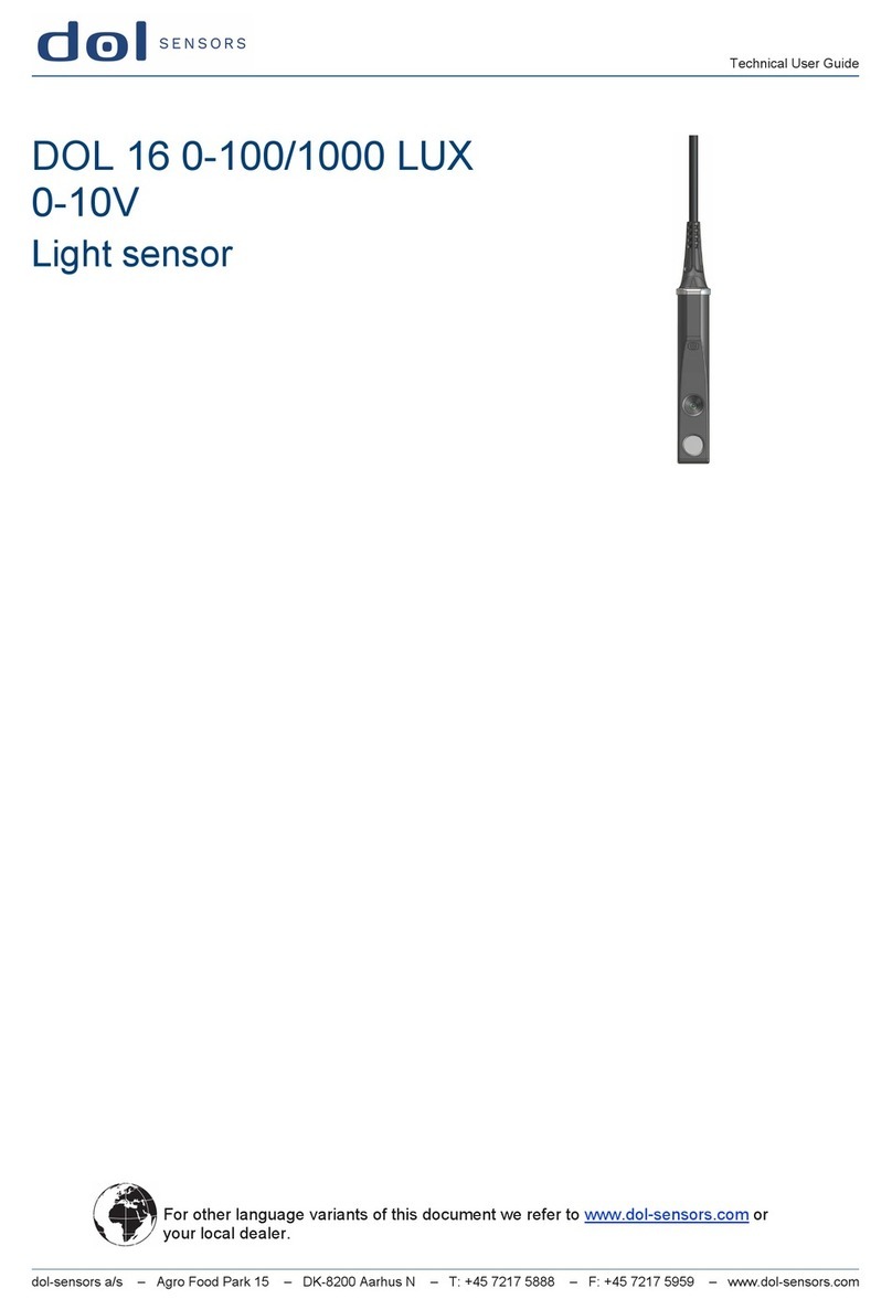
dol sensors DOL 16 0-100/1000 LUX Manual

dol sensors

dol sensors DOL 16 0-100/1000 LUX Manual

dol sensors DOL 51 Manual

dol sensors

dol sensors DOL 51 Manual

dol sensors DOL 25  NPN DOL Manual

dol sensors

dol sensors DOL 25 NPN DOL Manual

dol sensors DOL 140 Manual

dol sensors

dol sensors DOL 140 Manual

dol sensors 114 Manual

dol sensors

dol sensors 114 Manual

dol sensors 16 Manual

dol sensors

dol sensors 16 Manual

dol sensors 20R Manual

dol sensors

dol sensors 20R Manual

dol sensors DOL 104 Manual

dol sensors

dol sensors DOL 104 Manual

dol sensors DOL 16 Manual

dol sensors

dol sensors DOL 16 Manual

dol sensors DOL 53 Manual

dol sensors

dol sensors DOL 53 Manual

dol sensors DOl 10 Manual

dol sensors

dol sensors DOl 10 Manual

dol sensors iDOL 20SCR Manual

dol sensors

dol sensors iDOL 20SCR Manual

dol sensors DOL 20R Manual

dol sensors

dol sensors DOL 20R Manual

dol sensors DOL 26 SCR Manual

dol sensors

dol sensors DOL 26 SCR Manual

dol sensors DOL 16 Manual

dol sensors

dol sensors DOL 16 Manual

dol sensors 114 Manual

dol sensors

dol sensors 114 Manual

Popular Accessories manuals by other brands

PCB Piezotronics IMI SENSORS 670A01 Installation and operating manual

PCB Piezotronics

PCB Piezotronics IMI SENSORS 670A01 Installation and operating manual

Medisana AD 640 operating instructions

Medisana

Medisana AD 640 operating instructions

Philips P-5974 Specifications

Philips

Philips P-5974 Specifications

White Rodgers F145-0825 installation instructions

White Rodgers

White Rodgers F145-0825 installation instructions

Linea 2000 DOMO DO9216AV Instruction booklet

Linea 2000

Linea 2000 DOMO DO9216AV Instruction booklet

Arenti VBELL 1 quick guide

Arenti

Arenti VBELL 1 quick guide

Sonetics SON150 manual

Sonetics

Sonetics SON150 manual

Seifert SlimLine Pro KG 8525 instruction manual

Seifert

Seifert SlimLine Pro KG 8525 instruction manual

ABB CSU-2LV Installation and maintenance guide

ABB

ABB CSU-2LV Installation and maintenance guide

Omron E3F2-Z datasheet

Omron

Omron E3F2-Z datasheet

Liden S29B user manual

Liden

Liden S29B user manual

GARDEN friend T1372011/A Assembly manual

GARDEN friend

GARDEN friend T1372011/A Assembly manual

DVS ZERT Compact Line CL4230.609 Assembly instructions

DVS ZERT

DVS ZERT Compact Line CL4230.609 Assembly instructions

Dacor EF36LNFSS installation instructions

Dacor

Dacor EF36LNFSS installation instructions

Gared Sports Playmaker TOSS BACK Assembly manual

Gared Sports

Gared Sports Playmaker TOSS BACK Assembly manual

Rockwell Automation Allen-Bradley 875L AC user manual

Rockwell Automation

Rockwell Automation Allen-Bradley 875L AC user manual

Vishay VT400 Technical manual

Vishay

Vishay VT400 Technical manual

WAREMA Photo 623 067 Operating and installation guide

WAREMA

WAREMA Photo 623 067 Operating and installation guide

manuals.online logo
manuals.online logoBrands
  • About & Mission
  • Contact us
  • Privacy Policy
  • Terms and Conditions

Copyright 2025 Manuals.Online. All Rights Reserved.