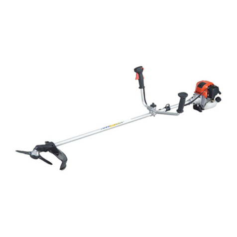
Dolmar BUX360 User manual

GB Cordless Multi Function Instruction manual
Power Head
F
Moteur Multi-Fonctions Sans Fil
Manuel d’instructions
D Multifunktions-Antrieb Betriebsanleitung
I Utensile multifunzione Istruzioni per l’uso
a benzina senza fili
NL Multifunctioneel Gebruiksaanwijzing
accuaandrijfsysteem
E Herramienta Multifuncional Manual de instrucciones
Inalámbrica
P Ferramenta Multifuncional Manual de instruções
a Bateria
DK Batteridrevet multifunktionelt Brugsanvisning
værktøjshoved
GR Ασύρματη μηχανοκίνητη κεφαλή Οδηγίες χρήσης
πολλαπλών χρήσεων
TR
Akülü Çok Fonksiyonlu Güç BaşlığıKullanım kılavuzu
BUX360
BUX361
BUX362
UX360D
UX361D
UX362D
012659

2
1012661
2012942 3010814
4010825 5010815
1
2
3
4
5
6
7
8
9
10 11
1
12
3
13
A
B
14
15
16
1
2

3
6012967 7011715
8012763 9012660
10 012761 11 012762
2
17
18
6
19
5
20
21
22
23
24
1
2
3
4

4
ENGLISH (Original instructions)
Explanation of general view
SPECIFICATIONS
• Due to our continuing programme of research and development, the specifications herein are subject to change without
notice.
• Specifications and battery cartridge may differ from country to country.
• Weight, with battery cartridge, according to EPTA-Procedure 01/2003
Symbol END018-1
The following show the symbols used for the equipment.
Be sure that you understand their meaning before use.
....................... Take particular care and attention.
.......... Read instruction manual.
...................... Do not expose to moisture.
............... Only for EU countries
Do not dispose of electric equipment
or battery pack together with
household waste material!
In observance of European Directive
2002/96/EC on waste electric and
electronic equipment, 2006/66/EC on
batteries and accumulators and
waste batteries and accumulators
and their implementation in
accordance with national laws,
electric equipment and battery pack
that have reached the end of their life
must be collected separately and
returned to an environmentally
compatible recycling facility.
General Power Tool Safety
Warnings GEA010-1
WARNING Read all safety warnings and all
instructions. Failure to follow the warnings and
instructions may result in electric shock, fire and/or
serious injury.
Save all warnings and
instructions for future reference.
IMPORTANT SAFETY
INSTRUCTIONS ENC007-7
FOR BATTERY CARTRIDGE
1. Before using battery cartridge, read all
instructions and cautionary markings on (1)
battery charger, (2) battery, and (3) product using
battery.
2. Do not disassemble battery cartridge.
3. If operating time has become excessively shorter,
stop operating immediately. It may result in a risk
of overheating, possible burns and even an
explosion.
4. If electrolyte gets into your eyes, rinse them out
with clear water and seek medical attention right
away. It may result in loss of your eyesight.
5. Do not short the battery cartridge:
1. Battery cartridge
2. Indicator lamp
3. Switch trigger
4. Hanger (suspension point)
5. Grip
6. Barrier *
7. Shoulder harness
8. Buckle
9. Joint
10. Red indicator
11. Button
12. Lock-off button
13. Reversing switch
14. A position depressed for normal
operation
15. B position depressed for weed
and debris removal
16. Speed change switch lever
17. Indicator lamps
18. CHECK button
19. Clamp
20. Spacer
21. Lock lever
22. Pin
23. Arrow mark
24. Release button
* In some countries, the barrier is not provided with the tool.
Model BUX360, BUX361, BUX362,
UX360D, UX361D, UX362D
No load speed
(with brushcutter attachment EM401MP and nylon cutting head)
High 0 - 6,600 min-1
Low 0 - 4,900 min-1
Overall length 1,019 mm
Net weight 4.6 kg
Rated voltage D.C. 36 V
Standard battery cartridge(s)
Warning: Use only the battery cartridge(s) described. BL3626, BL3622A
Cd
Ni-MH
Li-ion

5
(1) Do not touch the terminals with any
conductive material.
(2) Avoid storing battery cartridge in a container
with other metal objects such as nails, coins,
etc.
(3) Do not expose battery cartridge to water or
rain.
A battery short can cause a large current flow,
overheating, possible burns and even a
breakdown.
6. Do not store the tool and battery cartridge in
locations where the temperature may reach or
exceed 50°C (122°F).
7. Do not incinerate the battery cartridge even if it is
severely damaged or is completely worn out. The
battery cartridge can explode in a fire.
8. Be careful not to drop or strike battery.
9. Do not use a damaged battery.
SAVE THESE INSTRUCTIONS.
Tips for maintaining maximum battery life
1. Charge the battery cartridge before completely
discharged.
Always stop tool operation and charge the battery
cartridge when you notice less tool power.
2. Never recharge a fully charged battery cartridge.
Overcharging shortens the battery service life.
3. Charge the battery cartridge with room
temperature at 10°C - 40°C (50°F - 104°F). Let a hot
battery cartridge cool down before charging it.
4. Charge the battery cartridge once in every six
months if you do not use it for a long period of
time.
INTENDED USE
This cordless multi function power head is intended for
driving an approved attachment listed in the section
“SPECIFICATIONS” of this instruction manual. Never use
the unit for the other purpose.
WARNING:
•Read the instruction manual of the attachment as
well as this instruction manual before using. Failure
to follow the warnings and instructions may result
serious injury.
PARTS DESCRIPTION (Fig. 1)
NOTE:
* In some countries, the barrier is not provided with the
tool.
FUNCTIONAL DESCRIPTION
WARNING:
•Always be sure that the tool is switched off and the
battery cartridge is removed before adjusting or
checking functions on the tool. Failure to switch off
and remove the battery cartridge may result in serious
personal injury from accidental start-up.
Installing or removing battery cartridge
CAUTION:
•Hold the tool and the battery cartridge firmly when
installing or removing battery cartridge. Failure to
hold the tool and the battery cartridge firmly may cause
them to slip off your hands and result in damage to the
tool and battery cartridge and a personal injury.
• Always switch off the tool before installing or removing
of the battery cartridge. (Fig. 2)
To remove the battery cartridge, slide it from the tool while
sliding the button on the front of the cartridge.
To install the battery cartridge, align the tongue on the
battery cartridge with the groove in the housing and slip it
into place. Always insert it all the way until it locks in place
with a little click. If you can see the red indicator on the
upper side of the button, it is not locked completely. Install
it fully until the red indicator cannot be seen. If not, it may
accidentally fall out of the tool, causing injury to you or
someone around you.
NOTE:
• Do not use force when installing the battery cartridge. If
the cartridge does not slide in easily, it is not being
inserted correctly.
Power switch action
WARNING:
•Before inserting the battery cartridge in the tool,
always check to see that the switch trigger
actuates properly and returns to the “OFF”
position when released. Do not pull the switch
trigger hard without pressing in the lock-off button.
This can cause switch breakage. Operating a tool
with a switch that does not actuate properly can lead to
loss of control and serious personal injury. (Fig. 3)
To prevent the switch trigger from being accidentally
pulled, a lock-off button is provided.
To start the tool, press in the lock-off button and pull the
switch trigger. The tool speed is increased by increasing
pressure on the switch trigger. Release the switch trigger
to stop.
Reversing Switch for Debris Removal
(Fig. 4)
This tool has a reversing switch. To remove debris
jammed or entangled in the tool, depress the “B” side of
the switch to reverse the rotation. For normal operation,
depress the “A” side of the switch.
NOTICE:
• Always check the direction of rotation before operation.
• Use the reversing switch only after the tool comes to a
complete stop. Changing the direction of rotation
before the tool stops may damage it.
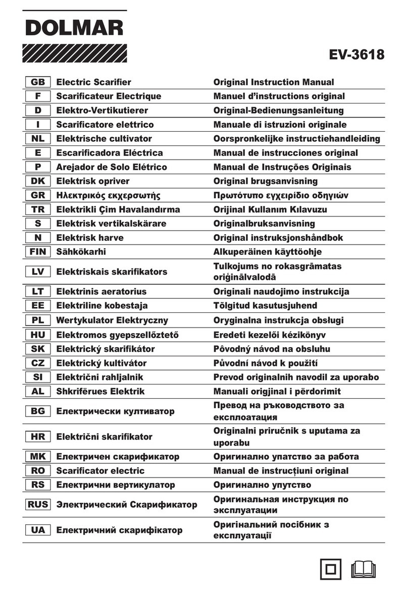
Speed change (Fig. 5)
Two speed ranges can be preselected with the speed
change switch.
Flipping the speed change switch lever to the “1” position
will set the tool to the low speed range and the “2” position
will set the tool to the high speed range.

6
Battery/motor protection system
The battery cartridge and tool are provided with protection
devices that will automatically reduce or cut off power to
the tool when overload situations develop that may cause
damage to the tool or battery cartridge.
If the tool becomes overloaded but not locked up a
protector is provided to reduce the revolutions to protect
the motor. In this case the two indicator lamps described
in the table below do not light or blink.
All other protection functions can be identified by the
indicator lamps described in the table below. (Fig. 6)
010823
Battery remaining capacity indicator (only
for models with Battery BL3622A)
Battery BL3622A is equipped with the battery remaining
capacity indicator. (Fig. 7)
Press the CHECK button to indicate the battery remaining
capacity. The indicator lamps will then light for approx.
three seconds.
011713
• When only the lowermost indicator lamp (next to the
“E”) blinks, or when none of the indicator lamps light,
the battery capacity has run out, so the tool does not
operate. In these cases, charge the battery or replace
the empty battery with a fully charged one.
• When two or more indicator lamps do not light even
after charging is complete, the battery has reached the
end of its service life.
• When the upper two and lower two indicator lamps light
alternately, the battery may have malfunctioned.
Contact your local Makita authorized service center.
NOTE:
• The indicated capacity may be lower than the actual
level during use or immediately after using the tool.
• Depending on the conditions of use and the ambient
temperature, the indication may differ slightly from the
actual capacity.
ASSEMBLY
WARNING:
•Always be sure that the tool is switched off and
battery cartridge is removed before carrying out
any work on the tool. Failure to switch off and remove
the battery cartridge may result in serious personal
injury from accidental start-up.
•Never start the tool unless it is completely
assembled. Operation of the tool in a partially
assembled state may result in serious personal injury
from accidental start-up.
Installing the grip (Fig. 8)
Securely fit the barrier and grip onto the shaft pipe with
two screws and clamps.
Make sure that the spacer on the shaft pipe is located
between the grip and the hanger. Do not remove or shrink
the spacer.
CAUTION:
• Never install the grip on the label or joint.
NOTE:
• In some countries, the barrier and spacer are not
provided with the tool. In that case, align the handle to
Status Action to be taken
– Blinking Battery power has been nearly
used up.
Replace the battery with fully charged one.
– Lighting On
Battery protector is shutting off
the power - battery power has
been used up.
Replace the battery with fully charged one.
Blinking –
Overload protector is shutting off
the power - the motor was locked.
Release the switch trigger and remove the
cause of the motor lock or overload. If the
cutting tool is locked by entangling weeds or the
like, always remove the battery cartridge before
clearing it.
Lighting On – Overheat protector is shutting
off the power - overheating.
Rest the equipment for a while.
Blinking Blinking Electric or electronic malfunction Ask your local authorized service center for
repairs.
Indicator lamps
Remaining capacity
Lighted Off Blinking
E F 70% to 100%
45% to 70%
20% to 45%
0% to 20%
Charge the battery.
The battery may
have malfunctioned.

7
further side of the line which is indicated by the arrow
marks.
Mounting the attachment (Fig. 9)
To mount the attachment to a power unit:
1. Make sure that the lock lever is not tightened.
2. Align the pin with the arrow mark.
3. Insert the shaft into the drive shaft of the power unit
until the release button pops up.
4. Tighten the lock lever firmly as shown.
To remove the attachment, loosen the lock lever, press
the lock button and withdraw the shaft.
NOTICE:
• Do not tighten the lock lever without the shaft of the
attachment inserted. Otherwise the lock lever may
tighten the entrance of the drive shaft too much and
damage it.
Attaching shoulder harness (Fig. 10)
Put the shoulder harness on your left shoulder by putting
your head and right arm through it. Keep the tool on your
right side.
After putting the shoulder harness, attach it to the tool by
connecting the buckles provided on both the tool hook
and the harness. Be sure that the buckles click and lock
completely in place.
Adjust the strap to the suitable length for your operation.
(Fig. 11)
The buckle is provided with a means of quick release
which can be accomplished by simply squeezing the
sides and the buckle.
WARNING:
•Be extremely careful to maintain control of the tool
at all times. Do not allow the tool to be deflected
toward you or anyone in the work vicinity. Failure to
keep control of the tool could result in serious injury to
the bystander and the operator.
MAINTENANCE
WARNING:
•Always be sure that the tool is switched off and
battery cartridge is removed before attempting to
perform inspection or maintenance on the tool.
Failure to switch off and remove the battery cartridge
may result in serious personal injury from accidental
start-up.
NOTICE:
• Never use gasoline, benzine, thinner, alcohol or the
like. Discoloration, deformation or cracks may result.
To maintain product SAFETY and RELIABILITY, repairs,
any other maintenance or adjustment should be
performed by Makita Authorized Service Centers, always
using Makita replacement parts.
TROUBLESHOOTING
Before asking for repairs, conduct your own inspection
first. If you find a problem that is not explained in the
manual, do not attempt to dismantle the tool. Instead, ask
Makita Authorized Service Centers, always using Makita
replacement parts for repairs.
012662
OPTIONAL ACCESSORIES
CAUTION:
• These accessories or attachments are recommended
for use with your Makita tool specified in this manual.
The use of any other accessories or attachments might
present a risk of injury to persons. Only use accessory
or attachment for its stated purpose.
If you need any assistance for more details regarding
these accessories, ask your local Makita Service Center.
• Brushcutter attachment
• Hedge trimmer attachment
• Pole saw attachment
• Cultivator attachment
• Coffee harvester attachment
• Shaft extension attachment
• Makita genuine battery and charger
Malfunction status Cause Action
Motor does not run. Battery cartridge is not installed. Install the battery cartridge.
Battery problem (under voltage) Recharge the battery. If recharging is
not effective, replace battery.
The drive system does not work
correctly.
Ask your local authorized service center
for repair.
Motor stops running after a little use. Rotation is in reverse. Change the direction of rotation with the
reversing switch.
Battery’s charge level is low. Recharge the battery. If recharging is
not effective, replace battery.
Overheating. Stop using of tool to allow it to cool
down.
It does not reach maximum RPM. Battery is installed improperly. Install the battery cartridge as described
in this manual.
Battery power is dropping. Recharge the battery. If recharging is
not effective, replace battery.
The drive system does not work
correctly.
Ask your local authorized service center
for repair.

8
NOTE:
• Some items in the list may be included in the tool
package as standard accessories. They may differ
from country to country.
* Even if the sound pressure level listed above is 80 dB (A) or less, the level under working may exceed 80 dB (A). Wear
ear protection.
ENG901-1
• The declared vibration emission value has been
measured in accordance with the standard test method
and may be used for comparing one tool with another.
• The declared vibration emission value may also be
used in a preliminary assessment of exposure.
WARNING:
• The vibration emission during actual use of the power
tool can differ from the declared emission value
depending on the ways in which the tool is used.
• Be sure to identify safety measures to protect the
operator that are based on an estimation of exposure in
the actual conditions of use (taking account of all parts
of the operating cycle such as the times when the tool
is switched off and when it is running idle in addition to
the trigger time).
Vibration Left handle (Front grip) Right handle (Rear grip) Applicable
standard
Attachment ah(m/s2)Uncertainty K
(m/s2)ah(m/s2)Uncertainty K
(m/s2)
EM401MP (as a brushcutter) 2.5 1.5 2.5 1.5 EN11806
EM401MP (as a string trimmer) 4.0 1.5 2.5 1.5 EN786
EN400MP 3.5 1.5 2.5 1.5 ISO10517
EN400MP + LE400MP 3.0 2.0 2.5 2.0 ISO10517
EY400MP 2.5 1.5 2.5 1.5 ISO11680
EY400MP + LE400MP 2.5 2.0 2.5 2.0 ISO11680
EY401MP 2.5 2.0 2.5 2.0 ISO11680
EY401MP + LE400MP 2.5 2.0 2.5 2.0 ISO11680
EJ400MP 3.5 1.5 3.0 1.5 ISO10517
EJ400MP + LE400MP 2.5 2.0 2.6 2.0 ISO10517
KR400MP 2.5 1.5 2.5 1.5 EN709
Noise Sound pressure level average Sound power level average Applicable
standard
Attachment LPA (dB (A)) Uncertainty K
(dB (A)) LWA (dB (A)) Uncertainty K
(dB (A))
EM401MP (as a brushcutter) 80.1 2.5 93.5 2.5 EN11806
EM401MP (as a string trimmer) 78.6 2.5 91.7 2.5 EN786
EN400MP 86.0 2.5 94.8 2.5 ISO10517
EN400MP + LE400MP 81.8 3.0 97.3 3.0 ISO10517
EY400MP 91.9 2.5 100.9 2.5 ISO11680
EY400MP + LE400MP 88.8 2.5 102.9 2.5 ISO11680
EY401MP 93.6 2.5 101.9 2.5 ISO11680
EY401MP + LE400MP 90.3 2.5 104.4 2.5 ISO11680
EJ400MP 78.2 2.5 87.1 2.5 ISO10517
EJ400MP + LE400MP 81.9 2.5 95.2 2.5 ISO10517
KR400MP 78.8 2.5 88.3 2.5 EN709
Approved attachment Model
Brushcutter attachment EM401MP
Hedge trimmer attachment EN400MP
Pole saw attachment EY400MP, EY401MP
Coffee harvester attachment EJ400MP
Cultivator attachment KR400MP
Shaft extension attachment LE400MP

9
For European countries only ENH040-1
EC Declaration of Conformity
We Makita Corporation as the responsible
manufacturer declare that the following Makita
machine(s):
Designation of Machine:
Cordless Multi Function Power Head
Model No./ Type: BUX360, BUX361, UX360D,
UX361D
Specifications: see “SPECIFICATIONS” table.
are of series production and
Conforms to the following European Directives:
2000/14/EC, 2006/42/EC
And are manufactured in accordance with the following
standards or standardised documents:
EN709, EN/ISO10517, EN/ISO11680, EN/ISO11806,
EN60745
The technical documentation is kept by our authorised
representative in Europe who is:
Makita International Europe Ltd.
Michigan Drive, Tongwell,
Milton Keynes, Bucks MK15 8JD, England
The conformity assessment procedure required by
Directive 2000/14/EC was in Accordance with annex V.
With attachment EM401MP as a brushcutter
Measured sound power level 93.1 dB (A)
Guaranteed sound power level 95 dB (A)
With attachment EN400MP as a hedge trimmer
Measured sound power level 94.6 dB (A)
Guaranteed sound power level 97 dB (A)
With attachment EN400MP and LE400MP as a
hedge trimmer
Measured sound power level 97.0 dB (A)
Guaranteed sound power level 100 dB (A)
The conformity assessment procedure required by
Directive 2000/14/EC was in Accordance with annex VI.
Notified Body:
TÜV Rheinland LGA Products GmbH
Tillystraße 2
90431 Nürnberg, Germany
Identification number 0197
With attachment EM401MP as a string trimmer
Measured sound power level 91.6 dB (A)
Guaranteed sound power level 94 dB (A)
The EC-Type Examination Certificate No. as a pole saw
with EY400MP, EY401MP, LE400MP is:
4811008.11003
The EC-Type Examination per 2006/42/EC was
performed by:
DEKRA Testing and Certification GmbH
Enderstraße 92b
01277 Dresden, Germany
Identification No. 2140
19. 12. 2011
Tomoyasu Kato
Director
Makita Corporation
3-11-8, Sumiyoshi-cho,
Anjo, Aichi, 446-8502, JAPAN

31
NEDERLANDS (Originele instructies)
Verklaring van het onderdelenoverzicht
TECHNISCHE GEGEVENS
• Als gevolg van ons doorlopende onderzoeks- en ontwikkelingsprogramma, zijn de technische gegevens van dit
gereedschap onderhevig aan veranderingen zonder voorafgaande kennisgeving.
• Specificaties en accu’s kunnen van land tot land verschillen.
• Gewicht, inclusief de accu, volgens de EPTA-procedure 01/2003
Symbolen END018-1
Hieronder staan de symbolen die voor het gereedschap
worden gebruikt. Zorg ervoor dat u weet wat ze
betekenen alvorens de accu te gebruiken.
....................... Besteed bijzondere zorg en
aandacht.
.......... Lees de gebruiksaanwijzing.
...................... Stel het gereedschap niet bloot aan
vocht.
............... Alleen voor EU-landen
Geef elektrisch gereedschap en
accu’s niet met het huisvuil mee!
Volgens de Europese richtlijn 2002/
96/EC inzake oude elektrische en
elektronische apparaten, 2006/66/EC
inzake batterijen en accu’s en oude
batterijen en accu’s en de toepassing
daarvan binnen de nationale
wetgeving, dienen gebruikt elektrisch
gereedschap en accu’s gescheiden
te worden ingezameld en te worden
afgevoerd naar een recyclebedrijf dat
voldoet aan de geldende milieu-
eisen.
Algemene
veiligheidswaarschuwingen voor
elektrisch gereedschap GEA010-1
WAARSCHUWING Lees alle
veiligheidswaarschuwingen en alle instructies. Het
niet volgen van de waarschuwingen en instructies kan
leiden tot elektrische schokken, brand en/of ernstig letsel.
Bewaar alle waarschuwingen en
instructies om in de toekomst te
kunnen raadplegen.
BELANGRIJKE
VEILIGHEIDSINSTRUCTIES ENC007-7
VOOR ACCU’S
1. Alvorens de accu in gebruik te nemen, leest u
eerst alle instructies en
waarschuwingsopschriften op (1) de acculader, (2)
de accu en (3) het apparaat waarin de accu wordt
aangebracht.
2. Haal de accu niet uit elkaar.
3. Als de gebruikstijd aanzienlijk korter is geworden,
stopt u onmiddellijk met het gebruik. Anders kan
dit leiden tot kans op oververhitting, mogelijke
brandwonden en zelfs een explosie.
1. Accu
2. Bedrijfslampje
3. Aan/uit-schakelaar
4. Oog (bevestigingspunt)
5. Handgrepen
6. Beschermplaat*
7. Schouderdraagstel
8. Gesp
9. Aansluiting
10. Rode deel
11. Knop
12. Uit-vergrendelknop
13. Omkeerschakelaar
14. A Ingedrukte stand voor normale
werking
15. B Ingedrukte stand voor het
losmaken van onkruid
en vuil
16. Draaisnelheid-keuzeschakelaar
17. Status van lampjes
18. CHECK-knop
19. Klem
20. Afstandshouder
21. Vergrendelknop
22. Pen
23. Pijlmarkering
24. Ontgrendelknop
* In sommige landen wordt de beschermplaat niet bij het gereedschap geleverd.
Model BUX360, BUX361, BUX362,
UX360D, UX361D, UX362D
Onbelast toerental
(met bosmaaierhulpstuk EM401MP en nylondraad-snijkop)
Hoog 0 - 6.600 min-1
Laag 0 - 4.900 min-1
Totale lengte 1.019 mm
Netto gewicht 4,6 kg
Nominale spanning 36 V gelijkstroom
Standaardaccu(’s)
Waarschuwing: Gebruik uitsluitend de aangegeven accu(’s). BL3626, BL3622A
Cd
Ni-MH
Li-ion

32
4. Als de elektrolyt in uw ogen komt, wast u deze uit
met schoon water en raadpleegt u onmiddellijk
een arts. Dit kan leiden tot verlies van
gezichtsvermogen.
5. Sluit de accu niet kort:
(1) Raak de accupolen niet aan met enig
geleidend materiaal.
(2) Bewaar de accu niet op een plaats waar deze
in aanraking kan komen met andere metalen
voorwerpen, zoals spijkers, munten, enz.
(3) Stel de accu niet bloot aan water of regen.
Kortsluiting van de accu kan leiden tot een hoge
stroomsterkte, oververhitting, mogelijke
brandwonden en zelfs een defect.
6. Bewaar het gereedschap en de accu niet op
plaatsen waar de temperatuur kan oplopen tot
50 °C of hoger.
7. Werp de accu niet in een vuur, zelfs niet als deze
al ernstig beschadigd of helemaal versleten is. De
accu kan in een vuur exploderen.
8. Wees voorzichtig dat u de accu niet laat vallen of
ergens tegenaan stoot.
9. Gebruik nooit een beschadigde accu.
BEWAAR DEZE INSTRUCTIES.
Tips voor een lange levensduur van de
accu
1. Laad de accu op voordat deze volledig leeg is.
Wanneer u merkt dat het gereedschap minder
vermogen heeft, stopt u met het gebruik ervan en
laadt u eerst de accu op.
2. Laad nooit een volledig opgeladen accu op.
Te lang opladen verkort de levensduur van de
accu.
3. Laad de accu op bij een omgevingstemperatuur
van 10 °C tot 40 °C. Laat een warme accu eerst
afkoelen voordat u deze oplaadt.
4. Laad de accu ieder half jaar op als u deze
gedurende een lange tijd niet gebruikt.
GEBRUIKSDOELEINDEN
Dit multifunctioneel accuaandrijfsysteem is bedoeld voor
het aandrijven van een goedgekeurd hulpstuk dat wordt
genoemd in het hoofdstuk “TECHNISCHE GEGEVENS”
van deze gebruiksaanwijzing. Gebruik het gereedschap
nooit voor enig ander doel.
WAARSCHUWING:
•Lees de gebruiksaanwijzing van het hulpstuk en
deze gebruiksaanwijzing voordat u het
gereedschap gebruikt. Als u zich niet aan de
waarschuwingen en instructies houdt, kan ernstig letsel
ontstaan.
BESCHRIJVING VAN DE
ONDERDELEN (zie afb. 1)
OPMERKING:
* In sommige landen wordt de beschermplaat niet bij het
gereedschap geleverd.
BESCHRIJVING VAN DE
FUNCTIES
WAARSCHUWING:
•Zorg ervoor dat het gereedschap is uitgeschakeld
en dat de accu is verwijderd voordat u de functies
van het gereedschap aanpast of controleert. Als het
gereedschap niet wordt uitgeschakeld en de accu niet
uit het gereedschap wordt verwijderd, kan dat na per
ongeluk inschakelen leiden tot ernstig persoonlijk
letsel.
De accu aanbrengen of verwijderen
LET OP:
•Houd het gereedschap en de accu stevig vast
tijdens het aanbrengen of verwijderen van de accu.
Als u het gereedschap en de accu niet stevig
vasthoudt, kunnen deze uit uw handen glippen en
beschadigd raken, of kan persoonlijk letsel worden
veroorzaakt.
• Schakel het gereedschap altijd uit voordat u de accu
aanbrengt of verwijdert (zie afb. 2).
Om de accu te verwijderen verschuift u de knop aan de
voorkant van de accu en schuift u tegelijkertijd de accu
eraf.
Om de accu aan te brengen, lijnt u de lip op de accu uit
met de groef in de behuizing en duwt u de accu op zijn
plaats. Steek de accu zo ver mogelijk in het gereedschap
tot u een klikgeluid hoort. Als u het rode deel aan de
bovenkant van de knop kunt zien, is de accu niet goed
aangebracht. Breng de accu zo ver mogelijk aan tot het
rode deel niet meer zichtbaar is. Als u dit niet doet, kan de
accu per ongeluk uit het gereedschap vallen en u of
anderen in uw omgeving verwonden.
OPMERKING:
• Oefen geen grote kracht uit bij het aanbrengen van de
accu. Als de accu niet gemakkelijk erin kan worden
geschoven, wordt deze niet goed aangebracht.
In- en uitschakelen
WAARSCHUWING:
•Controleer altijd, voordat u de accu in het
gereedschap steekt, of de aan/uit-schakelaar op de
juiste manier schakelt en weer terugkeert naar de
uit-stand nadat deze is losgelaten. Knijp de aan/uit-
schakelaar niet hard in zonder de uit-
vergrendelknop te bedienen. Hierdoor kan de aan/
uit-schakelaar stuk gaan. Het gebruik van
gereedschap met een schakelaar die niet goed werkt,
kan leiden tot verlies van controle en ernstige
verwondingen (zie afb. 3).
Om te voorkomen dat de aan/uit-schakelaar per ongeluk
wordt bediend, is een uit-vergrendelknop aangebracht.
Om het gereedschap te starten, drukt u eerst de uit-
vergrendelknop in en knijpt u daarna de aan/uit-
schakelaar in. De draaisnelheid van het gereedschap
neemt toe naarmate u meer druk uitoefent op de aan/uit-
schakelaar. Laat de aan/uit-schakelaar los om het
gereedschap te stoppen.

33
Omkeerschakelaar voor verwijderen van
vuil (zie afb. 4)
Dit gereedschap is uitgerust met een omkeerschakelaar.
Om vuil te verwijderen dat bekneld of verstrikt zit in het
snijgarnituur, drukt u op de “B”-kant van de schakelaar om
de draairichting om te keren. Voor normaal gebruik, drukt
u op de “A”-kant van de schakelaar.
KENNISGEVING:
• Controleer altijd de draairichting alvorens het
gereedschap te gebruiken.
• Gebruik de omkeerschakelaar alleen nadat het
gereedschap volledig tot stilstand is gekomen. Als u de
draairichting verandert voordat het gereedschap
volledig stilstaat, kan het gereedschap worden
beschadigd.
De snelheid veranderen (zie afb. 5)
Twee draaisnelheidsbereiken kunnen vooraf worden
ingesteld met behulp van de draaisnelheid-
keuzeschakelaar.
Door de draaisnelheid-keuzeschakelaar in stand “1” te
zetten, wordt het gereedschap in het lage
draaisnelheidsbereik gezet, en door hem in stand “2” te
zetten, wordt het gereedschap in het hoge
draaisnelheidsbereik gezet.
Accu- en motorbeveiligingssysteem
Het gereedschap en de accu zijn voorzien van
veiligheidsvoorzieningen die automatisch de voeding naar
het gereedschap zullen verminderen of uitschakelen
wanneer zich een overbelastingssituatie voordoet waarin
het gereedschap of de accu kan worden beschadigd.
Voor het geval het gereedschap overbelast wordt, maar
niet geblokkeerd wordt, is een beveiligingsinrichting
aanwezig die het toerental verlaagt om de motor te
beschermen. In dat geval zullen de twee lampjes,
beschreven in de onderstaande tabel, niet branden of
knipperen.
Alle andere veiligheidsfuncties kunnen worden
geïdentificeerd door de lampjes beschreven in de
onderstaande tabel (zie afb. 6).
010823
Indicator voor resterende acculading
(alleen voor de modellen met accu
BL3622A)
Accu BL3622A is uitgerust met een indicator voor de
resterende acculading (zie afb. 7).
Druk op de CHECK-knop om de resterende acculading te
zien. De indicatorlampjes branden dan gedurende
ongeveer drie seconden.
011713
Toestand van accu/gereedschap Te nemen maatregelen
– Knippert De acculading is bijna opgebruikt. Vervang de accu door een volledig opgeladen
accu.
–Brandt
De accubeschermer schakelt de
stroom uit - de acculading is
volledig opgebruikt.
Vervang de accu door een volledig opgeladen
accu.
Knippert –
De overbelastingsbeveiliging
schakelt de stroom uit - de motor
wordt geblokkeerd.
Laat de aan/uit-schakelaar los en hef de
oorzaak van de motorblokkering of
overbelasting op. Als het snijgarnituur
geblokkeerd wordt door verstrikt onkruid of iets
dergelijks, verwijdert u altijd de accu voordat u
de blokkering opheft.
Brandt –
De overbelastingsbeveiliging
schakelt de stroom uit -
oververhitting.
Laat het gereedschap enige tijd afkoelen.
Knippert Knippert Elektrische of elektronische
storing
Vraag uw plaatselijk erkende servicecentrum
het gereedschap te repareren.
Status van lampjes Resterende
acculading
Brandt Uit Knippert
E F 70% tot 100%
45% tot 70%
20% tot 45%
0% tot 20%
Laad de accu op.
Er kan een storing in
de accu zijn
opgetreden.

34
• Wanneer alleen het onderste lampje knippert (naast de
letter “E”), of wanneer geen van de lampjes branden, is
de acculading op en werkt het gereedschap niet meer.
In dit geval, laadt u de accu op of vervangt u de lege
accu door een volledig opgeladen accu.
• Wanneer twee of meer lampjes niet branden, ook niet
nadat het opladen voltooid is, heeft de accu het einde
van zijn levensduur bereikt.
• Wanneer de bovenste twee en de onderste twee
lampjes beurtelings branden, kan een storing in de
accu opgetreden zijn. Neem contact op met u uw
plaatselijk, erkend Makita-servicecentrum.
OPMERKING:
• De aangegeven acculading kan lager zijn de werkelijke
accuading tijdens gebruik of onmiddellijk na gebruik
van het gereedschap.
• Afhankelijk van de gebruiksomstandigheden en de
omgevingstemperatuur, is het mogelijk dat de
aangegeven acculading verschilt van de werkelijke
acculading.
ONDERDELEN AANBRENGEN/
VERWIJDEREN
WAARSCHUWING:
•Controleer altijd of het gereedschap is
uitgeschakeld en de accu is verwijderd alvorens
enige werkzaamheden aan het gereedschap te
verrichten. Als het gereedschap niet wordt
uitgeschakeld en de accu niet uit het gereedschap
wordt verwijderd, kan dat na per ongeluk inschakelen
leiden tot ernstig persoonlijk letsel.
•Start het gereedschap nooit voordat het op de
juiste wijze is gemonteerd. Door het gereedschap in
een gedeeltelijk gemonteerde toestand te laten
werken, kan dat na per ongeluk inschakelen leiden tot
ernstig persoonlijk letsel.
De handgreep aanbrengen (zie afb. 8)
Monteer de beschermplaat en de handgreep stevig met
behulp van twee schroeven en klemmen.
Zorg ervoor dat de afstandshouder zich op de pijpas
bevindt tussen de handgreep en het oog. Verwijder of
verkort de afstandshouder niet.
LET OP:
• Monteer de handgreep nooit op de sticker of de
aansluiting.
OPMERKING:
• In sommige landen worden de beschermplaat en het
afstandshouder niet bij het gereedschap geleverd. Lijn
in dat geval de handgreep uit met de verste lijn
aangegeven door de pijlmarkeringen.
Het hulpstuk monteren (zie afb. 9)
Het hulpstuk aan een aandrijfsysteem bevestigen:
1. Zorg ervoor dat de vergrendelhendel niet omlaag
staat.
2. Lijn de pen uit met de pijlmarkering.
3. Steek de as van het hulpstuk in de aandrijfas van het
aandrijfsysteem tot de ontgrendelknop omhoog komt.
4. Zet de vergrendelhendel stevig omlaag, zoals
afgebeeld.
Om het hulpstuk te verwijderen, zet u de
vergrendelhendel omhoog, drukt u de vergrendelknop in
en trekt u de as eruit.
KENNISGEVING:
• Zet de vergrendelhendel niet omlaag zonder dat de as
van het hulpstuk erin is gestoken. Als u dit doet, kan de
vergrendelhendel de ingang voor de aandrijfas te ver
dichtknijpen en beschadigen.
Het schouderdraagstel bevestigen (zie
afb. 10)
Hang het schouderdraagstel over uw linkerschouder door
uw hoofd en rechterarm erdoor te steken. Houd het
gereedschap tegen uw rechterzij.
Nadat u het schouderdraagstel hebt aangetrokken,
bevestigt u het gereedschap door de gespen aan zowel
de gereedschapshaak als het schouderdraagstel aan
elkaar te bevestigen. Controleer dat de gespen volledig
op hun plaats klikken en vergrendelen.
Pas de lengte van de schouderriem aan overeenkomstig
uw werkzaamheden (zie afb. 11).
De gesp is voorzien van een snelontgrendeling die kan
worden gebruikt door eenvoudigweg de zijkant van de
gesp in te knijpen.
WAARSCHUWING:
•Let er goed op dat u te allen tijde de controle over
het gereedschap behoudt. Zorg ervoor dat het
gereedschap zich niet in uw richting of in de
richting van iemand die in de buurt staat beweegt.
Als u de controle over het gereedschap verliest, kan
dat leiden tot ernstig letsel van de gebruiker en
omstanders.
ONDERHOUD
WAARSCHUWING:
•Zorg er altijd voor dat het gereedschap is
uitgeschakeld en de accu is verwijderd, voordat u
een inspectie of onderhoud aan het gereedschap
uitvoert. Als het gereedschap niet wordt uitgeschakeld
en de accu niet uit het gereedschap wordt verwijderd,
kan dat na per ongeluk inschakelen leiden tot ernstig
persoonlijk letsel.
KENNISGEVING:
• Gebruik nooit benzine, wasbenzine, thinner, alcohol,
enz. Dit kan leiden tot verkleuren, vervormen of
barsten.
Om de VEILIGHEID en BETROUWBAARHEID van het
gereedschap te handhaven, dienen alle reparaties,
onderhoud en afstellingen te worden uitgevoerd door een
erkend Makita-servicecentrum, en altijd met
gebruikmaking van originele Makita-
vervangingsonderdelen.
PROBLEMEN OPLOSSEN
Alvorens om reparatie te verzoeken, voert u eerst zelf een
inspectie uit. Als u een probleem ondervindt dat niet in
deze handleiding wordt beschreven, mag u niet proberen
het gereedschap uit elkaar te halen. Vraag in plaats
daarvan een erkend Makita-servicecentrum, en altijd met
gebruikmaking van originele Makita-
vervangingsonderdelen, het gereedschap te repareren.

35
012662
VERKRIJGBARE ACCESSOIRES
LET OP:
• Deze accessoires of hulpstukken worden aanbevolen
voor gebruik met het Makita-gereedschap dat in deze
gebruiksaanwijzing wordt beschreven. Het gebruik van
andere accessoires of hulpstukken kan gevaar voor
persoonlijk letsel opleveren. Gebruik de accessoires of
hulpstukken uitsluitend voor de aangegeven
gebruiksdoeleinden.
Mocht u meer informatie willen hebben over deze
accessoires, dan kunt u contact opnemen met uw
plaatselijke Makita-servicecentrum.
• Bosmaaierhulpstuk
• Heggenschaarhulpstuk
• Stoksnoeizaaghulpstuk
• Grondfreeshulpstuk
• Koffieoogsthulpstuk
• Aandrijfasverlengingshulpstuk
• Originele Makita accu en lader
OPMERKING:
• Sommige items op de lijst kunnen zijn inbegrepen in de
doos van het gereedschap als standaard toebehoren.
Zij kunnen van land tot land verschillen.
Toestand tijdens defect Oorzaak Handeling
Motor loopt niet. De accu is niet aangebracht. Breng de accu aan.
Probleem met de accu (lage spanning) Laad de accu op. Als het opladen niet
helpt, vervangt u de accu.
De aandrijving werkt niet goed. Vraag uw plaatselijk erkende
servicecentrum het gereedschap te
repareren.
De motor stopt na kort te hebben
gedraaid.
De draairichting is omgekeerd. Verander de draairichting met de
omkeerschakelaar.
De accu is bijna leeg. Laad de accu op. Als het opladen niet
helpt, vervangt u de accu.
Oververhitting. Stop het gebruik van het gereedschap
en laat het afkoelen.
Het gereedschap bereikt het
maximale toerental niet.
De accu is niet goed aangebracht. Breng de accu aan zoals beschreven in
deze gebruiksaanwijzing.
Het accuvermogen neemt af. Laad de accu op. Als het opladen niet
helpt, vervangt u de accu.
De aandrijving werkt niet goed. Vraag uw plaatselijk erkende
servicecentrum het gereedschap te
repareren.
Trillingen Linkerhandgreep
(voorste greep)
Rechterhandgreep
(achterste greep) Toepasselijke
norm
Hulpstuk ah(m/s2)Onzekerheid (K)
(m/s2)ah(m/s2)Onzekerheid (K)
(m/s2)
EM401MP (als bosmaaier) 2,5 1,5 2,5 1,5 EN11806
EM401MP (als graskantmaaier) 4,0 1,5 2,5 1,5 EN786
EN400MP 3,5 1,5 2,5 1,5 ISO10517
EN400MP + LE400MP 3,0 2,0 2,5 2,0 ISO10517
EY400MP 2,5 1,5 2,5 1,5 ISO11680
EY400MP + LE400MP 2,5 2,0 2,5 2,0 ISO11680
EY401MP 2,5 2,0 2,5 2,0 ISO11680
EY401MP + LE400MP 2,5 2,0 2,5 2,0 ISO11680
EJ400MP 3,5 1,5 3,0 1,5 ISO10517
EJ400MP + LE400MP 2,5 2,0 2,6 2,0 ISO10517
KR400MP 2,5 1,5 2,5 1,5 EN709

36
* Zelfs als het bovenvermelde geluidsdrukniveau 80 dB (A) of minder is, kan het niveau tijdens bedrijf hoger zijn dan
80 dB (A). Draag gehoorbescherming.
ENG901-1
• De opgegeven trillingsemissiewaarde is gemeten
volgens de standaardtestmethode en kan worden
gebruikt om dit gereedschap te vergelijken met andere
gereedschappen.
• De opgegeven trillingsemissiewaarde kan ook worden
gebruikt voor een beoordeling vooraf van de
blootstelling.
WAARSCHUWING:
• De trillingsemissie tijdens het gebruik van het elektrisch
gereedschap in de praktijk kan verschillen van de
opgegeven trillingsemissiewaarde afhankelijk van de
manier waarop het gereedschap wordt gebruikt.
• Zorg ervoor dat veiligheidsmaatregelen worden
getroffen ter bescherming van de operator die zijn
gebaseerd op een schatting van de blootstelling onder
praktijkomstandigheden (rekening houdend met alle
fasen van de bedrijfscyclus, zoals de tijdsduur
gedurende welke het gereedschap is uitgeschakeld en
stationair draait, naast de ingeschakelde tijdsduur).
Alleen voor Europese landen ENH040-1
EU-verklaring van conformiteit
Wij, Makita Corporation, als de verantwoordelijke
fabrikant, verklaren dat de volgende Makita-
machine(s):
Aanduiding van de machine:
Multifunctioneel accuaandrijfsysteem
Modelnr./Type: BUX360, BUX361, UX360D en
UX361D
Technische gegevens: zie de tabel “TECHNISCHE
GEGEVENS”.
in serie zijn geproduceerd en
Voldoen aan de volgende Europese richtlijnen:
2000/14/EC en 2006/42/EC
En zijn gefabriceerd in overeenstemming met de
volgende normen of genormaliseerde documenten:
EN709, EN/ISO10517, EN/ISO11680, EN/ISO11806
en EN60745
De technische documentatie wordt bewaard door onze
erkende vertegenwoordiger in Europa, te weten:
Makita International Europe Ltd.
Michigan Drive, Tongwell,
Milton Keynes, Bucks MK15 8JD, Engeland
De conformiteitsbeoordelingsprocedure vereist door
Richtlijn 2000/14/EC was in Overeenstemming met annex
V.
Met hulpstuk EM401MP als bosmaaier
Gemeten geluidsvermogenniveau: 93,1 dB (A)
Gegarandeerd geluidsvermogenniveau: 95 dB (A)
Geluid Gemiddeld geluidsdrukniveau Gemiddeld
geluidsvermogenniveau Toepasselijke
norm
Hulpstuk LPA (dB (A)) Onzekerheid K
(dB (A)) LWA (dB (A)) Onzekerheid K
(dB (A))
EM401MP (als bosmaaier) 80,1 2,5 93,5 2,5 EN11806
EM401MP (als graskantmaaier) 78,6 2,5 91,7 2,5 EN786
EN400MP 86,0 2,5 94,8 2,5 ISO10517
EN400MP + LE400MP 81,8 3,0 97,3 3,0 ISO10517
EY400MP 91,9 2,5 100,9 2,5 ISO11680
EY400MP + LE400MP 88,8 2,5 102,9 2,5 ISO11680
EY401MP 93,6 2,5 101,9 2,5 ISO11680
EY401MP + LE400MP 90,3 2,5 104,4 2,5 ISO11680
EJ400MP 78,2 2,5 87,1 2,5 ISO10517
EJ400MP + LE400MP 81,9 2,5 95,2 2,5 ISO10517
KR400MP 78,8 2,5 88,3 2,5 EN709
Goedgekeurde hulpstukken Model
Bosmaaierhulpstuk EM401MP
Heggenschaarhulpstuk EN400MP
Stoksnoeizaaghulpstuk EY400MP, EY401MP
Koffieoogsthulpstuk EJ400MP
Grondfreeshulpstuk KR400MP
Aandrijfasverlengingshulpstuk LE400MP

37
Met hulpstuk EN400MP als heggenschaar
Gemeten geluidsvermogenniveau: 94,6 dB (A)
Gegarandeerd geluidsvermogenniveau: 97 dB (A)
Met hulpstuk EN400MP en LE400MP als
heggenschaar
Gemeten geluidsvermogenniveau: 97,0 dB (A)
Gegarandeerd geluidsvermogenniveau: 100 dB (A)
De conformiteitsbeoordelingsprocedure vereist door
Richtlijn 2000/14/EC was is Overeenstemming met annex
VI.
Officiële instantie:
TÜV Rheinland LGA Products GmbH
Tillystraße 2
90431 Nürnberg, Duitsland
Identificatienummer 0197
Met hulpstuk EM401MP als graskantmaaier
Gemeten geluidsvermogenniveau: 91,6 dB (A)
Gegarandeerd geluidsvermogenniveau: 94 dB (A)
Het certificaatnummer van het EU-typeonderzoek als
stoksnoeizaag met hulpstuk EY400MP, EY401MP en
LE400MP is:
4811008.11003
De EU-typeonderzoek volgens 2006/42/EC werd
uitgevoerd door:
DEKRA Testing and Certification GmbH
Enderstraße 92b
01277 Dresden, Duitsland
Identificatienr. 2140
19. 12. 2011
Tomoyasu Kato
Directeur
Makita Corporation
3-11-8, Sumiyoshi-cho,
Anjo, Aichi, 446-8502, JAPAN

ALA
Makita Corporation
Anjo, Aichi, Japan
885116-997 www.makita.com
This manual suits for next models
7
Table of contents
Languages:
Other Dolmar Lawn And Garden Equipment manuals

Dolmar
Dolmar EV-3213 User guide

Dolmar
Dolmar EV-3213 User guide

Dolmar
Dolmar CS-246.4C User guide

Dolmar
Dolmar AY-1820H User manual

Dolmar
Dolmar AX-1821H User manual

Dolmar
Dolmar EV-3213 User guide

Dolmar
Dolmar AX-1821H User manual

Dolmar
Dolmar EV-3618 User guide

Dolmar
Dolmar BUM168RFX User manual

Dolmar
Dolmar EV-3618 User guide
Popular Lawn And Garden Equipment manuals by other brands

Zero Moustique
Zero Moustique CHLJ-04 quick start guide

Makita
Makita UM603D instruction manual

exhart
exhart 71076-RS Assembly instructions

Ozito
Ozito LT4-1000 instruction manual

LOFTNESS
LOFTNESS Battle Ax Light Owner's manual and parts book

Outdoor Essentials
Outdoor Essentials ELEVATED GARDEN PLANTER installation instructions