2
Table of Contents
Table of Contents..........................................................2
Safety Information.........................................................2
Warranty.........................................................................2
Care and Cleaning.........................................................2
Pre-Assembly ................................................................3
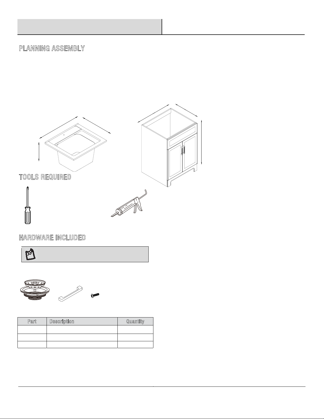
Planning Assembly...................................................................3
Laundry Cabinet Dimensions ..........................................3
Tools Required.........................................................................3
Hardware Included...................................................................3
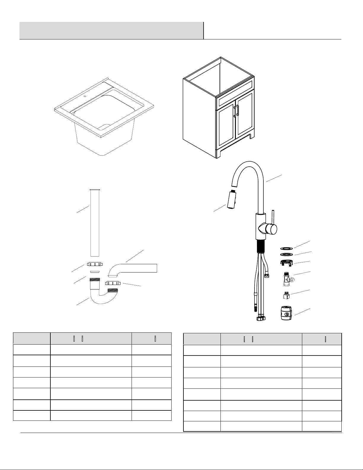
Package Contents ....................................................................4
............................................................................
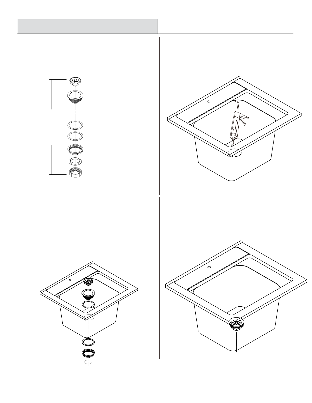
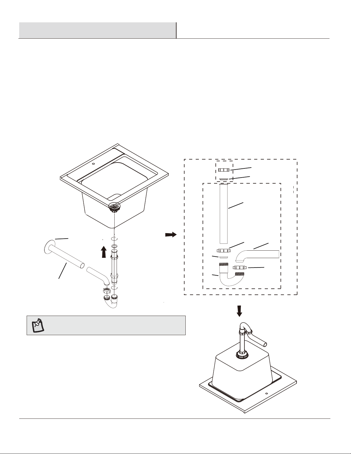
Assembly 5-10
Safety Information
Please read and understand all instructions before assembly and
use.
WARNING: Handle with care. Do not drop or handle
roughly as this will damage the cabinet.
Warranty
12 MONTH LIMITED WARRANTY
The manufacturer warrants this product to be free of material or workmanship defects for a period of 5 years on ceramic and of 1 year on
plumbing components and seat cover, as applicable, following the original purchase.
Damage to product that has been caused by accident, misuse or abuse is not covered by this warranty.
The product is guaranteed for 12 months if used for normal trade purposes. Any warranty is invalid if the product has been overloaded or
subject to neglect, improper use or an attempted repair other than by an authorized agent. Heavy-duty or daily professional/commercial
usages are not guaranteed. Due to continuous product improvement, we reserve the right to change the product specifications without prior
notice.
At our option, we will either have you send the defective part or product at your expense to us for inspection, or we may decide to send you
a replacement component or product without any charge.
Care and Cleaning
□ Clean with a soft cloth using non-abrasive cleaners.
□ Do not place extremely heavy items on the top.
........
..