Dolphin DB 400 Product manual

DB, L, XL 400, 25, 50, 75
DOLPHIN PANEL MOUNTED
INFRARED TAP
INSTALLATION AND MAINTENANCE GUIDE
January 2020
www.divapor.com

2 | Dolphin Blue | DB, L, XL 400, 25, 50, 75 Series
3 Technical Data
4 Pack Contents
5 Pre-Installation Information
7 - 9 Tap Installation
10 - 12 Settings Adjustment
13 Battery Replacement Instructions
14 Maintenance
Filters Cleaning Instructions
Care and Cleaning of Chrome and Special Finishes
15 Spare Parts
16 Limited Warranty
17 Troubleshooting
CONTENTS
www.divapor.com

DB, L, XL 400, 25, 50, 75 Series | Dolphin Blue | 3
TECHNICAL DATA
Wall mounted electronic tap for cold or premixed water
Power Supply
Battery 6x1.5AA battery (DB/L/XL 400 models)
Transformer 9v transformer (DB/L/XL 425 + DB 475 models)
Recommended 0.5-8.0 bar (7-116 PSI)
Water Pressure With water pressure of more than 8 bars use a
pressure reducing valve
Sensor range Self adjusting sensor. Adjustable with remote control
Minimum sensor range 80mm
Maximum sensor range 300mm
Security time 90 seconds Can be changed with the DB51 remote control
Hot water temperature Max 70ºC
www.divapor.com

4 | Dolphin Blue | DB, L, XL 400, 25, 50, 75 Series
PACK CONTENTS
1 x Spout and attachments
(incl. electronic unit)
1 x wall rosette
1 x tubular base
1 x M4 6mm screw
1 x Allen key
1 x filter
DB/L/XL 400
IP67 battery
box
DB/X/XL 425
Transformer
DB, L, XL 400, 25, 50, 75
www.divapor.com

DB, L, XL 400, 25, 50, 75 Series | Dolphin Blue | 5
PRE INSTALLATION INFORMATION
CHECK CONTENTS
› Separate all parts from the packaging and check you have each part according to the
pack contents section, pages 4-6. Pay attention to the variations of the different
models.
› Make sure all parts are accounted for before discarding any packaging material.
› If any parts are missing, do not attempt to install your electronic tap.
Please call 0800 0723 404 immediately to notify us.
WARNING
› To avoid reflection problems keep a distance of
more than 300 mm. between the sink and the
spout.
› This tap model, with an infrared sensor pointing
down, is not intended to be used together with
a sink of a reflective material such as stainless
steel.
› If a sink strainer is straight below the tap sensor,
use a strainer with a non reflective finish (do
not use a chrome plated one).
PREPARATION FOR INSTALLATION
› Flush water supply lines thoroughly before installing the tap.
› Do not allow dirt,Teflon tape or metal particles to enter the tap.
› Shut off water supply.
Important All plumbing is to be installed in accordance with applicable codes and
regulations.
www.divapor.com

6 | Dolphin Blue | DB, L, XL 400, 25, 50, 75 Series
PRE INSTALLATION INFORMATION
WARNING
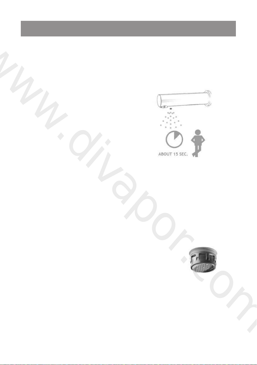
› Highly reflective surfaces directly beneath the sensor of this product, in particular
polished finish basin wastes/ strainers, will cause false activation of the infrared sensors
and can result in malfunction. We recommend satin or matt finish products which
can be found on our website.
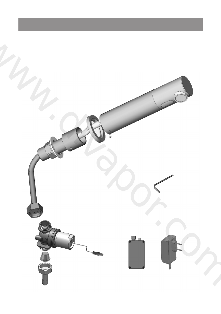
› It is very important to allow permanent access to the mounting tail/nut of this
product for future servicing and repair. Where this is not possible see our wall plate
mounted products.
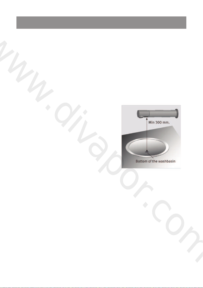
› To avoid reflection problems it is recommended to keep a distance of more than
300mm between the sink and the spout. If the distance is below 300mm a simple
mock-up should be effected to confirm the tap functions as desired in your application
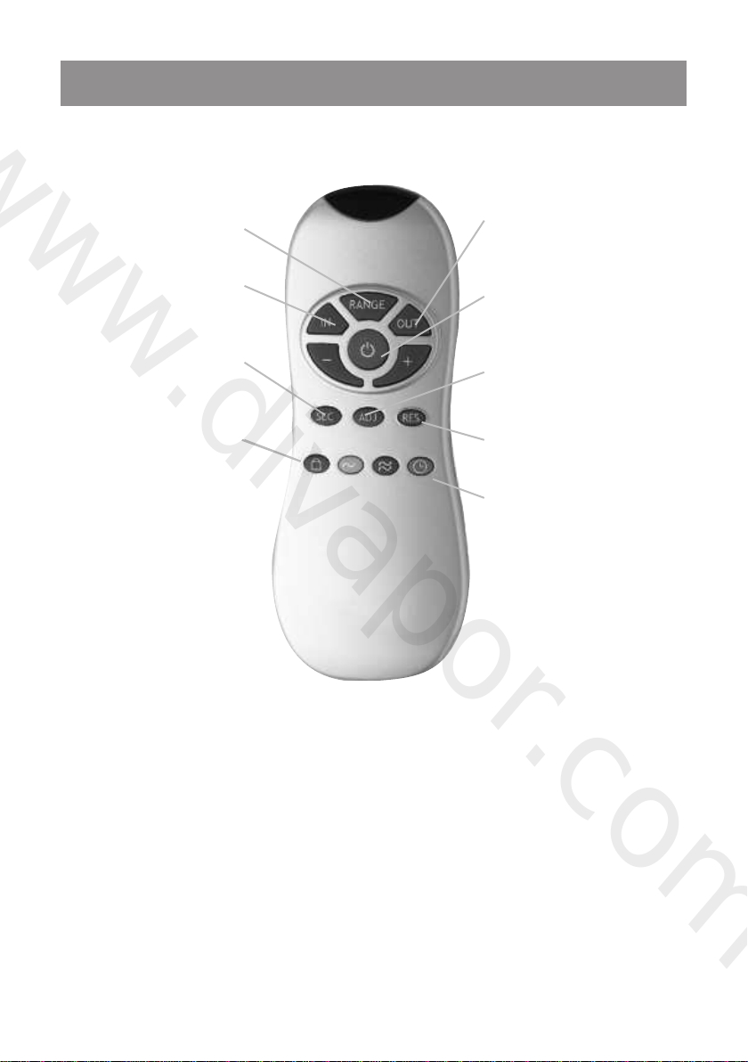
before final installation.You may require a Dolphin Blue remote control to adjust the
range.
› Do not connect water or power supplies or remove the black label covering the nfra-
red sensor until you have read and understood these instructions. Please see page 13.
› It is not recommended to use DB400 series with a polished stainless steel sink. For
this type of application a separate panel-mounted sensor should be used – please
speak to our technical sales team.
› Please observe the guide to minimum cavity depths as shown in the table. This is
important because the water supply hose must not be kinked due to lack of space.
Please note we have provided this information as a guide and cannot be held
responsible for fundamental design
errors. If your situation differs to those
shown below please call us on 0800
0723 404, and we will provide you
with a solution.
Panel Minimum
thickness (A) void (B)
10-15mm 90mm
16-25mm 80mm
26-35mm 70mm
www.divapor.com

DB, L, XL 400, 25, 50, 75 Series | Dolphin Blue | 7
TAP INSTALLATION
INSTALLATION INSTRUCTIONS FOR DB/L/XL 400 + DB/L/XL 425
STEP 1 – INSTALLING THE TAP
1. Shut off the water supply
2. Drill a hole (23 to 24 mm) at the place where you want to install the spout of the
tap.
3. If your model includes an optional anti-rotation pin, drill a small hole just above the
previous one for the anti-rotation pin.
4. Insert the tap and its attachments through the wall.The aerator at the tap spout
must face the washbasin.
5. Insert the anti-rotation pin into the small hole (if needed)
6. Fix the base behind the wall with the hexagonal nut and the disk.
www.divapor.com

8 | Dolphin Blue | DB, L, XL 400, 25, 50, 75 Series
TAP INSTALLATION
STEP 2 – CONNECTING THE WATER SUPPLY
1. Fit the flexible pipe coming from the Tap base
to the solenoid valve housing.
2. Fit the water supply inlet to the adapter at the
solenoid valve housing. Inlet and outlet should
follow the indicating arrow at the solenoid
housing.
Note: Make sure the filter is located at the
solenoid inlet.
3. Connect the cable coming from the electronic unit to the solenoid valve.
Important: Tap was supplied with a Self Adjusting Sensor.The ideal sensor range for
the specific location will be set automatically.
Before proceeding to step 3 check that
no objects are in front of the sensor
besides the washbasin.
Now, remove the protecting
sticker that covers the sensor.
www.divapor.com

DB, L, XL 400, 25, 50, 75 Series | Dolphin Blue | 9
TAP INSTALLATION
STEP 3 – CONNECTING THE POWER SOURCE
1a. For DB/L/XL 400: Connect the other cable
coming from the electronic unit at the Tap
base to the battery box.
1b. For DB/L/XL 425: Connect the other cable
coming from the electronic unit at the Tap
base to the transformer. Plug the
transformer into the electricity socket.
2. After you have connected the power
source (Battery or Transformer) wait 15
seconds in order to allow the system to set
the ideal sensor range.
As an indication that the self adjusting is taking place, a red light in the sensor eye will
flash continuously.The solenoid valve will be opened and closed for 1 second as an
indication that the ideal sensor range was set and the product is ready for use.
3. Turn on the central water supply. Check for leaks.
Note: This tap includes a special aerator that allows you to adjust the water stream
direction on site in order to prevent water splashing if needed.To change the angle
of the water stream, simply move the adjustable tilting
plate by pressing it smoothly.
4. If the automatically adjusted sensor range is not
satisfactory, please refer to the section entitled “Settings
adjustment”.
www.divapor.com

10 | Dolphin Blue | DB, L, XL 400, 25, 50, 75 Series
SETTING ADJUSTMENT
ADJUSTING THE SENSOR WITH THE REMOTE CONTROL
If necessary, the sensor settings can be adjusted as following:
Shut off the water supply. In order to adjust the sensor with the remote control, hold
the remote control straight in front of the sensor in a distance of about 6-8” (15-20cm).
Choose the function you want to adjust by pressing once on one of the function
buttons. After pressing once on a specific function button, a quick flashing of the LED at
the front of the sensor will occur. At this stage, you can change the setting by pressing
the (+) or the (-) buttons, every push will increase or decrease one level. After finishing
the adjustment, turn the water supply back on.
DETECTION
RANGE
DELAY IN
TIME
SECURITY
TIME
LOCK OUT
TIME
DELAY OUT TIME
TEMPORARY OFF
FUNCTION
SELF ADJUSTMENT
MODE
RESET
HYGIENE
FLUSH
www.divapor.com

DB, L, XL 400, 25, 50, 75 Series | Dolphin Blue | 11
SETTING ADJUSTMENT
DETECTION RANGE: This tap was supplied with a Self Adjusting
Sensor.The ideal detection range for the specific location will be set
automatically. Only if necessary, use the remote control to adjust the
sensor range as follows:
Press the RANGE button.Wait until a quick flashing of the red light of
the sensor eye is perceived.Then, press + to increase the one level and
– to reduce it every push will increase or decrease one level.
Note: Once you have changed the detection range with the remote
control, this distance will be remembered by the sensor, even if the
power source is disconnected.To get back to the self adjustment mode,
use the ADJ button only.
ENTRANCE TO THE SELF ADJUSTMENT MODE:
Check that no objects are in front of the sensor. Press the ADJ button.
Once a quick flashing of the red light of the sensor eye is perceived,
remove your hand holding the remote control and move away from the
sensor area.The ideal sensor range for the specific location will be set
automatically. Once the self adjustment has taken place the solenoid
valve will be opened and closed for 1 second as an indication that the
ideal sensor range was set and the product is ready for use.
SECURITY TIME: The Security time, prevents continuous running
of water due to reflections or vandalism. By default, if the sensor
is covered for more than 90 seconds the water flow will shut
automatically. To resume regular operation any obstruction must be
removed.
Press the SEC button.Wait until a quick flashing of the red light of the
sensor eye is perceived.Then, press +to increase the security time and -
to reduce it.
www.divapor.com

12 | Dolphin Blue | DB, L, XL 400, 25, 50, 75 Series
SETTING ADJUSTMENT
DELAY IN TIME: It is recommended to change the delay in time for
flush valves for urinals or toilets only.
If required, the delay intime can also be modified in taps as follows:
Press the IN button.Wait until a quick flashing of the red light of the
sensor eye is perceived.Then, press +to increase the delay in time and
- to reduce it.
DELAY OUT TIME: This button allows modifying the water flow
time after the user removes his hands from the tap.A delay out time
close to 0 will save more water. An increased delay out time will make
the user experience more comfortable.
If required, the delay out time can be modified as follows: Press the
OUT button.Wait until a quick flashing of the red light of the sensor
eye is perceived.Then, press +to increase the delay out time and - to
reduce it.
TEMPORARY OFF FUNCTION: This function is ideal to perform
any kind of activity in front of the sensor without operating the
system (for example, cleaning). The tap will remain shut for 1 minute
when this button is pressed once.To cancel this function and to return
to normal operation press the On/Off button again or wait 1 minute.
RESET BUTTON: This function restores al the factory settings
except for the sensor range. If required, press the Reset button and
without releasing it, press the +button once.
Note: To enter the self adjusting mode, use the ADJ button.
To change the sensor range, use the RANGE button.
www.divapor.com

DB, L, XL 400, 25, 50, 75 Series | Dolphin Blue | 13
BATTERY REPLACEMENT
BATTERY MODELS ONLY
When the battery weakens, the red indicator light will blink at a constant rate when the
user’s hands are within the sensor range.The battery must be replaced within two
weeks.
To replace the battery (battery models only):
For DB/L/XL 400: Open carefully the batteries’ box and remove the old batteries.
Replace the used batteries with six new 1.5V AA batteries. Close the box.
Important: Spent batteries should not be disposed of with normal
household waste. Contact your local authority for information on waste
disposal and recycling.changing the battery.
Check that there are no
objects in front of the sensor
after the battery replacement
was completed.
After you have replaced the battery, move
away from the sensor range.Wait 15 seconds
in order to allow the system to set the ideal
sensor range.Then after the self adjustment has
taken place the solenoid valve will be opened
and closed for 1 second as an indication that
the ideal sensor range was set and the product
is ready for use.
www.divapor.com

14 | Dolphin Blue | DB, L, XL 400, 25, 50, 75 Series
MAINTENANCE
FILTER CLEANING INSTRUCTION
This tap is provided with a stainless steel filter preventing foreign particles to enter
the lines. If the water flow has decreased, this may be because the filter is clogged.
The filter can be cleaned as follows:
For DB/X/XL 400 + 425:
a. Shut-off the water shut off valve.
b. Disconnect the water supply pipe from the adaptor and disassemble the filter
from it.
c. Wash the filter under running water.
d. Reassemble the parts.
e. Restore the incoming water supply.
f. Make sure that there is no water leakage.
CARE AND CLEANING OF CHROME AND SPECIAL
FINISHES
DO NOT use steel wool or cleansing agents containing alcohol, acid, abrasives, or the
like. Use of any prohibited cleaning or maintenance products or substances could
damage the surface of the tap. For surface cleaning of tap us ONLY soap and water,
then wipe dry with clean cloth or towel.When cleaning bathroom tile, the taps should
be protected from any splattering of harsh cleansers.
www.divapor.com

DB, L, XL 400, 25, 50, 75 Series | Dolphin Blue | 15
SPARE PARTS LIST
Self adjusting sensor kit ............................................................................... DB07220239
Solenoid valve kit............................................................................................ DB07230017
Solenoid housing kit for DB/L/XL 400 + 425................................. DB07231008
Transformer ....................................................................................................... DB85M
IP67 Battery box .............................................................................................. DB83M
Diaphragm .......................................................................................................... DB04500001
Optional accessories
Remote control ............................................................................................... DB51
Battery box for 1 x 9v battery ................................................................ DB82M
IP67 Transformer box - unterminated (no plug) ........................... DB69M
Junction Box for up to 10 products...................................................... D87
Transformer junction box exit with 3 meter cable and male connector.
.................................................................................................................................... DB06000084
TMV Mixing valve ........................................................................................... AL0220
www.divapor.com

16 | Dolphin Blue | DB, L, XL 400, 25, 50, 75 Series
Dolphin Solutions Ltd. warrants that its electronic products will be free of defects in
material and workmanship during normal use for two years from the date the product
is purchased.
If a defect is found in normal use, Dolphin Solutions Ltd.. will, at its discretion, repair,
provide a replacement part or product, or make appropriate adjustments. Damage
caused by accident, misuse, or abuse is not covered by this warranty. Improper care and
cleaning will void the warranty. Proof of purchase (original sales receipt) must be
provided to Dolphin Solutions Ltd. with all warranty claims.
Dolphin Solutions Ltd. is not responsible for labor charges, installation, or other
incidental or consequential costs other than those noted above. In no event shall the
liability of Dolphin Solutions Ltd. exceed the purchase price of the product.
If you believe that you have a warranty claim, contact your Dolphin Distributor, Dealer
or Plumbing Contractor. Please be sure to provide all pertinent information regarding
your claim, including a complete description of the problem, the product, model number,
the date the product was purchased, from whom the product was purchased and the
installation date. Also include your original invoice.
DOLPHIN SOLUTIONS LTD. AND/OR SELER DISCLAIM ANY LIABILITY FOR
SPECIAL, INCIDENTAL OR CONSE QUENTIAL DAMAGES.This warranty excludes
product damage due to installation error, incorrect maintenance, wear and tear, battery,
product abuse, or product misuse, whether performed by a contractor, service company,
or the consumer.This warranty does not cover product damage caused by the following:
› Incorrect installation.
› Inversions of supply pipes.
› Pressures or temperatures exceeding recommended limits.
› Improper manipulation, tampering, bad or lapsed maintenance.
› Foreign bodies, dirt or scale introduced by the water supply.
LIMITED WARRANTY
www.divapor.com

DB, L, XL 400, 25, 50, 75 Series | Dolphin Blue | 17
TROUBLE SHOOTING
omin
g
outc
erat
l
y
sontinuouc
sa
PROBLEM OR
T
AT
INDIC
A
1.Sensor flNo w
s
SEAUC
he
UTIONSOL
lighted
ange.rsor’s
ithin the sew
earsandh
ser’swhen u
h oncsaflnot
the sensor d
o
i
n
lighted2. R
et:
auc
fa
f
of
the f
3. R
ange.r
the sensor’s
i
t
e warsandh
ser’swhen u
yg
.ectjbin or another osabhsaw
feflectionsp ring ukicpsSensor i5.
Mode”*rityuin “Secsi4. Unit
puseduelyletompcsiyeratt3. B
oo long.tsange i2. R
-n
e
s
o
e
n
.thoroo stsange i
t
hin .yerattw boL
1. R
toutllu,plenoidew sor
om ther eflectio
n
r
f
aue catElimin
se of
eaclepbe rtsmuyerattThe b
angese the raerDec
angese the raer
Unsc
yeratte baclepR
Inc
er
u
s
p
e
-
n
-s
e
t
ion.
at
h
e
i
f
m
.
n
.
.
t
he
d
e d
r
russe
p
rl
ypp
uer sater wen aev
om drfentsev
pr
k
hecckacthe batth
k
lppuer satse in the waerudden incs
s
aube cldouuation citssThi.higher
et’s
auc
f
russethe pretyand
e in the f
nduse irusseprlyppuer satThe w4.
.ar8 b
hig
h
se irusseprlyppuer satThe w3.
orntsagm ihrapor the diluggedp
a
g
hrape in the dioricalrentThe c2.
ange.r
the sensor’s
ithine warsandh
ser’swhen u
eoncshesafl
in the sensor
light
ed3.
R
.lenoidale in soor scs1. Debri
nderuso
pr
ing,oppr
erussepry
ayb
s
ed
sibody
sarer 8 b
.oductthe prsklocbatth
u
ssee the preduco rder tin or
i
p
le pbix
the fle
f
rsc
ew one of
n
uandlyppuer sat
w
Shut
o
an
h
er th
.resu
e
er pratwlyppue the seducR
s
g
m i
agm.hrapdi
eaclepe or ran the oricleC
i
t
spoalticervinspring ithe s
e t
h
rue sakse male, pngerlup
ing th
e
aclepWhen r.needed
i
aleriater mvemoale rse scU
an the
m
lecandlenoidthe so
omrpring fthe snger andlup
t
outllu,
plenoidew
sorUnsc
hedsdimini
wer float
ange.r
the sensor’s
i
t
e warsandh
ser’swhen u
h oncsaflnot
the sensor d
o
i
n
lighted
:psto
notsdoe
poutom srf
wer float
2. R
ange.rsor’s
ithin the sew
sandhser’su
e whenonc
s
afl
W
W 1. Sensor
loggedcsor iater or aerlt
.ectjbin or another osabhsaw
f
eflectionsp ring ukicpsSensor i2.
t
hin
e
s
o
e
n
.**edervoor ctydirsSensor i1.
operlypredonnectcnot
o
n
sce diarxbouter inpwpothe Dual
o
n
reen the electbetwsoronnect2. C
-n
ear
she
s
agmhrapale in dior scs
Fi
s.ar8 b
pypp
1. Debri
lalte-insan, rlee, cvemo
om ther
f
eflection.r
f
auc
se of
ange or elimi
n
se the raerDec
e.encerferint
se ofae catan or eliminleC
ored
n
nect
andnitu
n
ic
o see
h
age 6 to per tef. Rerly
o
p
prsoronnectthe connectC
agm.hrapdi
eaclepe or ran the oricle
R
p
C
eat
n
.w
h
o
-
p
saubecsondsecerayaywop antslliw wer floatse, the wacs** In thi
age.kloc
b
y
e anvemoation roperalo normrn tuet
or
To
T
y
au
f
sec
. the f
ane th
or mor
f
edervocs
the sensor i
f
rityu* “Sec
Mode
”
:If
f
time.rityu
the sec
f
eof
.wer float
w
hutslyalaticomautlliwet
u
c
o
www.divapor.com

Dolphin Solutions Ltd
Southpoint, Compass Park, Bodiam,
Robertsbridge,TN32 5BS
Tel: +44 (0)1424 20 22 24
Fax: +44 (0)1424 205 200
www.dolphinsolutions.co.uk
www.divapor.com
This manual suits for next models
14
Table of contents
Other Dolphin Bathroom Fixture manuals
Popular Bathroom Fixture manuals by other brands

Gessi
Gessi ANELLO 63469 Bath Mixing Program

Spectrum Brands
Spectrum Brands Pfister Northcott 016-MG0 Quick installation guide

Glacier bay
Glacier bay HD58302-0016 Use and care guide

KERRA
KERRA MOONLIGHT Assembly and maintenance instructions

U-Line
U-Line Simplehuman SH-6094 quick start guide

Presto
Presto DL 300 S installation guide

Better Bathrooms
Better Bathrooms BeBa 27638 user manual

Dudley
Dudley 78810 Installation and user guide

Simpsons
Simpsons DBDSC1060 installation instructions

INDA
INDA BMR02 S quick start guide

Pressalit
Pressalit MATRIX R482619 Operation and maintenance manual

Booth & Co
Booth & Co AXBRIDGE BC-AXB-186-CP installation guide