BC 5083-01 – BC 5083-05 User Manual www.dolphindispensers.co.uk
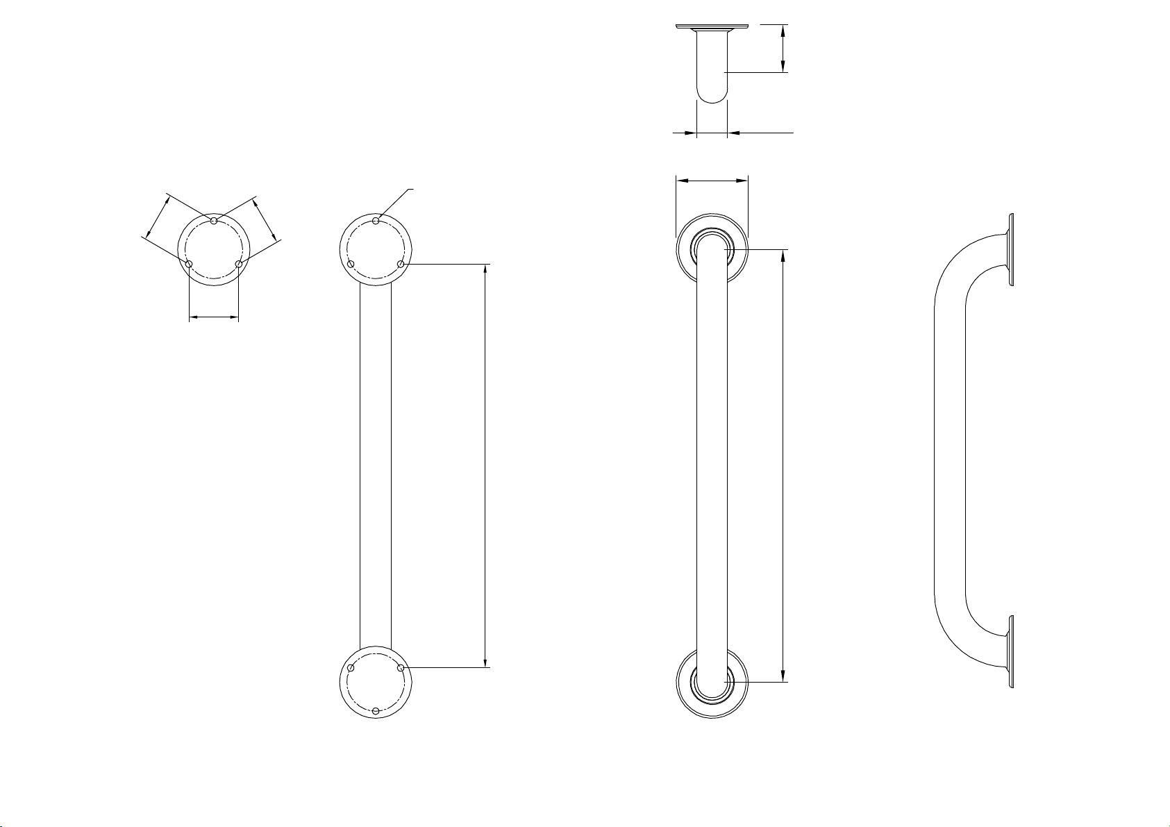
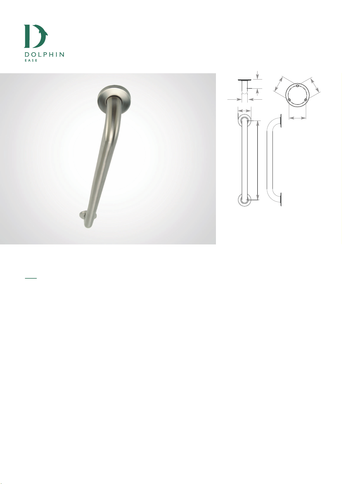
GRAB BAR
SPECIFICATIONS:
Material – 304 Stainless Steel, 1-1/4” O.D. tubing
Includes – Mounting Hardware
INSTALLATION:
1. Grab bars are to be mounted to a secure
surface.
2. Please note all screws must mount firmly into
a wood stud.
3. Place the grab bar on the wall where desired
so that the mounting holes are positioned
over a wood stud.
4. With a pencil, mark the mounting holes’
locations.
5. Remove product from the wall and drill holes
at the marked locations.
6. Mount the grab bar with screw set provided.
7. If mounting a Concealed screw grab bar,
press the cover plate over the grab bar screw
base.
BC5083-01 BC5083-02 BC5083-03 BC5083-04 BC5083-05