Domus BOLT-EM-120-TRIO User manual

29-31 Richland St. Kingsgrove. Sydney NSW 2208 Australia
Phone: 02 9554 9600 | Fax: 02 9554 9433
Installation Manual
Note: -The lamp must be installed by professional electrician
-Ensure the power supply is switched off before fitting this product
-Do not touch the lamp when in use
-Keep away from hot steam and corrosive gas
May 20, 2021
3
3. Fix the batten base onto the required place
with appropriate screws.
6
6.Push caps back to Batten
Base until it catch the spring connector B.
spring connector B
Picture A
BATTEN BASE
LED MODULE
Terminal A
2. Remove Packaging, carefully pull end caps as shown in picture A and gently lift off the LED
module. Disconnect terminal A.
4
4. Connect the live, neutral and earth wires as shown.
(switched active)
Terminal block
L
N
L1
L1
N
L
INPUT CABLE
4X(0.75-2.5mm²)
Outer insulation Inner insulation
30±3mm
8±2mm
(Un-switched active)
1.Disconnect mains supply before installation
or removing cover.
7
7.Reconnect mains supply.
5
5.
To set the colour temperature, simply move the dip switch located at the back of LED module to the desired colour temperature.
Fasten terminal A between driver and LED module. Snap LED module back to batten base. Make sure all Spring Connectors A are in place to
securely hold LED module to batten base.
Terminal A
Terminal B
1
2
3
OFF ON
PIN1 PIN2 PIN3
Power for
40W
OFF ON OFF 20W
ON
OFF ON 30W
OFF
ON ON 40W
Dip switch
5700K/4000K/3000K
Surface Mounted
BOLT-EM-120
Voltage: 240V~ Lumen (±10%):
(10W/40W) Warm White 3000K - 900lm/3600lm
(10W/40W) Neutral White 4000K - 1000lm/4000lm
(10W/40W) White 5700K - 1000lm/4000lm
Dimmable: No
Power: 10/40W CCT: 3000K, 4000K, 5000K Lifespan: 40,000hrs
IP Rating: 44 Beam Angle: 120° Weight: 2.18kg
Frequency: 50Hz CRI: ≥80 Power Factor: 0.9
BOLT-EM-120-TRIO
Order Code Product Code Description
66006 BOLT-EM-120-TRIO Multi Watt and TRIO technology LED batten
Thank you for purchasing your new Bolt Emergency LED Batten, Please take the time to read and understand the instruction sheet below.
Failure to do so may void warranty.
Note: The light source of this luminaire is not replaceable; When the light source reaches its end of life, the whole luminaire shall be
replaced.
Emergency Specification Features
Compliance: Fully complaint to AS/NZS 2293 standards
Battery: LiFePO4 battery type, 6.4V, 7 Hour Charging Time, 1.5 Hours Discharging Time
Battery Capacity: 1500 mAh at 0.2 CmA
Emergency: Sustained
Rated Duration: 90 min
Classification: C0: D50, C90: D32

29-31 Richland St. Kingsgrove. Sydney NSW 2208 Australia
Phone: 02 9554 9600 | Fax: 02 9554 9433
Installation Manual
Note: -The lamp must be installed by professional electrician
-Ensure the power supply is switched off before fitting this product
-Do not touch the lamp when in use
-Keep away from hot steam and corrosive gas
May 20, 2021
Surface Mounted
Warning:
If the product is not installed as per the Installation Manual, then the warranty and liability for the product will be voided.
ALL MAINTENANCE, SUCH AS BATTERY CHANGE ON THIS LUMINAIRE, TO BE PERORMED BY QUALIFIED PERSONNEL
ONLY. DE-ENERGISE ALL SUPPLIES BEFORE MAINTENANCE.
3
3. Fix the batten base onto the required place
with appropriate screws.
6
6.Push caps back to Batten
Base until it catch the spring connector B.
spring connector B
Picture A
BATTEN BASE
LED MODULE
Terminal A
2. Remove Packaging, carefully pull end caps as shown in picture A and gently lift off the LED
module. Disconnect terminal A.
4
4. Connect the live, neutral and earth wires as shown.
(switched active)
Terminal block
L
N
L1
L1
N
L
INPUT CABLE
4X(0.75-2.5mm²)
Outer insulation Inner insulation
30±3mm
8±2mm
(Un-switched active)
1.Disconnect mains supply before installation
or removing cover.
7
7.Reconnect mains supply.
5
5.
To set the colour temperature, simply move the dip switch located at the back of LED module to the desired colour temperature.
Fasten terminal A between driver and LED module. Snap LED module back to batten base. Make sure all Spring Connectors A are in place to
securely hold LED module to batten base.
Terminal A
Terminal B
1
2
3
OFF ON
PIN1 PIN2 PIN3
Power for
40W
OFF ON OFF 20W
ON
OFF ON 30W
OFF
ON ON 40W
Dip switch
5700K/4000K/3000K

29-31 Richland St. Kingsgrove. Sydney NSW 2208 Australia
Phone: 02 9554 9600 | Fax: 02 9554 9433
Installation Manual
Note: -The lamp must be installed by professional electrician
-Ensure the power supply is switched off before fitting this product
-Do not touch the lamp when in use
-Keep away from hot steam and corrosive gas
September20,2021
Installation
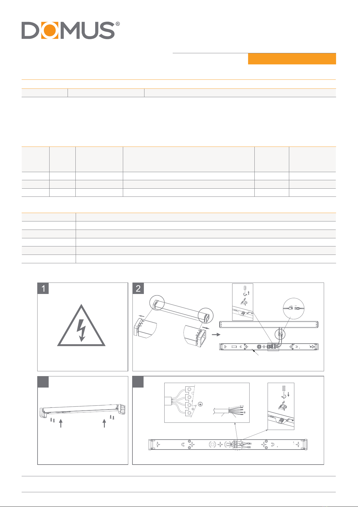
1. Remove the luminaire from its carton and inspect it for damage. If you believe the product to be damaged DO NOT install the product.
Please return it to the place of purchase for a replacement.
2. An emergency sustained luminaire requires two main active supplies. Un-switched active and switched active.
3. The un-switched active is required to charge the batteries. The switched active illuminates the luminaire on mains.
4. Both the switched active and un-switched active must be on the same phase.
5. (For 24/7 operation of the luminaire, link switched active with un-switched active)
6. To ensure maximum battery service life the battery pack is supplied not connected to the emergency luminaire. Before connecting the
emergency luminaire to the mains supply the battery pack must be connected to the emergency inverter via the polarized plug fitted
to the battery pack.
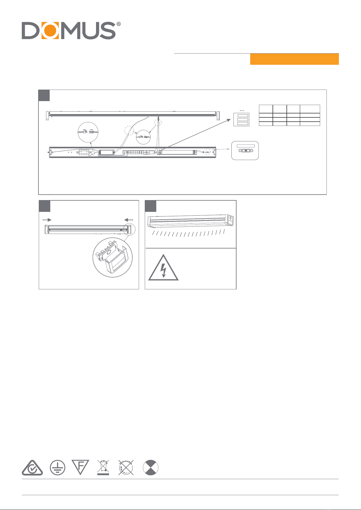
7. To ensure maximum product service life and performance, mount the emergency luminaire away from any direct heat source where the
ambient temperature exceeds 40 deg. C.
8. To check the correct operation of the luminaire, allow the battery to charge for a minimum of 3 minutes, ensuring that the green
charging LED is constantly illuminated. Depressing the test switch will then illuminate the emergency LED light.
9. Discharge time for 90 minute.
10. The product has an indicator light, the test button is used to detect whether the lamp is operating normally, and when press the test
button, the luminaire is in emergency mode; when release the test button, the battery is charged.
11. When the battery is charged, the green indicator light on; when the battery is fully charged, the green indicator light is on, when the
luminaire is in emergency mode, the indicator light will extinguish.
12. Emergency light source:>410 lm, CCT: 6500K.
Testing procedure
When the Stellar V EMG Batten is permanently connected to the mains allow 24 hours to fully charge the batteries. Once the batteries
are fully charged the emergency luminaire is required to undergo a commissioning discharge test to confirm compliance as specified
in Australian Standard AS2293 part 2. The emergency luminaire must operate for a minimum of 2 hours in emergency mode. Further
compliance testing is required at intervals of not more than six months, however for these tests the emergency luminaire must operate
for a minimum of 90 minutes in emergency mode.AS2293 part 2 also sets out the mandatory requirements of recording of all tests and
their results, plus any maintenance actions carried on the emergency luminaires. Energetic Lighting has available an emergency lighting
maintenance LOG book for recording of this information.
Problem Solving
If you have installed and connected the Stellar V EMG Batten and the product fails to work properly, please use the following table as a
starting guide to solve the issue.

29-31 Richland St. Kingsgrove. Sydney NSW 2208 Australia
Phone: 02 9554 9600 | Fax: 02 9554 9433
Installation Manual
Note: -The lamp must be installed by professional electrician
-Ensure the power supply is switched off before fitting this product
-Do not touch the lamp when in use
-Keep away from hot steam and corrosive gas
September20,2021
Construction site issues that may affect product performance and service life.
IMPORTANT NOTE: Continuously switching the power supply to the emergency luminaire during or after the installation could cause
the emergency luminaire to discharge its battery. This can impact negatively on the battery service life. It is not recommended that any
emergency lighting product be connected to the power supplyif such conditions are prevalent. Exposure of the emergency lighting products
to harsh operating conditions may result in the product warranty being voided.
Fault Possible cause of fault Solution
Green charge indicator LED is not lit a) AC Supply is not connected
b) AC Supply is switched off
c) AC Supply is on a switched active circuit, but the
switched active circuit is switched off
Connect AC Supply Switch on AC supply
Change to un-switched active AC supply
Green charge indicator LED is lit
but the emergency LED does not
illuminate when the test switch is
depressed
a) Emergency LED or inverter is damaged
b) Battery is damaged
c) Battery is not connected to the emergency
inverter.
Replace luminaire Replace battery pack
Connect battery pack
Emergency LED illuminates, but
only temporarily when test switch
is pressed or when the main power
supply is turned off
a) Battery not fully charged
b) Battery pack is damaged
Allow battery to charge for 24 hours and
re-test Replace battery pack
This manual suits for next models
1
Other Domus Lighting Equipment manuals
Popular Lighting Equipment manuals by other brands

Portfolio
Portfolio 00990 quick start guide

GRE
GRE AR-110 installation instructions

Thrive Energy Technologies
Thrive Energy Technologies ACCENDO FAQs on Maintenance and Repairs

Sonoff
Sonoff L1-2M user manual

thomann
thomann STAIRVILLE BEL1 Battery Event Light 15W user manual

Saxby Lighting
Saxby Lighting Flexline 73670 Instruction leaflet