DoorHan DCUT-1 User manual

CONTROL UNIT
DCUT-1 TELESCOPIC LIP DOCK LEVELLER
© DooHan, 2015
Original installation and operation instruction
GENERAL INFORMATION 2
SAFETY RULES 3
GENERAL VIEW 3
ELECTRICAL CONNECTIONS 4
OPERATING 6
APPENDIX 7

2
CONTENT
CONTENTS
1. General information .............................................................................2
1.1. Technical data ..............................................................................2
2. Safety rules ....................................................................................3
3. General view ...................................................................................3
3.1. Front panel .................................................................................3
4. Electrical connections ............................................................................4
4.1. Control unit diagram .........................................................................4
4.2. Control unit connection .......................................................................5
4.3. Connection of safety devices ...................................................................5
5. Mounting ......................................................................................6
6. Operation .....................................................................................6
6.1. Operation ..................................................................................6
6.2. Return to initial position .......................................................................6
6.3. Emergency stop .............................................................................6
7. Appendix ......................................................................................7
7.1. Connection dock leveller and control unit ..........................................................7
7.2. Spare parts .................................................................................7
FUNCTION
Function DCUT-1 DCUT-2 DCUT-3
Impulse AUTO button
400Volt
Traffic light outside
Traffic light inside
Dock light
Interlock (door-dockleveler)
Extra safety devices connection
Service indicator
Digital display
Door control
Inflatable dock shelter control
1. GENERAL INFORMATION
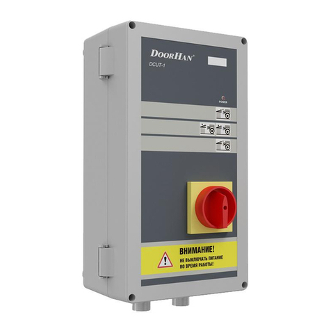
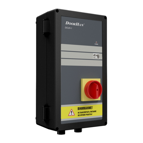
DCUT-1 control unit has designed for telescopic lip dock leveller operating.
Compatible with DoorHan dock levellers serie DLHT, DS, DSI.
Control unit equipped with protection system of uncontrolled motion in case of power failure.
Quick connectors provide easy installation.
Cables for connection of control unit with dock leveller supplied with dock leveller.
MANUFACTURER’S DECLARATION OF CONFORMITY
Manufacturer: LLC StoreHan, 143002, Russia, Moskovskaya obl., Odintsovskij r-n, s. Akulovo, ul. Novaya, d. 120
Trademark: DoorHan
Cotrol units for dock levellers with hinged lip and dock levellers with telescopic lip
series DCUH-1/2/3 and DCUT-1/2/3 fulfil the stipulations of the Directive 2006/95/EC Low-voltage, 2004/108/EC Electromagnetic
compatibility to the following standarts EN ISO 12100:2010, EN 1398:2009, EN ISO 1570-1:2011+А1:2014, EN 60204-1:2006/
А1:2009/Cor.Feb.:2010, EN 61000-6-2:2005/Corr.Sep.:2005, EN 61000-6-4:2007/A1:2011
This declaration of conformance is not applied if:
the Product is operated in the extreme climatic conditions, in the magnetic action environment etc, and in case of special
requirements, e.g. explosion hazard;
the Product is operated for loading/unloading of hazardous substances e.g. acids, radiation-emitting materials, molten
metal, fragile freights;
the risk arises caused through transport facilities (e.g. forklift etc).
3
GENERAL VIEW
1.1. TECHNICAL DATA
Parameter Value
Power supply 400 V/50 Hz
Connection valves 1 х 24 V DC, 20 Va
Hydraulic unit 1.1 kW
Working temperature range –10… +55°C
Overall dimensions (whd) 280180130 mm
Protection IP 54
• The mains voltage must correspond to power supply of control unit
3. GENERAL VIEW
3.1. FRONT PANEL
1. Power indicator
2. Button lip pull out
3. Button down
4. Button up
5. Button lip pull in
6. Main switch
DCUT-1
1
2
4
5
3
6
2. SAFETY RULES
WARNING! Follow all the instructions manual, since improper installation of equipment can lead to serious damage
and injury.
The improper use is not allowed.
Installation, settings and maintenance of this equipment can only be performed by qualified personnel with corresponding
permit in accordance with relevant manufacturer’s instructions.
Before operating the control unit, make sure that all electrical connections are secure and isolated, all control voltage
inputs are galvanically isolated from the supply.

4
ELECTRICAL CONNECTIONS
4.1. CONTROL UNIT DIAGRAM
4. ELECTRICAL CONNECTIONS
WARNING! Prior to electrical mounting works on connecting the control unit it is necessary to cut off electric power
supply and provide its absence during these works.
L1 L2 L3 L3* N* NPEPE V WU
Трансформатор Реле
защиты
Контактор
7 8 9 10
КАТУШКИ ЭЛЕКТРОМАГНИТНЫХ
КЛАПАНОВ
OUT1
+24
OUT2
+24
OUT3
+24
КАТУШКИ ЭЛЕКТРОМАГНИТНЫХ
КЛАПАНОВ
OUT1
123456
+24
OUT2
+24
OUT3
+24
КОНЦЕВОЙ ВЫКЛЮЧАТЕЛЬ
МЕХАНИЧЕСКИЙ
7 8 9 10 7 8 9 10
КОНЦЕВОЙ ВЫКЛЮЧАТЕЛЬ
МЕХАНИЧЕСКИЙ
M
МОТОР ГИДРОСТАНЦИИ
NPE
N
400 V
L1 L3L2PE
Hydrauliс unit motor
Transformer
Contactor
Protection relay
Valves
400 V
Interlock

5
ELECTRICAL CONNECTIONS
L1 L2 L3 L3* N* NPEPE V WU
Трансформатор Реле
защиты
Контактор
7 8 9 10
КАТУШКИ ЭЛЕКТРОМАГНИТНЫХ
КЛАПАНОВ
OUT1
+24
OUT2
+24
OUT3
+24
КАТУШКИ ЭЛЕКТРОМАГНИТНЫХ
КЛАПАНОВ
OUT1
123456
+24
OUT2
+24
OUT3
+24
КОНЦЕВОЙ ВЫКЛЮЧАТЕЛЬ
МЕХАНИЧЕСКИЙ
7 8 9 10 7 8 9 10
КОНЦЕВОЙ ВЫКЛЮЧАТЕЛЬ
МЕХАНИЧЕСКИЙ
M
МОТОР ГИДРОСТАНЦИИ
NPE
N
400 V
L1 L3L2PE
L1 L2 L3 L3* N* NPEPE V WU
Трансформатор Реле
защиты
Контактор
3 4 5 6
КАТУШКИ ЭЛЕКТРОМАГНИТНЫХ
КЛАПАНОВ
OUT1
+24
OUT1
12
+24
КОНЦЕВОЙ ВЫКЛЮЧАТЕЛЬ
МЕХАНИЧЕСКИЙ
3 4 5 6
M
МОТОР ГИДРОСТАНЦИИ
NPE
N
400 V
L1 L3L2PE
L1 L2 L3 L3* N* NPEPE V WU
N
400 V
L1 L3L2PE
L1 L2 L3 L3* N* NPEPE V WU
МОТОР ГИДРОСТАНЦИИ
NPE
12
M
L1 L2 L3 L3* N* NPEPE V WU
Трансформатор Реле
защиты
Контактор
3 4 5 6
КАТУШКИ ЭЛЕКТРОМАГНИТНЫХ
КЛАПАНОВ
OUT1
+24
OUT1
12
+24
КОНЦЕВОЙ ВЫКЛЮЧАТЕЛЬ
МЕХАНИЧЕСКИЙ
3 4 5 6
M
МОТОР ГИДРОСТАНЦИИ
NPE
N
400 V
L1 L3L2PE
L1 L2 L3 L3* N* NPEPE V WU
N
400 V
L1 L3L2PE
L1 L2 L3 L3* N* NPEPE V WU
МОТОР ГИДРОСТАНЦИИ
NP
E
12
M
Power pack connection provided with fast connection cable.
3 phase 400 V 1.2 kWtt max.
4.3. CONNECTION OF SAFETY DEVICES
Limit switch.
4.2. CONTROL UNIT CONNECTION
Power supply 5x1.5 mm2 cable.
Solenoid coils connection provided with fast connection
cable. 1x24 V DC.
In case when safety devices are not in use.
L1 L2 L3 L3* N* NPEPE V WU
Трансформатор Реле
защиты
Контактор
3 4 5 6
КАТУШКИ ЭЛЕКТРОМАГНИТНЫХ
КЛАПАНОВ
OUT1
+24
OUT1
12
+24
КОНЦЕВОЙ ВЫКЛЮЧАТЕЛЬ
МЕХАНИЧЕСКИЙ
3 4 5 6
M
МОТОР ГИДРОСТАНЦИИ
NPE
N
400 V
L1 L3L2PE
L1 L2 L3 L3* N* NPEPE V WU
N
400 V
L1 L3L2PE
L1 L2 L3 L3* N* NPEPE V WU
МОТОР ГИДРОСТАНЦИИ
NPE
12
M
400 V
Hydrauliс unit motor
Valves

6
CONTROL UNIT OPERATION
6. CONTROL UNIT OPERATION
6.1. OPERATING.
Turn the main switch to «I» position.
Check that the control unit power indicator lights, then press up button for lifting of dockleveler.
Keep the button pressed until complete lifting of DL. Then press button lip pull out and keep it pressed untill the extension of lip
becomes required length.
Press down button briefly and wait while the lip will come down to the truck body.
WARNING! Don’t switch off power while dockleveler is being used. Only in case of emergency. Emergency stop
function integrated into the main switch. Use this function ONLY in case of emergency. It may not be used during
loading/unloading, as the dock leveller is unable to follow the vertical movements of truck which could lead to damage
of hydraulic system.
6.2. RETURN TO THE INITIAL POSITION
After finish of loading/unloading dock leveler has to back to initial position.
Press up button and lift dockleveler approx. 100mm higher from truck body.
Press and keep lip pull in button while the lip is not retract completely. Press down button briefly, dock leveler descend to park
position position. Turn off main switch to “0”.
6.3. EMERGENCY STOP
In case of emergency turn the main switch to «0»
To resume dock leveler operation, make sure that the power is on, there is nobody under the deck or close to dockleveler movable
parts. Press up button briefly.
Recomended height of control unit mounting 1…1,5 m
Fasteners choosen depending on the type of wall.
5. MOUNTING
Fix points

7
APPENDIX
Fast connection cables
№ Item Leight, m Article
3 Fast connection cable for DCUT-1,2,3 7 DKTL02
4 Fast connection cable for DCUT-1,2,3 10,5 DKTL02-1
Spare parts
№ Item Article
1 Top cover DCUH/T DCU001
2 Control board DCUT-1 DCU004
3 Main board DCUT-1 DCU003
4 Main switch DCU002
5 Bottom cover DCUH/T DCU002
6 Sticker DCUT-1 NDCUT-1
A
B
C
D
E
R
S
T
U
V
1 32 4 13 14 15 16
121110987654321
A
B
C
D
E
F
G
H
J
K
L
M
N
P
Q
C BP1 A
7L.
PHC1.7 cc/rev
120
24VRAC
130
24VRAC
1.2mm
24VRAC
90µm
1 2 3 4 5 6
MV1 MV2 MV3
1
2
4
3
Ïîäêëþ÷åíèå êàòóøåê
ñîëåíîèäîâ
1 2 3 4 5 6
MV1 MV2 MV3
M
LOGICVALVEWITH
CHECK VALVE
1.1KwTR.
230/400 Kw50Hz
3
2
1
3
2
1
A
B
C
D
E
R
S
T
U
V
1 32 4 13 14 15 16
121110987654321
A
B
C
D
E
F
G
H
J
K
L
M
N
P
Q
C BP1 A
7L.
PHC1.7 cc/rev
120
24VRAC
130
24VRAC
1.2mm
24VRAC
90µm
1 2 3 4 5 6
MV1 MV2 MV3
1
2
4
3
Ïîäêëþ÷åíèå êàòóøåê
ñîëåíîèäîâ
1 2 3 4 5 6
MV1 MV2 MV3
M
LOGICVALVEWITH
CHECK VALVE
1.1KwTR.
230/400 Kw50Hz
3
2
1
3
2
1
Valves connection.
7. APPENDIX
7.1. CONNECTION DOCK LEVELLER AND CONTROL UNIT
Connection of dock leveller and control unit provided by fast connection cable. The length of cable choosing depending on the
place of control unit installation and the lengs of dock leveller.
7.2. SPARE PARTS
4
1
6
5
3
2

The company DoorHan thanks you for buying our products.
We hope you will be satisfied with the quality of our product.
If you need any further information about purchasing, distribution and maintenance,
contact our regional agents or refer to our central office to the following address:
Russia, 143002, Moscovskaya oblast, Odintsovskiy r-n,
s. Akulovo, ul. Novaya, 120.
Tel: +7 (495) 933-2400, 981-1133
E-mail: [email protected]
www.doorhan.com
This manual suits for next models
2
Table of contents
Other DoorHan Control Unit manuals

DoorHan
DoorHan GC4 Operating instructions

DoorHan
DoorHan CV01 Operating instructions

DoorHan
DoorHan DCUH-2 User manual

DoorHan
DoorHan DCUT-1 User manual

DoorHan
DoorHan DCUT-1 User manual

DoorHan
DoorHan DCUH-1 User manual

DoorHan
DoorHan PCB-SH Installation manual

DoorHan
DoorHan DCUH-1 User manual

DoorHan
DoorHan GC2 Operating instructions

DoorHan
DoorHan DCUH-1 User manual