manuals.online logo
Brands
  1. Home
  2. •
  3. Brands
  4. •
  5. DoorKing
  6. •
  7. Gate Opener
  8. •
  9. DoorKing 9150 Series User manual

DoorKing 9150 Series User manual

4910 4910
REVERSE
SENSITIVITY
REVERSE
LOOP
EXIT
LOOP
KEY SWITCH
DOORKING
4602-010
SW1 SW2
OPEN
TIMER
WARNING
MOVINGGATE CAN CAUSE
Operategate only when gate areais in sight
andfreeof people and obstructions.
Donot allow children to playin gate area
oroperate gate.
Donot stand in gate path or walk through
pathwhile gate is moving.
Readowner’s manual and safety instructions.
SERIOUSINJURY OR DEATH
CLASS
CERTIFIEDTO
CAN/CSAC22.2 NO. 247
CONFORMSTO
ANSI/UL-325
VEHICULARGATE OPERATOR
HP
53382
MODEL
SERIAL
VOLTS PHASE
AMPS 60Hz
MAXGATELOAD
DoorKing,Inc., Inglewood, CA
ON
ON
REVERSE
SENSITIVITY
REVERSE
LOOP
EXIT
LOOP
KEYSWITCH
DOORKING
4602-010
SW1 SW2
OPEN
TIMER
NC
1
2
3
4
5
NO
2.5”
Concrete Pad Center
14.5”
Conduit Area
Electronic Box
8.5”
QUICKSTART “BASIC” GUIDELINES FOR MODEL 9150 - FRONT INSTALLATION MOUNTED ON A CONCRETE PAD
Model 9150 is intended for installation only on sliding gates used for vehicles.
Pedestrians must be supplied with a separate access opening. For safety and installation instructions, please refer to the Installation/Owner’s manual.
Copyright 2016 DoorKing, Inc. All rights reserved. 9150-066-H-5-16
Concrete pad
MUST be level!
This depth of the concrete pad is
determined by soil conditions and
local building codes (reinforced
concrete recommended).
Loosen the 2 nuts under the
electronic box to swing box up.
Use 3/4-inch conduit
with sweeps.
Use (4) 3/8” x 2”
Sleeve Anchors
(Not supplied).
Loop Conduit
AC Power
Conduit
4” minimum
above ground.
Opening
Direction
Switch 1 OFF.
21.5” Minimum
26” Minimum
Idler
Wheel
Use existing
wire restrainers
to keep wire
away from
moving
parts.
Concrete Pad
• Chain MUST be parallel to gate!
• Chain bracket MUST line up with
idler wheels!
Chain brackets
MUST be mounted
the same height as
the chain on the
idler wheels!
Chain
Bracket
SW 1
12345678
ON
Opening
Direction
Switch 1 ON.
SW 1
12345678
ON
B
B
A
C
High Voltage Connection
Tip: It is recommended that a surge suppressor be
installed on the high voltage power lines.
GATE OPERATOR MUST BE PROPERLY GROUNDED!!
The 9150’s open/close limits DO NOT have to be
physically adjusted. Every time the 9150 is powered
up, the first open command will automatically run
“2 open/close gate cycles” that will locate and
remember the gate’s open and close limit
positions. These limit positions are determined by
where the physical stops have been installed. It does
not matter what position the gate is in before
running this sequence. The gate will function
normally after this automatic sequence
has finished.
Adjust the chain nuts to tighten the chain.
The chain should sag no more than one
(1) inch per 10 feet of chain travel.
Do not over tighten the chain.
Automatic Limits
Chain Adjustment
Note: Auto-close timer should be
on before running this sequence.
Chassis Ground
White - Neutral
Black - 115 VAC Hot
Green - Chassis Ground
Hot Neu
Every time the 9150 is powered up, the First open
command will automatically run “2 open/close gate
cycles” that will locate and remember the gate’s open
and close limit positions. See “Automatic Open/Close
Limit Adjustment” in Installation/Owner’s manual for
more information.
1” minimum space between the gate and the operator housing.
21.5”
Min.
26” Min.
Concrete Pad and Conduit Area
Circuit Board Settings
ON
12345678
SW 2
ON
12345678
SW 1
1. Opening Direction (See Illustration)
2. ON
3. OFF
4. OFF
5. OFF
6. OFF
7. OFF
8. OFF
1. ON
2. OFF
3. OFF
4. OFF
5. OFF
6. OFF
7. OFF
8. OFF
Auto-Close Timer
Adjust 1 to
23 sec.
123
Note: SW 2, switch 1 is
turned on when plug-in
exit loop detector is
installed.
SW 1, Switch 1 - Must OPEN the gate upon initial AC
power up and open command. If the open command
begins to close the gate, turn AC power off and
reverse this switch. (See reverse side)
“Basic” Setting of DIP-Switches
OPEN
TIMER
Cycles the operator
when pressed.
Key Switch
Warning Signs
High Voltage
AC Power Wire
B
Radio Receiver
CNot included - Refer to a specific Radio Receiver
Manual (available from www.dkaccess.com) for
more information on radio receivers and antenna
installation. (See reverse side for wiring)
Plug-In Loop Detectors
Not included - Refer to the Installation/Owner’s
manual AND Loop Information Manual (available from
www.dkaccess.com) for more information on loops
and plug-in loop detectors.
Important Note: DoorKing highly recommends that
loops and loop detectors are installed with this slide
gate operator. A loop detection system will preventing
the gate from automatically opening or closing on a
vehicle when it is in the gate’s path.
DO NOT power up and cycle the operator without “Physical Stops” installed
to stop the gate in the open and close positions, (Chain stops are included with
the operator but other physical stops can be used) damage could occur to the
gate and operator. Chain stop’s rubber
bumpers face toward
operator. They will make
contact with the operator
housing during the initial
automatic open/close
limits setting
sequence.
Physical Stops MUST be Used to Stop Gate
Anti-
Grounding
Plate
Connect Chain
Bracket
and
Chain
to Gate
Chain
Nut
Chain
Bolt
Option 2
Master
Link
Option 1
Gate
Frame
Chain nut and
chain bolt should not
protrude past gate frame.
Wire
Restrainer
Power safety and opening devices
that require 115 VAC power.
Two 115 VAC Convenience Outlets
Note: “Optional” High
Voltage Kit black and
white wires connect
the same as shown.
See High Voltage Kit
instruction sheet for
more information.
115 VAC
AC Power Terminal
DANGER
HIGH VOLTAGE!
120 S. Glasgow Avenue
Inglewood, California 90301
U.S.A.
At least ONE external
entrapment protection
device MUST be installed
or the operator will NOT
function. See reverse side
Permanently mount signs on BOTH sides of the
gate area and make sure they are easily visible.
ON
ON
REVERSE
SENSITIVITY
REVERSE
LOOP
EXIT
LOOP
FULL OPEN
DOORKING
4602-010
SW1
SW3
SW2
OPEN
TIMER
NC
NO
1
2
3
4
5
6
7
8
9
10
1
ON
2 3 4
UL 325 LEDs
18
17
16
15
14
13
12
11
10
9
8
7
6
5
4
3
2
1
Full Open
Common
Common
Full Open
FULL
ULL
24 V Power
Partial Open
SW 1
SW 2
7-OFF
7-OFF
7-ON
7-ON
8-OFF
8-ON
8-OFF
8-ON
Gate Open
Back-Off
Position
Normal Setting. Gate fully opens.
Gate stops short 1” from full open position. Used for a reversing edge device.
Gate stops short 2” from full open position. Used for a reversing edge device.
Gate stops short 3” from full open position. Used for a reversing edge device.
Switch Function Setting Description
OFF
ON
4-OFF
4-OFF
4-ON
4-ON
5-OFF
5-ON
5-OFF
5-ON
Auto-Close
Timer
Relay Activation
and
LED Indicator
Light Activation
2
1
Motor
Hold
OFF
ON
3
4 and 5
7 and 8
Normal Setting. No voltage to motor when gate is stopped (Level gate).
Voltage applied to motor always. Keeps inclined gate from coasting when stopped.
Auto-close timer is OFF. Manual input required to close gate.
Auto-close timer is ON. Adjustable from 1-23 seconds to close gate.
OFF
ON
Self-Test
6Normal Setting.
Runs self-test. Caution: Bench testing ONLY!
Relay activates and LED is ON when the gate is fully open.
Relay activates and LED is ON when the gate is not closed.
Relay activates and LED is ON when the gate is opening and open.
Relay activates and LED is ON when the gate is opening and closing.
Changes the direction the operator will open/close the gate depending on the different chain configurations.
Opening
direction
using OFF
setting.
Opening
direction
using ON
setting.
Post
Mounts
Center or
Opens
with
ON
setting.
Mounts
Right
All Rear
Opens
with
OFF
setting.
Mounts
Left
All Rear
Opening
direction
using ON
setting.
Opening
direction
using OFF
setting.
Mount
Front
ON
12345678
SW 2
ON
12345678
SW 1
OFF
ON
Operator Model
Select
5
7-OFF
7-OFF
7-ON
7-ON
8-OFF
8-ON
8-OFF
8-ON
Gate Close
Back-Off
Position
Normal Setting. Gate fully closes.
Gate stops short 1” from full close position. Used for a reversing edge device.
Gate stops short 2” from full close position. Used for a reversing edge device.
Gate stops short 3” from full close position. Used for a reversing edge device.
Switch Function Setting Description
2
7 and 8
Built-in
Solenoid
Lock
OFF
ON
4
Normal Setting. Fail-safe logic. Lock engages only if attempt is made to force gate
open (Factory setup).
Fail-secure logic. Lock engages after each gate cycle (2600-865 Lock kit required).
Normal Setting. Switch must be OFF for Model 9150.
DO NOT use ON setting for Model 9150.
OFF
ON
Partial Open
(14 Ft)
3Normal Setting. Switch must be OFF for terminal #5 input to open gate 14 Ft.
DO NOT use ON setting. NOT associated with partial open feature for the 9150.
OFF
ON
OFF
ON
Normal Setting. Input to terminal #6 and/or reverse loops will reverse gate
during close cycle.
Input to terminal #6 and/or reverse loops will stop gate during close cycle – gate
will continue to close after input to terminal #6 and/or reverse loops are cleared
(Helps prevent tailgating vehicles from unauthorized entry).
OFF
ON
6
Normal Setting. Timer will function normally.
Opening gate will stop and begin to close as soon as all reversing inputs (Reverse
loops, photo sensors) are cleared regardless of the distance the gate has opened.
1
Quick-Close
Timer Override
Exit Loop Port
Output
Full Open Input
A plug-in exit loop detector plugged into the EXIT Loop port will partially open single
operator or fully open dual operators depending on type of loop detector used).
Normal Setting. Plug-in exit loop detector will fully open gate (Single operator).
Reverses Gate
Stops Gate
WARNING
MOVINGGATE CAN CAUSE
Operategate only when gate area is in sight
andfree of people and obstructions.
Donot allow children to play in gate area
oroperate gate.
Donot stand in gate path or walk through
pathwhile gate is moving.
Readowner’s manual and safety instructions.
SERIOUSINJURY OR DEATH
CLASS
CERTIFIEDTO
CAN/CSAC22.2 NO. 247
CONFORMSTO
ANSI/UL-325
VEHICULARGATE OPERATOR
HP
53382
MODEL
SERIAL
VOLTS PHASE
AMPS 60Hz
MAXGATE LOAD
DoorKing,Inc., Inglewood, CA
ON
ON
REVERSE
SENSITIVITY
REVERSE
LOOP
EXIT
LOOP
KEYSWITCH
DOORKING
4602-010
SW1 SW2
OPEN
TIMER
NC
1
2
3
4
5
NO
Red Full Open
Green Close
White Com
Key Switch
Stand-Alone
Keypad
Stand-Alone
Card Reader
Telephone
Entry
Fire Box
3-Button
Control Station DoorKing ONLY
Note:
All stand-alone
and telephone
entry devices
must use a
separate power
source.
#4-Connected device fully opens gate.
#5-Connected device opens gate 14-feet.
#2-Full Open
Com
Com
Com
Relay - #2 - Full Open.
#5 - Opens gate 14-feet.
Relay N.O. - #2 - Full Open.
#5 - Opens gate 14-feet.
250 mamp.
max.
3-Wire Radio Receiver
ON
12345678
SW 2
SW 2,
switch 3
must be
OFF.
Relay Com
24 Volt Com
24 Volt - 250 mamp. max.
4-Wire
Receiver
#5 Terminal Note (Single
Operator Only): Any opening
device connected to terminal #5 will
open the gate to the partial open
14-ft setting. External entrapment
protection devices will also open the
gate to the partial open setting. If the
Inherent Reverse Sensor gets
activated during the close cycle, it
will always fully open the gate.
24 volt
Note: After a DIP-switch setting is changed, power must be turned OFF and then turned back on for the new setting to take affect.
Jumper Wire
Needed
See Manual
Important: Controls intended for user activation must be located at least six (6) feet away from any moving part
of the gate and where the user is prevented from reaching over, under, around or through the gate to operate the
controls. Emergency access controls only accessible by authorized personnel (e.g., fire, police, EMS) may be
placed at any location in the line-of-sight of the gate.
N
C
UL 325
Terminal
UL 325
DIP-Switches
Closed Gate
Wall
Close Beam
Open Beam
Filler Post If necessary
Open Edge
IMPORTANT: Photo sensors
must use Normally Closed (NC)
contacts with the beam set for
light operate (relay activated
when beam is not obstructed).
External Entrapment
Protection Devices
IMPORTANT: Only 1 monitored Device can be connected
to each input. An OPTIONAL Expansion Kit (sold
separately) will allow connection for additional devices.
UL 325 Terminal
Close Edge
Open Edge
DIP-switches MUST be turned ON for each device wired to terminal.
At least ONE external
entrapment protection
device MUST be installed
or the operator will NOT
function.
UL 325 DIP-Switches
N.C.
N.C.
N.C.
N.C.
N.C.
Connect ONLY MONITORED
Devices
1
ON
2 3 4
1 - OPEN Beam STOP
2 - Ground (Common)
3 - CLOSE Beam REVERSE
4 - Ground (Common)
5 - 24 VAC 250 ma. Max
6 - Ground (Common)
7 - OPEN Edge/Beam REVERSE
8 - Ground (Common)
9 - CLOSE Edge/Beam REVERSE
10 - Ground (Common)
1 - OPEN Beam (UL 325 Terminal 1)
2 - CLOSE Beam (UL 325 Terminal 3)
3 - OPEN Edge (UL 325 Terminal 7)
4 - CLOSE Edge (UL 325 Terminal 9)
(See Installation/Owner’s manual for more information)
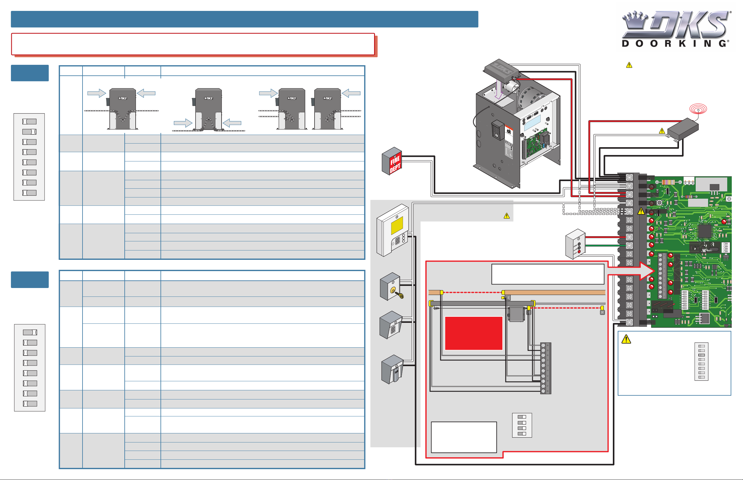
QUICKSTART “BASIC” GUIDELINES FOR MODEL 9150 - DIP-SWITCH AND WIRING REFERENCE
Model 9150 is intended for installation only on sliding gates used for vehicles.
Pedestrians must be supplied with a separate access opening. For safety and installation instructions, please refer to the Installation/Owner’s manual. 120 S. Glasgow Avenue
Inglewood, California 90301
U.S.A.

Other manuals for 9150 Series

2

Other DoorKing Gate Opener manuals

DoorKing 9150 Series Operating instructions

DoorKing

DoorKing 9150 Series Operating instructions

DoorKing 6004 User manual

DoorKing

DoorKing 6004 User manual

DoorKing 6003 User manual

DoorKing

DoorKing 6003 User manual

DoorKing 6555 Operating instructions

DoorKing

DoorKing 6555 Operating instructions

DoorKing Series 9500 User manual

DoorKing

DoorKing Series 9500 User manual

DoorKing 6400 User manual

DoorKing

DoorKing 6400 User manual

DoorKing 6006 User manual

DoorKing

DoorKing 6006 User manual

DoorKing 9100 User manual

DoorKing

DoorKing 9100 User manual

DoorKing Series 9500 Operating instructions

DoorKing

DoorKing Series 9500 Operating instructions

DoorKing 1601 Series User manual

DoorKing

DoorKing 1601 Series User manual

DoorKing 1603 Operating instructions

DoorKing

DoorKing 1603 Operating instructions

DoorKing 1175 Operating instructions

DoorKing

DoorKing 1175 Operating instructions

DoorKing 9245 Operating instructions

DoorKing

DoorKing 9245 Operating instructions

DoorKing 9150 Series Operating instructions

DoorKing

DoorKing 9150 Series Operating instructions

DoorKing 9000-080 Operating instructions

DoorKing

DoorKing 9000-080 Operating instructions

DoorKing 1601-295 User manual

DoorKing

DoorKing 1601-295 User manual

DoorKing 9245 User manual

DoorKing

DoorKing 9245 User manual

DoorKing 6500 Series Operating instructions

DoorKing

DoorKing 6500 Series Operating instructions

DoorKing 1601-235 User manual

DoorKing

DoorKing 1601-235 User manual

DoorKing Series 9500 Installation instructions

DoorKing

DoorKing Series 9500 Installation instructions

DoorKing 9000 Series User manual

DoorKing

DoorKing 9000 Series User manual

DoorKing 1602-162 User manual

DoorKing

DoorKing 1602-162 User manual

DoorKing 6400 User manual

DoorKing

DoorKing 6400 User manual

DoorKing 6400 User manual

DoorKing

DoorKing 6400 User manual

Popular Gate Opener manuals by other brands

CARDIN ELETTRONIC 100/SL1524 instruction manual

CARDIN ELETTRONIC

CARDIN ELETTRONIC 100/SL1524 instruction manual

SEA saturn-boxer 2000 user manual

SEA

SEA saturn-boxer 2000 user manual

A-P-A Eco-Swing 90 installation manual

A-P-A

A-P-A Eco-Swing 90 installation manual

Infineon Technologies IR HiRel RIC74424EVAL1 user guide

Infineon Technologies

Infineon Technologies IR HiRel RIC74424EVAL1 user guide

vds AMICO 400DG Technical installation manual

vds

vds AMICO 400DG Technical installation manual

Delton CARRERA Technical installation manual

Delton

Delton CARRERA Technical installation manual

FAAC 615 instruction manual

FAAC

FAAC 615 instruction manual

Dictator DIREKT 200 installation instructions

Dictator

Dictator DIREKT 200 installation instructions

Daspi BIG FOOT instruction manual

Daspi

Daspi BIG FOOT instruction manual

BFT AKTA A30 installation manual

BFT

BFT AKTA A30 installation manual

BeBPROGET ROUND Manual instruction

BeBPROGET

BeBPROGET ROUND Manual instruction

Daspi JENNY instruction manual

Daspi

Daspi JENNY instruction manual

Genius MISTRAL ENV manual

Genius

Genius MISTRAL ENV manual

CAME ZLX24MA manual

CAME

CAME ZLX24MA manual

Keyautomation TURBO 400 Instructions and warnings for installation and use

Keyautomation

Keyautomation TURBO 400 Instructions and warnings for installation and use

Grant's Automation e-Gate SLD-24V-D instruction manual

Grant's Automation

Grant's Automation e-Gate SLD-24V-D instruction manual

Power Master SG 2004 installation manual

Power Master

Power Master SG 2004 installation manual

Entrematic CUBIC6H Quick reference guide

Entrematic

Entrematic CUBIC6H Quick reference guide

manuals.online logo
manuals.online logoBrands
  • About & Mission
  • Contact us
  • Privacy Policy
  • Terms and Conditions

Copyright 2025 Manuals.Online. All Rights Reserved.