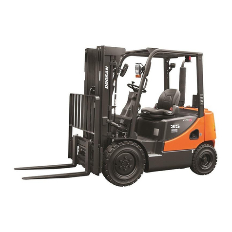
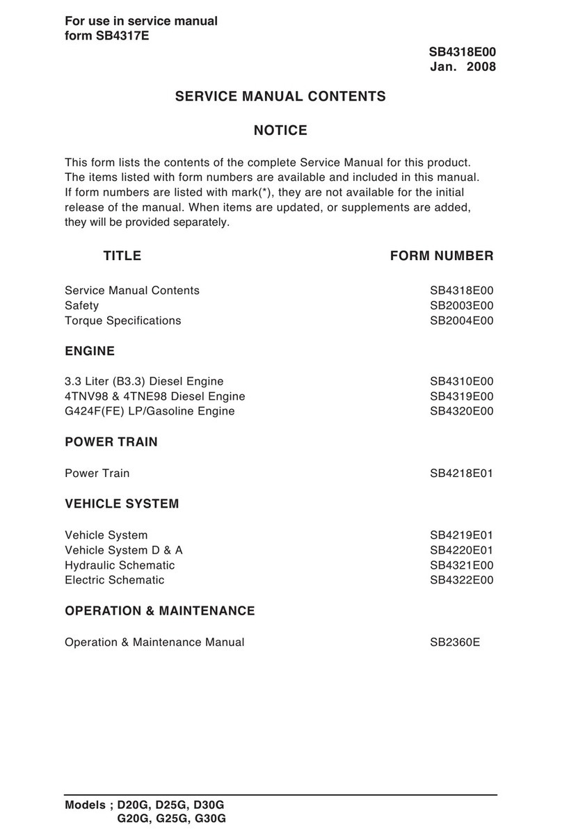
Doosan D15S-5 User manual

Vehicle System
Specification
Systems Operation
Testing & Adjusting
D15S-5, D18S-5, D20SC-5
G15S-5, G18S-5, G20SC-5
GC15S-5, GC18S-5, GC20SC-5
SB4365E01
June. 2011


1
Important Safety Information
Most accidents involving product operation, maintenance and repair are caused by failure to observe basic
safety rules or precautions. An accident can often be avoided by recognizing potentially hazardous situations
before an accident occurs. A person must be alert to potential hazards. This person should also have the
necessary training, skills and tools to perform these functions properly.
Read and understand all safety precautions and warnings before operating or performing lubrication,
maintenance and repair on this product.
Basic safety precautions are listed in the “Safety“ section of the Service or Technical Manual. Additional safety
precautions are listed in the “Safety“ section of the owner/operation/maintenance publication.
Specific safety warnings for all these publications are provided in the description of operations where hazards
exist. WARNING labels have also been put on the product to provide instructions and to identify specific
hazards. If these hazard warnings are not heeded, bodily injury or death could occur to you or other persons.
Warnings in this publication and on the product labels are identified by the following symbol.
WARNING
Improper operation, lubrication, maintenance or repair of this product can be dangerous and could
result in injury or death.
Do not operate or perform any lubrication, maintenance or repair on this product, until you have read
and understood the operation, lubrication, maintenance and repair information.
Operations that may cause product damage are identified by NOTICE labels on the product and in this
publication.
DOOSAN cannot anticipate every possible circumstance that might involve a potential hazard. The warnings
in this publication and on the product are therefore not all inclusive. If a tool, procedure, work method or
operating technique not specifically recommended by DOOSAN is used, you must satisfy yourself that it is
safe for you and others. You should also ensure that the product will not be damaged or made unsafe by the
operation, lubrication, maintenance or repair procedures you choose.
The information, specifications, and illustrations in this publication are on the basis of information available at
the time it was written. The specifications, torques, pressures, measurements, adjustments, illustrations, and
other items can change at any time. These changes can affect the service given to the product. Obtain the
complete and most current information before starting any job. DOOSAN dealers have the most current
information available.


Vehicle Systems Index
3
Index
Specification ............................................5
Control Valve............................................................5
Hydraulic Pump ........................................................6
Sideshift Cylinder......................................................6
Lift Cylinders.............................................................7
Standard................................................................7
Full Free Triple and Full Free Lift Primary ............7
Full Free Lift Secondary........................................8
Full Free Triple Lift Secondary..............................8
Tilt Cylinder...............................................................9
Steering Wheel.......................................................10
Priority Valve...........................................................10
Steering Unit...........................................................11
Forward and Reverse Control Group .....................12
Brake – SHOE........................................................12
Delayed Engine Shutdown System........................13
Operation ............................................................13
Diagram of Delayed Engine Shutdown System..14
Trouble shooting of Delayed Engine Shutdown
System ................................................................15
Diagnostic Fault Codes.......................................15
Delayed Engine Shutdown System Schematic...16
Delayed Engine Shutdown System Schematic...17
OSS (Operator Sensing System) ...........................20
Operation ............................................................20
Symbols of OSS..................................................20
Operator Sensing System Schematic.................21
Trouble shooting of Operator Sensing System...22
Hydraulic System Operation.................24
Hydraulic Schematic ...........................................24
Control Valve..........................................................26
External View......................................................26
Circuit Schematic................................................26
Inlet Section ........................................................27
Lift Section ..........................................................28
Tilt Section ..........................................................30
Auxiliary Section..................................................31
Outlet Section......................................................32
Relief Valve.........................................................33
Hydraulic Steering system......................................34
Hydraulic Schematic ...........................................34
Steering Cylinder.................................................35
Steering Unit ...................................................... 36
Brake System ........................................................ 38
Master Cylinder.................................................. 38
Shoe Type Brakes.............................................. 39
Parking Brake..................................................... 39
Testing and Adjusting ...........................41
Troubleshooting..................................................... 41
Visual Checks .................................................... 41
Performance Tests............................................. 41
Hydraulic System and Mast ............................... 42
Steering System................................................. 47
Brake System..................................................... 48
Lift Cylinders Air Removal.................................. 50
Hydraulic System................................................... 51
Relief Valve Pressure Check ............................. 51
Lift Relief Valve Check and Adjusment.............. 52
Tilt and Auxiliary Relief Valve Check and
Adjusment.......................................................... 53
Steering System .................................................... 53
Steer Wheel Bearing Adjustment -Pneumatic.... 53
Steer Axle Stop Adjustment-Pneumatic............. 54
Steer Wheel Bearing Adjustment-Cushion ........ 54
Steer Axle Stop Adjustment-Cushion................. 55
Steering System Air Removal............................ 55
Steering System Pressure Check...................... 56
Brake System ........................................................ 58
Brake System Air Removal................................ 58
Pedal Adjustment for Brake & Inching............... 58
Parking Brake Test............................................. 60
Parking Brake Adjustment.................................. 60
Vehicle Systems Specifications
5
Specification
Control Valve
CONTROL VALVE
MODEL MAST
RELIEF PRESSURE
Main Relief Pressure-lift Auxiliary Pressure-tilt,attachment
psi kPa psi kPa
D15S,G(C)15S-5 STD/FF/FFT 2,550±35 17,600±250
2,040±50 14,000±350
D18S,G(C)18S-5 STD/FF/FFT 2,880±35 19,860±250
D20SC,G20SC-5 STD/FF/FFT 3,125±35 21,550±250
(1) Torque for nuts that hold control valve sections together.................................24 to 28 N•m (18 to 21 lb•ft)
(2) Torque for nuts that hold control valve sections together.................................24 to 28 N•m (18 to 21 lb•ft)
(3) Torque for main and auxiliary relief valve .........................................................44 to 49 N•m (32 to 36 lb•ft)
(4) Torque for cap screw that hold spool cap...........................................................10 to 15 N•m (7 to 11 lb•ft)

Vehicle Systems Specifications
6
Hydraulic Pump
Rotation is counterclockwise when seen from drive
end.
Type of pump : Gear
For test, use SAE 10W oil at 65°C (150°F)
Pump output....................19.5 cm³/rev (1.19 in³/rev)
Sideshift Cylinder
(1) Torque for head ...............................270±35 N•m
(200±25 lb•ft)
(2) Torque for piston nut ........................260±25 N•m
(190±20 lb•ft)

Vehicle Systems Specifications
7
Lift Cylinders
Standard
(1) Put Pipe Sealant on the last three threads of
bleed screw and tighten to a torque of... 6±1N•m
(53±9 lb•in)
NOTE : All seals to be lubricated with hydraulic oil.
Full Free Triple and Full Free Lift
Primary
(1) Put Pipe Sealant on the last three threads of
bearing.
(2) Put Pipe Sealant of the last three threads of
bleed screw (not shown) and tighten to a torque
of.........................................6±1 N•m (53±9 lb•in)
NOTE : All seals to be lubricated with hydraulic oil.

Vehicle Systems Specifications
8
Full Free Lift Secondary
(1) Put Pipe Sealant on the last three threads of
bearing.
(2) Put Pipe Sealant on the last three threads of
bleed screw and tighten to a torque of................
..........................................6±1 N•m (53±9 lb•in)
NOTE : All seals to be lubricated with hydraulic oil.
Full Free Triple Lift Secondary
(1) Put Pipe Sealant on the last three thread of
bearing.
(2) Put Pipe Sealant on the last three thread of bleed
screw and tighten to a torque of..........................
..........................................6±1 N•m (53±9 lb•in)
NOTE : All seals to be lubricated with hydraulic oil.

Vehicle Systems Specifications
9
Tilt Cylinder
Truck Model Forward Backward Closed Length Stroke Cylinder P/No.
DG15/18S-5 6° 10° 372.5 mm 82 mm D518277
8° 10° 372.5 mm 91.5 mm 400334-00015
GC15/18S-5 6° 10° 392.5 mm 73 mm D518224
6° 10° 392.5 mm 82 mm A252107
(1) Adjust pivot eye to dimension(Y) with cylinder
open (extended)
(2) Torque for bolt.............95±15 N•m (70±10 lb•ft)
(3) With mast at tilt back position shim as required to
permit no gap between eye (1) and spacer.
Torque for head.......270±35 N•m (200±25 lb•ft)
(4) Torque for jam nut....260±25 N•m(190±20 lb•ft)

Vehicle Systems Specifications
10
Steering Wheel
(1) Torque for steering wheel nut ........75 to 88 N•m
(55 to 65 lb•in)
Priority Valve
Flow ....................................................Load sensing
Relief valve (no adjustment) opens at:
................................8,285±350 kPa (1,200±50 psi)

Vehicle Systems Specifications
11
Steering Unit
(1) Pin (1) in the body must be aligned with internal
pump gear (gerotor) (2) and drive (3) as shown.
(4) Tighten bolts in sequence shown.
Tighten to a first torque of.............14.1±2.8 N•m
(125±25 lb•in)
Tighten to a final torque of............28.2±2.8 N•m
(250±25 lb•in)
(5) Torque for plug....................11.3 N•m (100 lb•in)
Plug to be flush (even) with or below mounting
surface.

Vehicle Systems Specifications
12
Forward and Reverse Control
Group
(1) Torque for bolts (four)...................3.4 to 3.9 N•m
(30 to 34.5 lb•in)
(2) Torque for bolts (two)...................2.8 to 3.4 N•m
(25 to 30 lb•in)
Brake – SHOE
(1) Torque for wheel cylinder bolts (1)... 8 to 12 N•m
(6 to 9 lb•in)

Vehicle Systems Specifications
13
Delayed Engine Shutdown System
Operation
The delayed engine shutdown system will shut the
engine down if no proper action is taken by the
operator. This system makes use of the engine
oil pressure switch, transmission oil temperature
switch and water (coolant) temperature sensor to
get
the required truck condition.
If an engine damaging condition arises, such as too
much oil pressure drop, this system will alert the
operator by warning MIL Lamp.
If the operator ignores this warning and does not
shutdown the engine within thirty seconds, this
delayed engine shutdown system will interrupt the
fuel supply to the engine, thereby saving the engine
from the critical damage.
1. Low engine oil pressure
The warning MIL lamp will turn on when the oil
pressure drops to approximately 28KPa
(4 psi) and the delayed engine shutdown
System will interrupt the fuel supply to the engine
after thirty seconds.
2. Hot engine coolant
The warning MIL lamp will turn on when the
coolant temperature reaches approximately
115℃(239℉) and the delayed engine
shutdown system will interrupt the fuel supply to the
engine after thirty seconds.
3. Hot transmission oil
The warning MIL lamp will turn on
when the transmission oil temperature
reaches approximately 125℃(257℉) and the
delayed engine shutdown system will
interrupt the fuel supply to the engine after thirty
seconds.

Vehicle Systems Specifications
14
Diagram of Delayed Engine Shutdown System
G424I(E) / G424F(E) ENGINE – LP TRUCK
G424I(E) / G424F(E) ENGINE – GAS & DF TRUCK

Vehicle Systems Specifications
15
Trouble shooting of Delayed Engine Shutdown System
When the ignition key is turned on, the MIL Lamp will illuminate and remain on until the engine is started.
Once the engine is started, the MIL Lamp will go out unless one or more fault conditions are present. If a
detected fault condition exists, the fault or faults will be stored in the memory of the small engine control
module (SECM).
Once an active fault occurs, the MIL Lamp will illuminate and remain ON. This signals the operator that a fault
has been detected by the SECM. If the MIL Lamp turns on while operating the lift truck, park the lift truck
and stop the engine, and then check the follows.
Delayed Engine shutdown : Some faults, such as low oil pressure, will cause the MIL Lamp to
illuminate for 30 seconds and then shut down the engine
FAULT DESCRIPTION CODE
(M104 CODE)
ECT Over Range
High
Engine Coolant Temperature Sensor Input is High.
Normally set if coolant sensor wire has been disconnected or
circuit has opened to the SECM 151(15)
ECT Over
Temperature
Fault
Engine Coolant Temperature is High.
The sensor has measured an excessive coolant temperature
typically due to the engine overheating 161(15)
Low Oil Pressure
Fault Low engine oil pressure 521(52)
Transmission Oil
Temperature Excessive transmission oil temperature 933
Diagnostic Fault Codes
DFC PROBABLE FAULT FAULT ACTION CORRECTIVE ACTION FIRST CHECK
151
(15) ECT Range High
Coolant sensor
disconnected
or open circuit
(1) Turn on MIL
(2) Delayed Engine
Shutdown
(3) Check Engine Light
Check if ECT sensor connector is
disconnected or for an open ECT
circuit SECM (Signal) Pin B15 to ECT
Pin 3 SECM (Sensor GND) Pin B1 to
ECT Pin 1
161
(15) ECT Over Temperature
Fault
Engine coolant temperature
is high.
The sensor has measured
an excessive coolant
temperature typically due to
the engine overheating.
(1) Turn on MIL
(2) Delayed Engine
Shutdown
(3) Check Engine Light
Check coolant system for radiator
blockage, proper coolant level and for
leaks in the system.
Possible ECT short to GND, check ECT
signal wiring SECM (Signal) Pin B15 to
ECT pin 3 SECM (Sensor GND) pin B1
to ECT pin 1 SECM (System GND) pin
A16, B 17 Check regulator for coolant
leaks
521
(52) Low Oil Pressure Fault
Low engine oil pressure (1) Turn on MIL
(2) Delayed Engine
Shutdown
(3) Check Engine Light
Check engine oil level
Check electrical connection to the oil
pressure switch SECM Pin B9 to Oil
Pressure Switch
933 Trans Oil Temperature
Excessive Transmission oil
temperature
(1) Turn on MIL
(2) Delayed Engine
Shutdown
Refer to drive train manufacturer’s
Transmission service procedures

Vehicle Systems Specifications
16
Delayed Engine Shutdown System Schematic
DELAYED ENGINE SHUTDOWN : G424I(E) - LP

Vehicle Systems Specifications
17
Delayed Engine Shutdown System Schematic
DELAYED ENGINE SHUTDOWN : G424I(E) - GAS&DF
E/G OIL PR
E/G CHECK
ENG GND
NEAR COILS

Vehicle Systems Specifications
18
Delayed Engine Shutdown System Schematic
DELAYED ENGINE SHUTDOWN : G424F(E) - LP
This manual suits for next models
1
Table of contents
Other Doosan Forklift manuals

Doosan
Doosan D20G Quick start guide

Doosan
Doosan D110S-5 with OCDB User manual

Doosan
Doosan DL200 User manual

Doosan
Doosan DL220 User manual

Doosan
Doosan D35S-9 Manual

Doosan
Doosan D20G User manual

Doosan
Doosan BSL14S-7 User manual

Doosan
Doosan D20S-9 Manual

Doosan
Doosan D50S-5 Manual

Doosan
Doosan D35C-5 FDA04 Manual