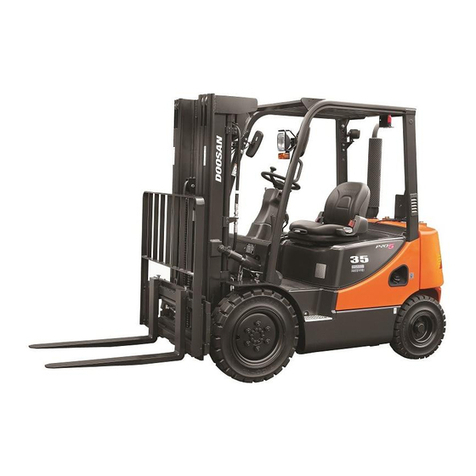
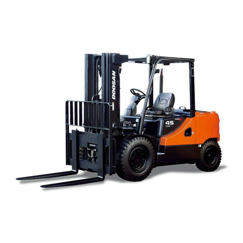
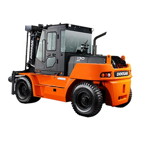
Doosan D20G Quick start guide

Vehicle System
Disassembly & Assembly
D20G, D25G, D30G with B3.3 Engine
D20G, D25G, D30G with 4TNE98 Engine
G20G, G25G, G30G with G424F Engine
G20G, G25G, G30G with G424FE Engine
SB4220E01
Jan.2008


1
WARNING
Important Safety Information
Most accidents involving product operation, maintenance and repair are caused by failure to observe basic
safety rules or precautions. An accident can often be avoided by recognizing potentially hazardous situations
before an accident occurs. A person must be alert to potential hazards. This person should also have the
necessary training, skills and tools to perform these functions properly.
Read and understand all safety precautions and warnings before operating or performing lubrication,
maintenance and repair on this product.
Basic safety precautions are listed in the “Safety” section of the Service or Technical Manual. Additional safety
precautions are listed in the “Safety” section of the owner/operation/maintenance publication. Specific safety
warnings for all these publications are provided in the description of operations where hazards exist.
WARNING labels have also been put on the product to provide instructions and to identify specific hazards. If
these hazard warnings are not heeded, bodily injury or death could occur to you or other persons. Warnings in
this publication and on the product labels are identified by the following symbol.
Improper operation, lubrication, maintenance or repair of this product can be dangerous and could
result in injury or death. Do not operate or perform any lubrication, maintenance or repair on this
product, until you have read and understood the operation, lubrication, maintenance and repair
information.
Operations that may cause product damage are identified by NOTICE labels on the product and in this
publication.
DOOSAN cannot anticipate every possible circumstance that might involve a potential hazard. The warnings
in this publication and on the product are therefore not all inclusive. If a tool, procedure, work method or
operating technique not specifically recommended by DOOSAN is used, you must satisfy yourself that it is
safe for you and others. You should also ensure that the product will not be damaged or made unsafe by the
operation, lubrication, maintenance or repair procedures you choose.
The information, specifications, and illustrations in this publication are on the basis of information available at
the time it was written. The specifications, torques, pressures, measurements, adjustments, illustrations, and
other items can change at any time. These changes can affect the service given to the product. Obtain the
complete and most current information before starting any job. DOOSAN dealers have the most current
information available.
Vehicle System Index3
Index
Hood (with seat) Assembly................................... 5
Overhead Guard .................................................. 6
Forks.................................................................... 7
Backrest............................................................... 7
Carriage............................................................... 7
Mast....................................................................13
Standard Lift Cylinder..........................................28
Secondary Lift Cylinder .......................................31
Primary Lift Cylinder............................................34
Tilt Cylinder.........................................................37
Hydraulic Pump...................................................42
Steering Wheel....................................................51
Steering Unit.......................................................52
Brake Master Cylinder.........................................62
Steer Wheel & Bearing........................................64
Steering Knuckle, Kingpin, And Bearing ..............66
Steer Axle...........................................................67
Steering Cylinder.................................................69
Hydraulic Control Valve.......................................73
Counterweight.....................................................80
Engine ................................................................81
WARNING
Disconnect batteries before performance of any
service work.


Vehicle System Disassembly & Assembly5
Hood (with seat) Assembly
Remove & Install Hood (with seat)
Assembly
WARNING
The hood and seat assembly can fall when nut
(1)is removed from the support cylinder rod. To
avoid personal injury, support the seat and hood
assembly before removing nut (1).
1. Raise the hood. Support the hood with a hoist.
2. Remove nut (1) from the support cylinder.
Remove the cylinder rod from the bracket.
3. Lower the hood.
4. Remove the bolts (2) from the cover. Remove
cover.
5. Remove the washers and four bolts (3).
6. Release latch. Use the hoist to remove hood and
seat assembly (4). The hood and seat assembly
weighs approximately 52 kg (115 lb)
7. Install the hood and seat assembly in the reverse
order of removal.

Vehicle System Disassembly & Assembly6
Overhead Guard
Remove & Install Overhead Guard
1. Support overhead guard (1) with lifting straps and
a hoist
.
2. Remove the washers, nuts, and bolts (2).
3. Remove the washers, nuts, and two bolts (3).
4. Remove front overhead guard (1). Front over
head guard (1) weighs approximately 30 kg (66 lb).
5. Remove the washers, nuts, and four bolts (4).
6. Remove rear Leg (5).
7. Install front overhead guard (1) and rear leg (5) in
the reverse order of removal.

Vehicle System Disassembly & Assembly7
Forks
Remove & Install Forks
1. Remove stopper bolt and washer (3).
2. Lift fork pin (1).
3. Use a suitable C-clamp, strap and hoist to support
the fork as shown.
4. Slide the fork to slot (2) in the middle of the
carriage
5. Remove the fork. The weight of the fork is
approximately 50 kg (110 lb).
6. Repeat steps 1 through 4 for the remaining fork.
7. Install the forks in the reverse order of removal.
8. Put the forks in position. Lower both fork pins (1)
to lock the forks in position.
9. Install stopper bolt and washer (3). Be careful not
to miss this step.
Backrest
Remove & Install Backrest
1. Fasten a hoist to the backrest. Remove bolts (2)
that fasten the backrest to the carriage.
2. Remove backrest (1). Backrest (1) weighs about
40 kg (90 lb).
3. install backrest (1) in the reverse order of removal.
Carriage
Remove & Install Carriage
Start By:
a. Remove stopper bolt and washer (3).
b. Lift fork pin (1).
Tools Needed A
Retaining Ring Pliers 1

Vehicle System Disassembly & Assembly8
(Typical Example)
(Typical Example)
1. Raise carriage (1). Position a wooden block as
shown. Lower carriage (1) onto the wooden block.
2. Disconnect two hydraulic lines (4) from side
shifter cylinder (2). Plug and cap all openings to
prevent contamination and debris from entering
system.
WARNING
To prevent personal injury be sure pressure in
the hydraulic system has been released before
disconnecting any hydraulic lines. Slowly loosen
the cap of the hydraulic tank to release any
pressure in the tank. Be cautious of hot
hydraulic coil when any lines are disconnected
in the hydraulic system.
NOTE: For purposes of reassembly, identify and
mark all hydraulic lines and connectors
before removing or disconnecting.
(Typical Example)
3. Remove four bolts (8) from the chain guard/hose
support assembly (6). Set the hoses aside, clear
of the primary cylinder and cross head.
(Typical Example)
4. Remove two bolts (10) from the hose mounting
bracket. Set the hoses aside. Remove two nuts
(9) from the chain anchors. Set the chains aside,
clear of the mast.

Vehicle System Disassembly & Assembly9
(Typical Example)
5. Use tool (A) to remove retainer ring(11) from the
cross head shaft.
6. Remove cross head (12) from the shaft.
(Typical Example)
7. Raise the inner mast to pull out carriage as shown.
8. Remove carriage (14) from bottom of inner mast
(15). Carriage (14) weighs 116kg (255 lb).
NOTE: Use the following steps to install the carriage.
9. Raise the inner mast to put in the carriage onto
the mast, and lower the inner mast to cover
carriage (1) bearing fully.

Vehicle System Disassembly & Assembly10
(Typical Example)
10. Install cross head (12) and retaining ring(11).
(Typical Example)
11. Put the chains in position over cross head
(12).Install nuts(9) onto the chain anchors to a
torque of 270 ± 40 N•m (200 ± 30 lb•ft).
Install bolts (10) onto the hose mounting bracket.
(Typical Example)
12. Install chain guard/hose support assembly (6)
and four bolts(8) to a torque of 8 ± 2 N•m (6 ±
1.5lb•ft)
(Typical Example)
13. Connect two hydraulic line (4) in their original
positions.
End By:
a. Install backrest.
b. Install forks.
Disassemble Carriage
Start By:
a. Remove carriage.
(Typical Example)
1. Remove the roll pins and pins (2) to disconnect
chains (1).

Vehicle System Disassembly & Assembly11
(Typical Example)
2. Remove four lower roller bearings (3) and the
shims from the carriage.
(Typical Example)
2. Remove screw (5) and washer (4). Remove top
roller bearings (6) and the shims.
Assemble Carriage
NOTE: The standard, Full Free Lift and Full Free
Triple Lift carriage load bearings are all
adjusted the same way. The Full Free Triple
Lift carriage is shown in the following
illustrations.
To make the carriage clearance adjustments,
carriage must be removed from the mast.
Use the procedure that follows to adjust carriage
load bearings.
Carriage adjustment (3) Upper bearings. (4) Shims.
(5) Bolt. (6) Screw. (7)Middle bearings. (8) Lower
bearings. (A) Zero clearance. (B) 6.0 to 9.0 mm.
(.236 to .354 in) clearance. (C) Minimum clearance.
1. Select lower bearings from the chart to obtain
minimum clearance (B) between bearings and
channel leg for full channel length. Use same
bearing in all six locations.
Mast And Carriage Bearings
Part No. Bearing Size Bearing O.D.*
D581814 Under Size 108.6 mm (4.276 in)
D581815 Standard 109.6 mm (4.135 in)
D581816 Over Size 110.7 mm (4.358 in)
* Permissible tolerance ±0.08 mm (.003in)

Vehicle System Disassembly & Assembly12
2. Find narrowest point by ruler on the inner mast in
the area where the bearings make contact.
3. Install enough shims (4) that have been divided
into two equal groups behind bearings (3). At
installation, there is to be contact [zero clearance
(A)] between the bearings and the narrowest point
of inner mast.
4. Do step 2 through 3 for other sets of bearings
(8),(9).
(Typical Example)
(Typical Example)
5. Tighten screw (5) that holds the top bearings to
the carriage to a torque of 34±7 N•m (25±5 lb•ft).
(Typical Example)
6. Position chains (6) on the carriage. Install pins (7)
and the roll pins.
End By:
a. Install carriage, raise the inner mast and insert the
carriage from the bottom of inner mast.

Vehicle System Disassembly & Assembly13
Mast
Remove & Install Mast
Start By:
a. Remove forks.
b. Place truck on the pit so to disassemble and
assemble the mast mounting caps.
(Typical Example)
1. Support mast assembly (2) with a hoist and two
straps (1) as shown.
NOTICE
Place identification marks on all hydraulic
connectors and hoses to assure proper installation.
Plug and cap all hydraulic connectors and hoses to
avoid debris and contamination from entering the
system.
2. Disconnect hose (3).
3. Disconnect the hydraulic return lines (not shown).
WARNING
Tilt cylinders (7) can drop when pin (6) is
removed. To avoid component damage or
personal injury, support tilt cylinder (7) while
removing pin (6).
4. Remove bolt (5) from each side of mast assembly
(2).
5. Remove pin (6) from the tilt cylinders on each
side of the mast assembly (2).
6. Tilt backward mast assembly (2) fully with the
hoist.
Remove bolts (8) and cap (9) from each side of
the base of mast assembly (2) in the pit.

Vehicle System Disassembly & Assembly14
WARNING
Loosen the tension of straps to be connected
with hoist when mast assembly (2) is tilted
forward. If straps are too tight, mast assembly
(2) could slide off when bolts(8) are removed.
7. Use the hoist to remove mast assembly (2) from
the machine.
8. Install the mast in the reverse order of removal.
End By:
a. Install forks.
b. Fill hydraulic oil to tank*.
* Refer to the Operation and Maintenance Manual
for further information.
Disassemble Mast
Start By:
a. Remove primary lift cylinder.
b. Remove mast.
NOTE: The following disassembly and assembly
procedure is for a full free triple lift mast.
(Typical Example)
1. Remove hoses (1) along with the hose support
clamps.

Vehicle System Disassembly & Assembly15
2. Remove hose sheave (3).
3. Remove chain nut (4) from the top of the
mast(each side).
(Typical Example)
4. Disconnect and remove chains (5) from the
bottom of the mast.
(STD Mast)
(FFT Mast)
5. Remove top cylinder retainer bolt (6) from each
side of the mast.
6. Disconnect lift hose (7) and return hose (8).

Vehicle System Disassembly & Assembly16
(STD Mast)
7. Remove cylinder bottom retainer bolt (9) from
each side of mast. (STD mast only)
(STD Mast)
(FFT Mast)
8. Remove cylinder retainer brackets (10) from each
cylinder.
(STD Mast)
(FFT Mast)
9. Fasten a nylon strap and hoist to lift cylinder, as
shown. Hoist and remove lift cylinder (11). Each
cylinder weighs about 50 kg (110 lb).

Vehicle System Disassembly & Assembly17
10. Check the condition of bearings (12) located in
each of the tilt cylinder pin bores. Replace
bearings (12) with new if worn or damaged.
11. Check the condition of the bearings (13) located
in each of the mast mounting bores. Replace
the bearings (13) with new if worn or damaged.
(Typical Example)
12. Fasten nylon straps and hoist to inner channel
(14). Remove inner channel (14). The weight of
the inner channel is approximately 150kg (330
lb).
(Typical Example)
13. Remove rollers (15) and the shims from the
inner channel mast.
(Typical Example)
14. Fasten nylon straps and a hoist to the
intermediate mast channel (16). Remove mast
channel (16).The intermediate mast channel
weighs approximately 168kg (370 lb). (FFT
mast only)

Vehicle System Disassembly & Assembly18
(Typical Example)
15. Remove rollers (17) and the shims from the
intermediate mast channel. (FFT mast only)
16. Remove nylon pads (18) and the shims.
(Typical Example)
17. Remove rollers (19) and the shims from the
stationary mast channel.
18. Remove nylon pads (20) and the shims.
Other manuals for D20G
2
This manual suits for next models
5
Table of contents
Other Doosan Forklift manuals