Doran Scales 4300 User manual

4300 Series
Digital Weight Indicator
Technical Manual
MAN334 – Rev 1 Doran Scales, Inc. www.doranscales.com

Table of Contents
Introduction .......................................................................................................................... 1
Unpacking Your Scale .....................................................................................................................1
4300 Indicator Specifications ..........................................................................................................2
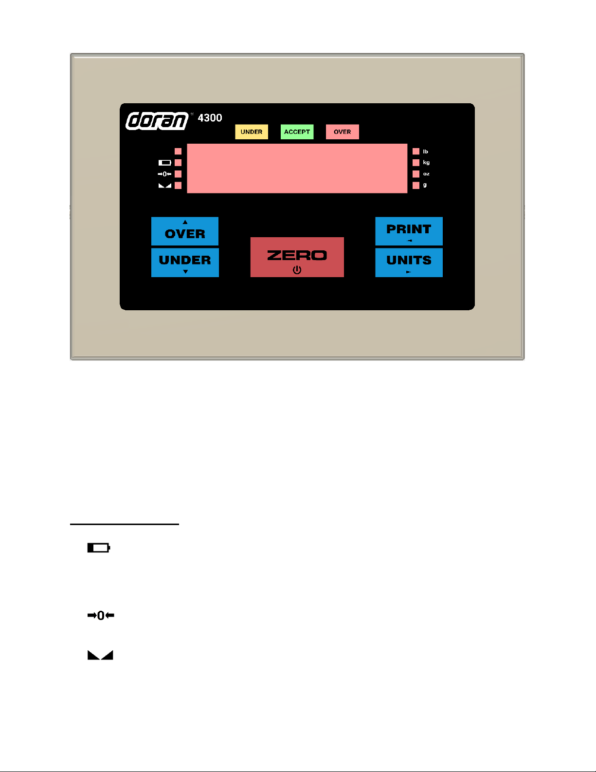
Scale Annunciators.........................................................................................................................3
Power Up.......................................................................................................................................4
Basic eighing Operation ..............................................................................................................4
ZERO .............................................................................................................................................4
UNITS ............................................................................................................................................4
PRINT ............................................................................................................................................4
OVER .............................................................................................................................................5
UNDER ...........................................................................................................................................5
Battery Operation ................................................................................................................. 6
Power Off ......................................................................................................................................6
Low Battery Indication ..................................................................................................................6
Recharging Battery.........................................................................................................................6
Three Band Checkweighing .................................................................................................... 7
Three Band Checkweighing ............................................................................................................7
Digital Entry of Checkweigh Limits ..................................................................................................7
eight Reference and Digital Entry of Checkweigh Limits ...............................................................7
eight Reference Entry of Checkweigh Limits ................................................................................7
Five Band Checkweighing ...................................................................................................... 8
Five Band Checkweighing ...............................................................................................................8
Digital Entry of High and Low Limits................................................................................................8
eight Reference and Digital Entry of High and Low Limits .............................................................8
eight Reference Entry of High and Low Limits ..............................................................................9
Zero Band Checkweighing .................................................................................................... 10
Zero Band Checkweighing ............................................................................................................ 10
Installation Guide ................................................................................................................ 11
Removing and Replacing the Rear Panel ....................................................................................... 11
Load Cell Connection .................................................................................................................... 12
Power Connection and Fuse ......................................................................................................... 13
RS232 and Remote Switch Connection .......................................................................................... 13
Calibration Guide ................................................................................................................ 15
Entering Calibration and Parameter Setup Mode .......................................................................... 15
Exit Calibration and Parameter Setup Mode ................................................................................. 15
Set Scale Capacity ........................................................................................................................ 15
Set Scale Count By ....................................................................................................................... 16
Calibration ................................................................................................................................... 16
Scale Calibration Error Troubleshooting ........................................................................................ 17
Scale Parameter Setup ......................................................................................................... 18
Entering Calibration and Parameter Setup Mode .......................................................................... 18
Exit Calibration and Parameter Setup Mode ................................................................................. 18
Navigating Parameter Menu ........................................................................................................ 18
Parameter Groups ........................................................................................................................ 19

Legal for Trade Restrictions .......................................................................................................... 19
Audit Counters ............................................................................................................................. 19
Software Part Number and Revision Level .................................................................................... 19
Capacity and Calibration - 1 CAL
1 CAL1 CAL
1 CAL .................................................................................................. 20
General Settings - 2 Cng
2 Cng2 Cng
2 Cng ............................................................................................................ 22
Serial Port 1 - 3 SEr1
3 SEr13 SEr1
3 SEr1 .................................................................................................................. 25
Serial Port 2 - 4 SEr2
4 SEr24 SEr2
4 SEr2 .................................................................................................................. 26
Ethernet - 5 Eth
5 Eth5 Eth
5 Eth ......................................................................................................................... 27
ireless Ethernet - 6 uui
6 uui6 uui
6 uui .......................................................................................................... 28
Bluetooth - 7 bt
7 bt7 bt
7 bt ......................................................................................................................... 29
USB - 8 USb
8 USb8 USb
8 USb ................................................................................................................................ 30
Checkweighing - 9 chuu
9 chuu9 chuu
9 chuu .............................................................................................................. 31
Exit - 99 don
99 don99 don
99 don ............................................................................................................................... 33
Data Communications ......................................................................................................... 34
Data Communication Modes ........................................................................................................ 34
Data String Formatting ................................................................................................................. 34
Custom Data String Configuration ................................................................................................ 39
4-20mA Analog Output Option ............................................................................................ 41
ired Ethernet Option ........................................................................................................ 42
ireless 802.11b/g Ethernet Option .................................................................................... 43
Bluetooth Option ................................................................................................................ 46
Bluetooth Pairing Instructions ...................................................................................................... 47
Troubleshooting .................................................................................................................. 52
Scale Messages ............................................................................................................................ 52
Error Messages ............................................................................................................................ 53
Default to Factory Settings ........................................................................................................... 54

1
Introduction
Thank you for purchasing a Doran Scales product. Please read this manual to ensure
obtaining all the benefits that the 4300 can provide. If any questions arise, please
contact the Doran Scales Technical Support Department at 1-800-262-6844.
Unpacking Your Scale
Before unpacking your Doran scale, please read the instructions in this section. Your
new scale is a durable industrial product, but it is also a sensitive weighing instrument.
Normal care should be taken when handling and using this product. Improper handling
or abuse can damage the scale and result in costly repairs that will not be covered by
the warranty. If you notice any shipping damage, notify the shipper immediately. Please
observe the following precautions to insure years of trouble free service from your new
scale.
•DO NOT drop the scale.
•DO NOT immerse the scale.
•DO NOT drop objects on the platform.
•DO NOT pick up the scale by the top of the weighing platform.
•Carefully remove the scale from the shipping carton.

2
4300 Indicator Specifications
NTEP Certificate Class III – 10,000d; Cert. #97-038A1
CWM Certificate Class III – 10,000d; Cert. #AM-5201
Enclosure 304 Stainless Steel
Product Dimensions 10” W x 6.75” H x 3.5” D
Environmental Protection
IP69K
Legal for Trade
Temperature Range 14 F to 104F (-10 C to +40 C)
Resolution Range 200d to 50,000d
Analog Signal Sensitivity 0.16 µV/e minimum, 0.5 µV/e typical
System Linearity 0.01% full scale
Analog Signal Range -0.5mV/V to 5 mV/V with 4 and 6 wire input
Excitation Voltage 5 VDC
Number of Load Cells Up to 8 350 Ohm
Scale Inputs One
Calibration Range Calibrate between 100% and 2% of capacity
Power Input 100 – 240VAC 50/60Hz
Battery Option Internal Rechargeable Sealed Lead Acid Battery
6VDC, 60 hours of continuous use, 1000 recharge cycles
Display 0.8" high, 6 digit LED
Displayed Units lb, kg, oz, g, lb:oz
Capacity Range 1 to 999,000 lb
Serial Interface Two Bi-directional RS-232 ports standard
Optional Communication
Options
Ethernet
Wi-Fi – 802.11b/g
Bluetooth – 4.0, Class 3, SPP Protocol
USB – 2.0, CDC Protocol
4-20 mA – Active current loop
Audible Alarms
Light Tower
Controls ZERO, UNITS, PRINT, OVER and UNDER
Digital IO Two remote switch inputs

3
Fig. 1: Model 4300 Front Panel Layout
The operational controls for the Model 4300 consist of the ZERO, PRINT, UNITS, OVER
and UNDER buttons. A six digit LED display is used to display weight and operator
messages during scale operation. Three lights, above the LED display indicate
checkweighing status. Scale status is displayed on annunciators located to the left of
the display area. Weight units are displayed on four annunciators located to the right of
the display.
Scale Annunciators
Battery option status indicator. When the annunciator illuminates, the
battery charge is low and the scale should be plugged in to recharge the
battery. While the scale is charging, the battery annunciator will flash.
When the charging is complete, the annunciator will turn off.
Center of zero. The annunciator will illuminate while the scale is
displaying a zero weight.
Motion indicator. This symbol represents motion or instability of the
weight. The annunciator will illuminate when motion is sensed on the
platform. Changes in weight, vibration or air currents can cause the scale
to go into motion.

4
Under illuminates to indicate weight is below the Under target and above
the Low target or flashes if below the Low target.
Accept illuminates to indicate weight is at or above the Under target and at
or below the Over target.
Over illuminates to indicate weight is above the Over target and below the
High target or flashes if above the High target.
Power Up
Connect the cord to a compatible power source.
For indicators with battery option, press and hold ZERO.
Basic Weighing Operation
1) Remove all items from the scale platform
2) Press the ZERO button to zero the scale
3) The weight display now reads zero
4) Place an item on the scale platform and wait for the motion annunciator to turn
off, indicating an accurate, stable weight
ZERO
ZERO is used to zero the scale. To zero the scale, wait until the scale is stable and
press the ZERO button. The scale will not zero if the scale is in motion. The zero
function will operate over the entire capacity of the scale.
The scale is equipped with a Zero on Demand parameter which zeros the scale upon
the next stable reading after ZERO is pressed.
UNITS
UNITS selects the current unit of measure. Press UNITS to change the current unit.
The units annunciator to the right of the display will indicate the current unit or measure:
lb, oz, kg, g or lb:oz.
Each unit can be enabled or disabled in the scale parameter setup. Lb:oz is disabled by
default. Lb:oz not available for tolerance values.
PRINT
PRINT transmits data to a printer or other external devices. When the data is
transmitted, the left most display digit will momentarily display an "r" to confirm data
transmission.
There are many parameters that customize the control of manual and automatic
transmission of data. Data can be transmitted via standard RS232, Ethernet, WiFi,
Bluetooth or USB. Contact Doran Tech Support at 800-262-6844 for support.

5
OVER
OVER allows entry of the upper checkweighing limits. It is also used to increment a
checkweighing value that is being modified.
UNDER
UNDER allows entry of the lower checkweighing limits. It is also used to decrement a
checkweighing value that is being modified.

6
Battery Operation
The 4300 can be optionally configured with a self-contained Rechargeable Sealed
Lead-Acid battery and charging circuit, both internal. The scale is designed to run
continuously for up to 60 hours with a single 350 ohm load cell. To maximize battery
life, leave the auto-off timer enabled which will automatically power down the scale after
a period of non-use.
Power Off
1) Manual - Press and hold the ZERO push button until the display turns off. The scale
will not turn off if plugged in but will instead display “r b”.
2) Automatic - At the end of the Unit On Timer (td ) scale parameter setting. The scale
will not turn off if plugged in.
Low Battery Indication
The battery annunciator indicates that the battery is in need of recharging. Once it turns
on, there will be approximately one hour of battery life remaining before the scale turns
off. Multiple load cells, USB, Bluetooth, Ethernet, 4-20mA and WiFi communications will
reduce battery life.
Recharging Battery
To charge the battery, plug the line cord into a wall outlet. While the scale is charging,
the battery annunciator will flash. The charging circuit will fully charge the battery in
approximately eight hours. When the charging is complete, the annunciator will turn off.
The scale can be used while recharging the battery.
Leaving the scale plugged in will ensure a fully charged battery and will not affect the life
of the battery. The battery is able to support up to 1000 recharges. This is an estimate
as many factors can affect battery life, including severe temperature changes and
charging before the scale displays low battery.

7
Three Band Checkweighing
Three band checkweighing classifies weighments into over, accept and under. The
4300 defaults to three band checkweighing. Note that lb:oz is not supported for
checkweighing limits.
Three Band Checkweighing
1. Remove all items from the scale platform
2. Press ZERO and the display will read zero weight
3. Place an item on the scale platform and wait for the scale to stabilize
4. Accept, Over or Under annunciators indicate checkweigh status
Digital Entry of Checkweigh Limits
1. Press OVER or UNDER
2. The display will briefly read over or under followed by the current limit
3. Press either OVER to increase the weight value or press UNDER to decrease the
weight value. Pressing and holding will accelerate the weight scroll.
4. Press ZERO to save the value or press PRINT to exit without saving
5. !"Vd is displayed if saved or "bort is shown if aborted
Weight Reference and Digital Entry of Checkweigh Limits
1. Press ZERO
2. Place a target item on the scale
3. Press OVER or UNDER
4. The display will briefly read ovr or undr followed by the weight on the platform
5. Press either OVER to increase the weight value or press UNDER to decrease the
weight value. Pressing and holding will accelerate the weight scroll.
6. Press ZERO to save the value or press PRINT to exit without saving
7. !"Vd is displayed if saved or "bort is shown if aborted
NOTE: To digitally adjust the platform weight for OVER and UNDER limits, the
parameter C.E. must be set to SCS.
Weight Reference Entry of Checkweigh Limits
1. Press ZERO
2. Place a weight equal to the desired OVER or UNDER limit on the platform
3. Press OVER or UNDER
4. ovr or undr is displayed and then !"Vd to indicate the new OVER limit was
saved.
NOTE: To enable Push-button entry of OVER and UNDER limits, the C.E. parameter
must be set to b.

8
Five Band Checkweighing
Five band checkweighing classifies weighments into high, over, accept, under and low.
See three band checkweighing to set over and under checkweigh limits. The C.o.
parameter must be set for five band checkweighing to enable this capability. Note that
lb:oz is not supported for checkweighing limits.
Five Band Checkweighing
1. Press ZERO
2. Place an item on the scale
3. Checkweigh status is indicated as follows
a. Flashing OVER = HIGH
b. Solid OVER = OVER
c. Solid ACCEPT = ACCEPT
d. Solid UNDER = UNDER
e. Flashing UNDER = LOW
Digital Entry of High and Low Limits
1. Press and hold the OVER or UNDER until the display reads High or ouu
respectively
2. The current weight value of the saved limit is displayed and checkweigh status
annunciators will flash
3. Press either OVER to increase the weight value or press UNDER to decrease the
weight value. Pressing and holding will accelerate the weight scroll.
4. Press ZERO to save the value or press PRINT to exit without saving
5. !"Vd is displayed if saved or "bort is shown if aborted
Weight Reference and Digital Entry of High and Low Limits
1. Press ZERO
2. Place an item of the desired weight on the scale platform
3. Press and hold the OVER or UNDER until the display reads High or ouu
respectively
4. The current weight value of the saved limit is displayed and checkweigh status
annunciators will flash
5. Press either OVER to increase the weight value or press UNDER to decrease the
weight value. Pressing and holding will accelerate the weight scroll.
6. Press ZERO to save the value or press PRINT to exit without saving
7. !"Vd is displayed if saved or "bort is shown if aborted

9
Weight Reference Entry of High and Low Limits
1. Press ZERO
2. Place an item of the desired weight on the scale platform
3. Press and hold the OVER or UNDER until the display reads High or ouu
respectively
4. The display will briefly read ovr or undr followed by the weight on the platform
and checkweigh status annunciators will flash
5. Press either OVER to increase the weight value or press UNDER to decrease the
weight value. Pressing and holding will accelerate the weight scroll.
6. Press ZERO to save the value or press PRINT to exit without saving
7. !"Vd is displayed if saved or "bort is shown if aborted

10
Zero Band Checkweighing
Basic checkweighing - simply set the desired weight on the platform, press zero and
checkweigh based upon the standard tolerances in the O.U. parameter.
Zero Band Checkweighing
1. Remove all items from the scale platform
2. Place the target weight on the scale platform
3. Press ZERO and the display will read zero weight
4. Remove the target weight
5. Place an item on the scale platform and wait for the scale to stabilize
6. A zero weight will indicate the item is exactly the target weight. Any weight above
or below zero indicates the amount of weight away from the target weight.
7. Accept, Over or Under will be displayed

11
Installation Guide
Fig. 2: Motherboard Layout
Removing and Replacing the Rear Panel
Before you remove the rear panel, remove AC power. Power down the scale if the
optional battery power is present. Removing the rear panel requires a 5/16” nut driver.
To replace the rear panel and achieve a tight seal, each screw requires a rubber
bonded washer and the gasket needs to be in place. Tighten screws to 20 in-lb to
achieve proper sealing. Tighten all watertight glands until the cable exiting the watertight
can no longer slide through the watertight – this is usually finger tight plus a quarter turn
with a wrench for a seal.

12
Load Cell Connection
Load cell connections are made through terminal block TB1. The power cord connects
to terminal block TB5 adjacent to the transformer.
Fig. 3: Load Cell and Power (lower left of board)
4 wire load cell
6 wire load cell
J1
Jumper
In Out
J2
Jumper
In Out
Load Cell Input
(
TB1
)
Description
Load Cell Color Code
+ SIG + Signal Red
- SIG - Signal White
+ EX + Excitation Green
- EX - Excitation Black
+ SEN + Sense Signal Blue
- SEN - Sense Signal Brown

13
Power Connection and Fuse
Power input is located at terminal block TB5, next to the fuse and black transformer.
Neutral
Ground
Line (Hot)
N G L
Make sure power is off before replacing the fuse. The scale's fuse (F1) is located next
to the power terminal (J1).
The scale has a filtered power supply to reduce the effects of normal line noise, but it
cannot limit severe fluctuations. Be sure the AC power is not excessively noisy. If
problems occur, noise producing devices may have to be suppressed to minimize their
effect.
RS232 and Remote Switch Connection
The Remote Switch and Serial Communications are located in the TB3 terminal block.
Option cables are passed through watertight glands mounted on the rear cover of the
indicator.
Fig. 4: Serial and Remote Switch Connection (upper right of board)

14
TB3 RS232 and Remote Switch Connections
Description
Wire Color Code
RX1 RS232 Port 1 Receive White
TX1 RS232 Port 1 Transmit Red
GND Common Ground Black
SW1 Remote Switch 1 Input White
SW2 Remote Switch 2 Input White
RX2 RS232 Port 2 Receive White
TX2 RS232 Port 2 Transmit Red
GND Remote Switch Common Black
VDC 4.7Vdc
RS232 Output
DB9 Female Connector Wiring
Description
1 NA
2 TXD
3 RXD
4 GND
5 NA
6 NA
7 NA
8 NA
9 NA

15
Calibration Guide
Entering Calibration and Parameter Setup Mode
Front Panel Access
1. Press and hold ZERO and UNITS simultaneously until the audit counters are
displayed.
2. Ent Cd is displayed
3. Press ZERO 5 times, so that 5is displayed,
4. Press UNITS
Internal Calibration Button
The calibration push button is located near the center of the board and labeled CAL.
Press this button to enter calibration and setup.
Exit Calibration and Parameter Setup Mode
Front Panel Access
1. Press UNITS until the display reads 99. don.
2. Press the ZERO button
3. The display reads donE n
4. Press the ZERO button
5. The display reads donE
6. Press UNITS to return to the run mode
7. Display reads SAVEd to confirm changes are saved to memory
Internal Calibration Button
The calibration push button is located near the center of the board and labeled CAL.
Press this button to exit calibration and save settings.
Set Scale Capacity
The Capacity selection is displayed after entering the Calibration and Setup mode.
1. 1 CAL is displayed
2. Press ZERO
3. The display will alternate between CAP A( and the currently selected capacity
4. Press ZERO to change the capacity
5. The units annunciator will flash indicating the unit of measure for the capacity.
Press ZERO to change the unit of measure if required.
6. Press PRINT
7. The right most digit will flash. Press ZERO to change this number from 0to 9.
8. Press PRINT to move to the next digit to the left.
9. Repeat until all digits have been set to the desired scale capacity.
10.Once the digits have been set, the display will return to alternately displaying CAP
A( and the new capacity value.

16
Set Scale Count By
After the capacity has been entered, count by (resolution) will automatically be set for a
legal for trade 5000 division level.
1. After calibration, press UNITS.
2. The display will alternate between Cnt b and the current count by
3. Press ZERO to select the desired count by
4. To exit and save changes, press UNITS until donE nis displayed.
5. Press ZERO
6. donE will be displayed
7. Press UNITS to return to the run mode
Calibration
After count by has been set, calibration is required
1. Press UNITS until CAL 0appears on the display
2. Remove all weight from the scale platform
3. Press ZERO and wait for the display to count down to 0
4. The display will alternate between CAL FS and the scale capacity
5. Place the calibration weight on the scale platform (2% of capacity to full capacity)
6. If calibrating at scale capacity, press ZERO to begin calibration and move to step
12. If not calibrating at the scale capacity, continue to step 7.
7. Press PRINT
8. The right most digit will flash. Press ZERO to change this number from 0to 9.
9. Press PRINT to move to the next digit to the left
10.Repeat until all digits have been set to the desired calibration weight
11.Press PRINT and the calibration process will begin and the display will count
down to zero.
12.The display will momentarily display don, followed by !"vd and return to the
normal weighing mode
13.Verify scale calibration
NOTE: Calibration at 2% of capacity has been provided as a convenience to customers
with scales in inaccessible locations. Scales calibrated at 2% will not be as accurate at
full capacity compared to scales calibrated at full capacity. It is the responsibility of the
installer to ensure that scale accuracy is achieved after any calibration.
Calibration Error Codes
Code Solution
rg Err The calibration zero is out of range. Press ZERO to clear error. Refer to
the Scale Calibration Error Troubleshooting section.
Er nEg The calibration span is in a negative range. Check polarity of load cell
connection and repeat calibration.
SPAn EThe calibration span is out of range. Press ZERO to clear this error.
Refer to the Scale Calibration Error Troubleshooting section.
r nn" The scale is sensing an unstable weight. Remove any vibration or air
currents to continue calibration.

17
Scale Calibration Error Troubleshooting
The allowable load cell signal input range is 0.30 mV/V to 5.0 mV/V.
1. Calculate scale divisions by dividing the scale capacity by the count by.
Example: For a 50 x 0.01 lb scale, divide 50 by 0.01 for a result of 5000d
2. Enter the calibration and parameter setup mode.
3. Press PRINT until the configuration menu 2 Cng is displayed.
4. Press ZERO to enter the configuration menu.
5. Press UNITS until the scale counts are displayed.
6. Remove all items from the platform and record the zero load scale counts
reading.
7. Place full capacity on the platform and record the scale counts.
8. Subtract the zero load counts from the full load counts to calculate the span.
9. The span number, from step #7, must be higher than the scale divisions found in
step #1.
The maximum span, at full load is 750,000. If the span is higher, the span calibration
will not be accepted.
If the span counts are too low or too high, check the load cell connections. If the
connections are correct, replace the load cell.
Other manuals for 4300
1
Table of contents
Other Doran Scales Scale manuals

Doran Scales
Doran Scales DS4050 User manual

Doran Scales
Doran Scales 4300M User manual

Doran Scales
Doran Scales DS7060 User manual

Doran Scales
Doran Scales 2200CW Series User manual

Doran Scales
Doran Scales DS9100 User manual

Doran Scales
Doran Scales DS600 User manual

Doran Scales
Doran Scales PC400 User manual

Doran Scales
Doran Scales DS6150 User manual

Doran Scales
Doran Scales DS5100 User manual

Doran Scales
Doran Scales 4300 User manual