Doran Scales 4300 User manual

Digital Scale
INSTRUCTION MANUAL
DORAN SCALES, INC.
1315 PARAMOUNT PKWY.
BATAVIA, IL. 60510
1-800-262-6844
FAX: (630) 879-0073
http://www.doranscales.com
MANUAL REVISION: 4.0
MAN0166 12/26/2002
Model 4300
Made in USA

1
Table of Contents
Table of Contents 1
Introduction 3
Unpacking Your Scale 3
Quick Start User's Guide 4
Fig. 1: Model 4300 Front Panel Layout 4
Installation 4
Electrical Connections 4
Power Up 4
Model 4300 5
Front Panel Button Operations 5
ZERO 5
UNITS 5
PRINT 6
OVER 6
UNDER 6
Basic Checkweighing Reference Guide 7
Fig. 1: Model 4300 Front Panel Layout 7
Basic Over, Under, and Accept Checkweighing Operation 7
Digital Entry of Over and Under Limits 7
Push-button Entry of Over and Under Limits 7
Five Band Checkweighing Operation 8
Digital Entry of High and Low Limits 8
Push-button Entry of High and Low Limits 8
Entering Passwords 8
Quick Setup Guide 9
Load Cell and Power Connections 9
Fig. 2: Load Cell and Power Connections 9
Option Connections 9
Fig. 3: Option Connections 10
Capacity 10
Calibration 11
Analog Setup 12
Table 1: Minimum Span Requirements 12
Detailed Parameter Setup 13
Entering and Exiting the Configuration Setup Menu 13
Entering and Exiting the Calibration Setup Menu 13
Stepping Through the Menu Parameters 14
Changing a Parameter 14
Quick Review of Setup Parameters 14
Legal for Trade Restrictions 14
Sealing the Scale Calibration Cover and Backplate 14
Setup Menus Explained (In Order of Occurrence) 15
Capacity Setup Menu 15
Calibration Menu 16
Digital Filter Setup Menu 17
Automatic Zero Tracking Setup Menu 17

2
Motion Aperture Setup Menu 18
Start Up Zero Setup Menu 18
Latching Zero Request Setup Menu 18
Latching Print Request Setup Menu 18
Printer Data Output Setup Menu 19
Output Formats Setup Menu 19
Baud Rate Setup Menu 19
Print Buffer Activation Menu 20
Print Buffer Address Menu 1 20
Print Buffer Address Menu 2 20
Serial Data Handshaking Setup Menu 20
Units Conversion Setup Menu 21
Start Up Units Selection Menu 21
Push-Button Function Setup Menu 21
Remote Push-Button Configuration Menu 22
Password Protection Activation Menu 22
Checklimit Entry Mode Menu 22
Checkweighing Operation Menu 22
Legal for Trade Setup Menu 23
Scale Resolution Setup Menu 23
Password Entry Menu 23
Raw Counts Display Mode 24
Configuration Mode Exit Menu 24
Data Communications 25
Introduction to Data Communications 25
RS485 26
Printer Modes 27
Data Output Format 28
Table 2: Doran Serial Protocol 29
Specifications and Interconnect Data 30
Specifications 30
Interconnect Data 30
Table 3: Load Cell Connections (TB1) 30
Table 4: Options Connections (P3) 31
Table 5: Power Connections (J4) 31
Table 6: Keyboard Connections (P4) 31
Table 7: Serial Cable Assembly with Software Handshaking 32
Table 8: Serial Cable Assembly with Hardware Handshaking 32
Fig. 4: Installation of EMI / RFI / ESD Protection Devices 33
Troubleshooting 34
General Problem Resolution 34
Resetting the Scale Parameters 35
Resetting the Scale 35
Scale and Error Messages 36
Limited Warranty Statement 38

3
Introduction
Introducing the Doran Scales, Inc. Model 4300 Digital Scale. This scale uses state of
the art technology to provide you with a low cost solution to the most demanding
weighing applications. With ease of use and setup in mind, the scale is simple to set up
and ready to use. The Model 4300 offers many features. A few of these features are
listed below:
- NTEP certification for Class III installations to 5,000d.
- A six digit, 0.56" red LED display for easy reading.
- lb, kg, oz, g, lb-oz display units supported.
- Fully configurable duplex printer port with RS232 support.
- Optional RS485 support
- Microprocessor monitoring system to prevent scale failure under severe
fault conditions.
- Support for up to 4 350 ohm load cells
- 115/230 VAC 50/60 Hz (jumper selectable) operation.
- Field selectable digital filtering.
- Software configurable remote push-button support (Optional).
- Non NTEP parameters are user configurable.
Please be sure to read the entire manual to maximize the benefits of the Model 4300. If
any questions arise, please feel free to contact the Doran Scales Technical Support
Department at 1-800-262-6844.
Unpacking Your Scale
Before unpacking your Doran scale, please read the instructions in this section. Your
new scale is a durable industrial product, but it is also a sensitive weighing instrument.
Normal care should be taken when handling and using this product. Improper handling
or abuse can damage the scale and result in costly repairs that will not be covered by
the warranty. If you notice any shipping damage, notify the shipper immediately. Please
observe the following precautions to insure years of trouble free service from your new
scale.
- DO NOT drop the scale.
- DO NOT immerse the scale.
- DO NOT drop objects on the platform.
- DO NOT pick up the scale by the "spider."
Carefully remove the scale from the shipping carton. Be sure to retain all shipping
materials in case the scale must be shipped elsewhere.

4
Quick Start User's Guide
Fig. 1: Model 4300 Front Panel Layout
INSTALLATION:
The desired scale location should be flat, level and free of any
obstructions, which might interfere with the operation of the scale platter.
Remove the platter and locate the bubble level inside the base. Adjust the
four scale feet so the bubble is centered and the platform is stable so it
does not rock.
When installing your scale, make sure that the power connection is close
to the scale and easily accessible.
ELECTRICAL CONNECTIONS:
Prior to connecting your Model 4300 to power, check the serial number
tag on the scale for the correct operating voltage. Verify that the power
matches the rated voltage.
Be sure the AC power is not excessively noisy - this can occur if large
inductive loads, such as solenoids or motors, are on the same power line.
The Model 4300 has a filtered power supply to reduce the effects of
normal line noise, but they cannot limit severe fluctuations. If problems
occur, noise-producing devices may have to be suppressed to minimize
their effect.
POWER UP:
Connect the Model 4300 to a compatible power source.

5
Model 4300:
The Doran 4300 has a main display and ten indicator lights. These
indicators provide the operator with information about the scale and the
current weight operation. The main display shows the current weight or
scale status. Units indicators, located on the right side of the display,
show the current measurement units. Center of Zero (ZERO) and motion
(MOT) indicators, located on the left side of the display, inform the
operator when the scale is at Zero and when the scale is in Motion. The
negative (NEG) indicator informs the operator whether the item being
weighed is below or above Zero. Checkweigh information is provided by
the OVER, ACCEPT and UNDER lights above the main display.
Front Panel Buttons and Operation:
Five pressure sensitive switches are located under the main display.
These switches provide the operator with the ability to zero the scale,
change the current units, print weight, or enter the weight limits for
checkweighing.
ZERO Button:
The ZERO push button is used to zero the scale prior to making a
reading. The zero button can function over the full range of the scale or it
can be limited to a zero band equal to 4% of scale capacity for Canadian
Legal for Trade applications.
To zero the scale, wait until the scale is stable and press the ZERO
button. The scale will zero immediately. The 4300 will not "zero" if the
scale is in motion. The 4300 is equipped with an optional "Zero on
Demand" feature which holds "zero" requests until motion stops. This
option may be activated during the scale setup procedure. Refer to the
Parameter Setup section or your authorized Doran Scales dealer for
details.
UNITS button:
The UNITS button allows the operator to change the scale units by
pressing a button. After pressing UNITS, the units indicator will
immediately display the new units. The next display update will indicate
the correct weight in the new units.
The UNITS button has several configuration parameters which can
disable the UNITS button or limit the display units available. Refer to the
Parameter Setup section or your authorized Doran Scales dealer for
details.

6
PRINT button:
The PRINT button allows the operator to print the current weight by
pressing a button. Like the ZERO button, the user must wait for motion
to stop before pressing the PRINT button. The current weight will then be
transmitted to a printer or computer.
The 4300 is equipped with an optional "Print on Demand" feature which
holds "print" requests until motion stops. Once stable, the scale transmits
the current weight to a printer or computer. The 4300 also has several
automatic print options which may be used to simplify printer operation.
These options may be activated during the scale setup procedure. Refer
to the Parameter Setup section or your authorized Doran Scales dealer
for details.
OVER / UNDER button:
The over and under buttons are used to enter the weight values needed
for checkweighing applications.
The default entry mode uses the OVER and UNDER buttons to take the
current weight and scroll it up or down (arrows on the button indicate the
scroll direction) until the desired "check" weight is reached. Once the
desired value is reached, pressing ZERO (ENTER) will enter the desired
value in the scale.
In the simplest configuration, these buttons will enter the "check" weight
either by pressing the OVER or UNDER button. When in this mode, the
current weight is entered as the checkweighing limits.
The 4300 also offers five band check weighing and password protection
of the checkweigh limits. Refer to the Basic Checkweighing Reference
Guide and the Parameter Setup section, or contact your authorized
Doran Scales dealer for details.

7
Basic Checkweighing Reference Guide
Fig. 1: Model 4300 Front Panel Layout
Basic OVER, UNDER and ACCEPT Checkweighing Operation:
1) Remove all items from the scale platter. (If checkweighing to zero, place the target weight on
the scale.)
2) Press ZERO to zero the scale. The weight indication should now be zero.
3) Place an item on scale platter and wait for the motion (MOT) indicator to turn off, indicating a
stable weight.
4) If the item is heavier than the over limit, the OVER light will light, If the item is lighter than the
under limit, the UNDER light will light. If the weight is between the limits, the ACCEPT light
will light.
Digital Entry of OVER and UNDER Limits: (default configuration)2
1) Zero the scale.
2) If available, place an item with the desired weight on the scale.
3) Press and release the OVER button. The over and ACCEPT lights will light followed by the
lights on each side of the display. If "Ent. Cd" appears, enter the password (Refer to the
"Password Entry" section.) and press ZERO.
4) The scale is in the scroll mode. Press either the OVER or UNDER button to increase or
decrease the limit value. Holding the button longer will cause the count to accelerate.
Press UNITS or PRINT to cancel.
5) Once the desired limit is reached, press ZERO to save the limit. The display will read
"donE."
6) To enter the "UNDER" limit, press and release the UNDER button. Then follow step 4 and
5.
Push-button Entry of OVER and UNDER Limits: (optional configuration)1 2 3
1) Zero the scale and place an item with the desired "OVER" weight on the scale.
3) Press and release the OVER button. The OVER and ACCEPT lights will light followed by
"donE." The limit has been saved.
4) Remove the "OVER" item and place an item with the desired "UNDER" weight on the scale.
5) Press and release the UNDER button. The UNDER and ACCEPT lights will light followed
by "donE." The limit has been saved.

8
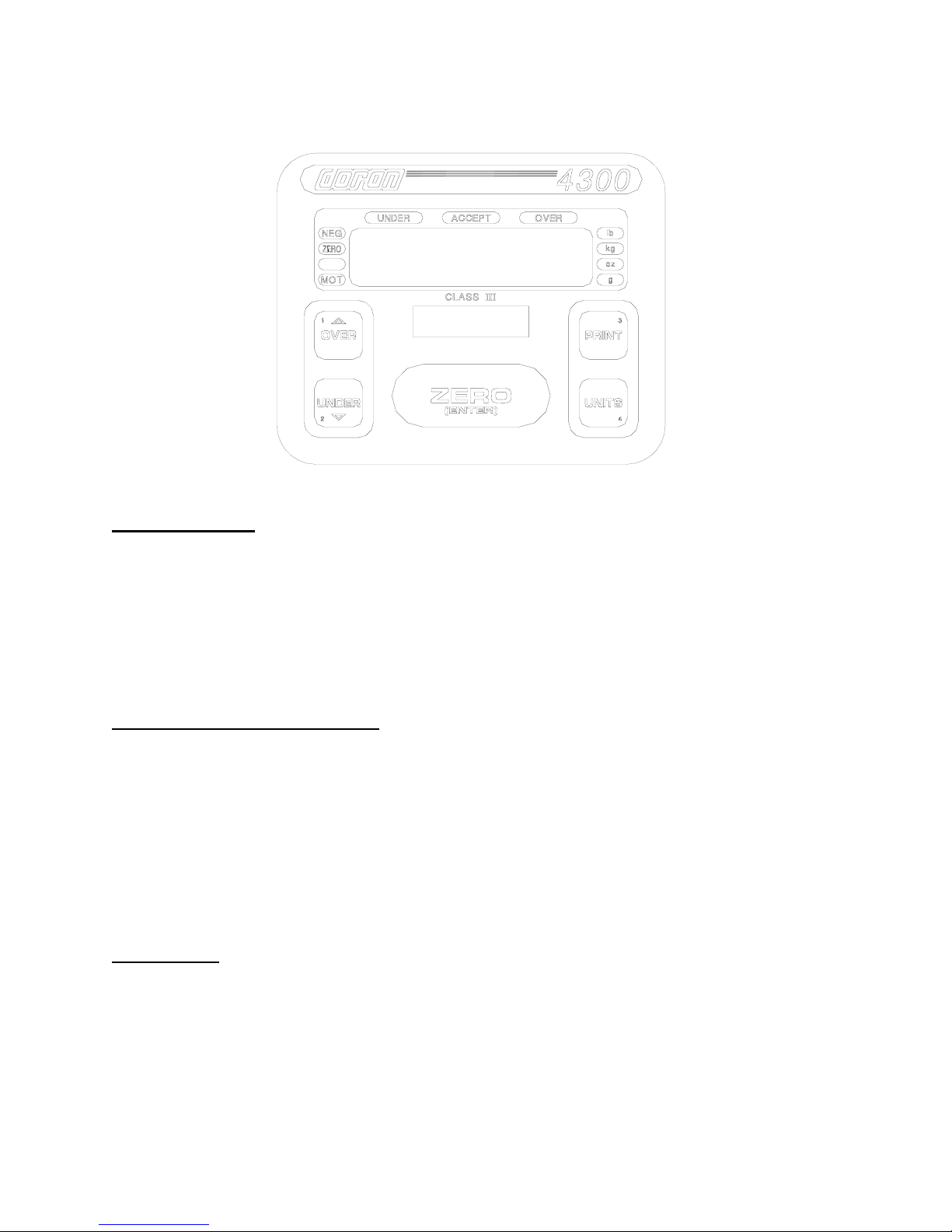
Five Band Checkweighing Operation: (optional configuration)1
1) Remove all items from the scale platter. (If checkweighing to zero, place the target weight
on the scale.)
2) Press ZERO to zero the scale. The weight display should now be zero.
3) Place an item on scale platter and wait for the motion (MOT) indicator to turn off, indicating a
stable weight.
4) If the item is heavier than the "high" limit, the OVER light will flash. If the item is heavier than
the "over" limit but lighter than the "high" limit, the OVER light will turn on. If the item is
lighter than the "low" limit, the UNDER light will flash. If the item is heavier than the "low"
limit but lighter than the "under" limit, the UNDER light will turn on. If the weight is heavier
than the "under" limit but lighter than the "over" limit, the ACCEPT light will light.
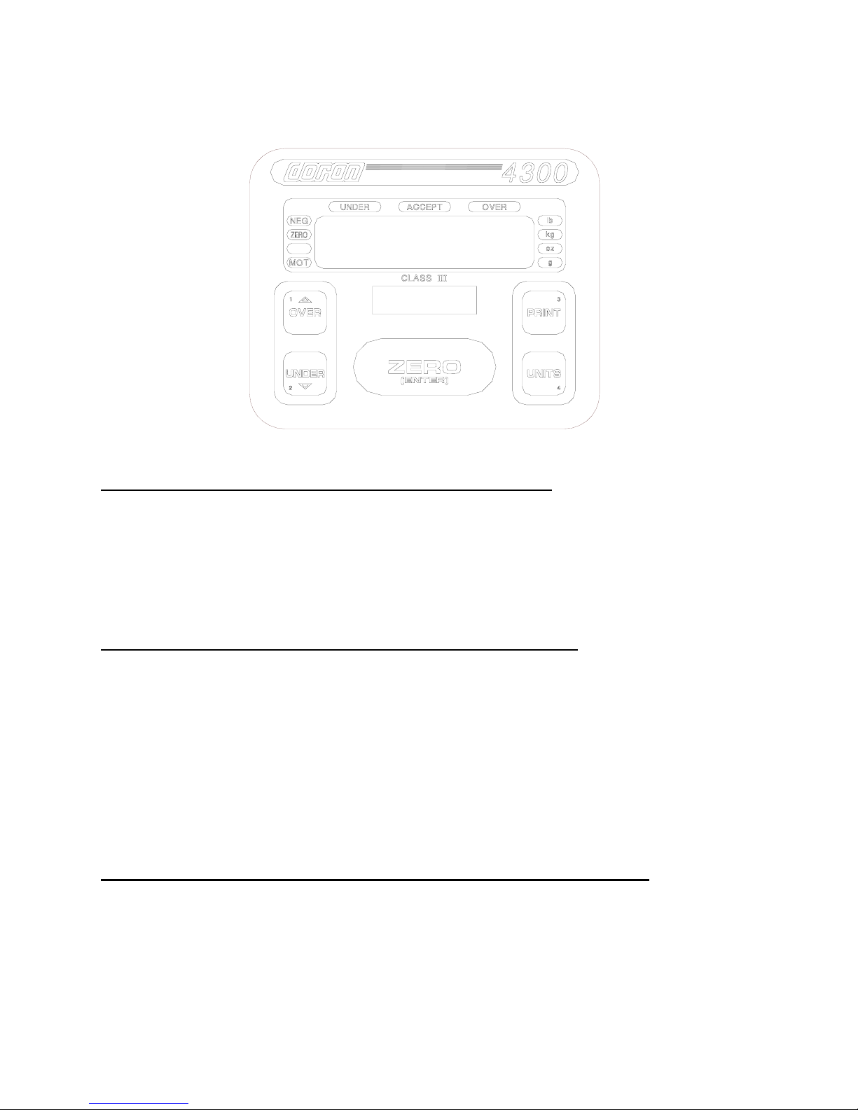
Digital Entry of "HIGH and "LOW" Limits: (optional configuration)1 2
1) Zero the scale.
2) If available, place an item with the desired weight on the scale.
3) Press and hold the OVER button until the lights on each side of the display turn on and the
OVER and ACCEPT lights flash. If "Ent. Cd" appears, enter the password (Refer to the
"Password Entry" section.) and press ZERO.
4) The scale is in the scroll mode. Press either the OVER or UNDER button to increase or
decrease the limit value. Holding the button longer will cause the count to accelerate.
Press UNITS or PRINT to cancel.
5) Once the desired limit is reached, press ZERO to save the limit. The display will read
"donE."
6) To enter the "UNDER" limit, press and release the UNDER button. Then follow step 4 and
5.
Push-button Entry of "HIGH" and "LOW" Limits: (optional configuration)2 3
1) Zero the scale and place an item with the desired "HIGH" weight on the scale.
3) Press and hold the OVER button until the scale displays "donE." The limit has been saved.
4) Remove the "OVER" item and place an item with the desired "UNDER" weight on the scale.
5) Press and hold the UNDER button until the scale displays "donE." The limit has been
saved.
Entering passwords: (optional configuration)
1) The password on the 4300 consists of up to four digits with values from one to four.
Note: The OVER, UNDER, PRINT, and UNITS buttons are numbered from 1 to 4.
Pressing these buttons will enter the associated number.
2) Press the numbered keys in the correct sequence to enter the password (less than four
digits are OK). The password will be displayed on the display as it is entered. If an incorrect
number is pressed, start the number over and the incorrect numbers will shift off the display.
The default password is ZERO (do not press and digits).
3) Press ZERO to accept the password displayed on the scale. If the password is incorrect,
the scale cancels the operation and displays "Abort." Normal weighing then resumes. If the
password is correct, the scale continues the requested activity.
1. The 4300 is shipped from the factory as an "over-accept-under" Checkweigher. The 4300 may be configured for "low-under-
accept-over-high" (5 band) operation. Consult your Doran Authorized Dealer for more details.
2. The 4300 is factory configured for digital limit entry. The 4300 may be configured for push-button limit entry. Consult your
Doran Authorized Dealer for more details.
3. Passwords do not work with push-button limit entry.

9
Quick Setup Guide
Load Cell and Power Connections:
Load cell connections are made through a connector (TB1) located at the bottom of the
main PC Board (See Fig. 2). The power cord connects to a connector (J4) adjacent to
the transformer. These connections are accessible by removing the rear cover. See the
“Specifications and Interconnect Data” section (starting at page 30) for wiring.
Fig. 2: Load Cell / Power connections
The Calibration push button (S1) is located behind the Calibration Access Cover.
Location of the cover is on the back of the tower or bottom of the meter and is held on
with just two bolts for easy access. There are no zero jumpers, span jumpers, switches
or pots to adjust. The calibration push button can be accessed by removing the
Calibration access cover.
Option Connections:
The Remote Switch and Serial Communications connector is found on the left side of
the main PC. board. This connection (P3) is accessed by removing the rear cover.
Newer 4300's will have a 4 screw contact connector (Fig. 3). Like the load cell cable
and power cord, the option cables are passed through watertight fittings mounted on the
bottom of the indicator.

10
Fig. 3: Serial Communications and Remote Push Button Connections
*NOTE: Some 4300s have one less digital ground connection off the bottom
Capacity:
Capacity selection is performed by pressing and release the Calibration
button (S1) to enter the calibrate mode. Press and release UNITS until
"CAP 50" appears on the display (where "50" can be any valid capacity).
Once the CAP prompt appears, press and release ZERO until the desired
capacity is displayed. When finished, press and release the Calibration
button (S1) to exit the Cal menu, the change will automatically be saved.
Once the desired capacity has been selected, place the correct capacity
label behind the capacity window located on the front panel. Secure the
label with tape.
NOTE: On scales with factory installed platforms, the capacity is set at the factory. It will
not be necessary to set the scale capacity.
TXD
REMOTE
SWITCH
*GROUND
CTS /RXD

11
Calibration:
1) The Calibration push button (S1) is located behind the Calibration
Access Cover. Location of the cover is on the back of the tower or bottom
of the meter and is held on with just two bolts for easy access. There are
no zero jumpers, span jumpers, switches or pots to adjust. The calibration
push button can be accessed by removing the Calibration access cover.
2) Momentarily press the Calibration button to enter the CAL menu. Press
and release the UNITS button until "CAL 0" appears on the display.
3) Remove any unnecessary weight from the scale platter. Press ZERO.
The display will count down from 7 to 0 and then show "CAL FS".
NOTE: If "rg Err" appears on the display, the calibration zero is out of range. Press zero
to clear error. Refer to the analog setup section for additional information.
4) Press and release the UNITS button to scroll through the calibration
capacities. Select one of the following:
CAL FS: Full load calibration.
CAL .50: Half load calibration. (50% of full load)
CAL .25: Quarter load calibration. (25% of full load)
CAL .10: 1/10th load calibration. (10% of full load)
If you want to use a weight between 10% and 100% of capacity, but not
exactly 25% or 50%, select the capacity closest to the desired weight (do
not use CAL FS). Then scroll to the exact weight on the display by pressing
the OVER button to go higher or the UNDER button to go lower.
Place the correct weight on the platter. Press ZERO and the display will
count down from 7 to 0. The display will briefly show "donE" and then
return to the weigh mode.
NOTE: If "SPAn E" appears on the display, the calibration span is out of range. Press
zero to clear the error and retry calibration. Refer to the analog setup section for
additional information.
NOTE: Calibration at 10% of capacity has been provided as a convenience to
customers with high capacity scales in remote or inaccessible locations. Scales
calibrated at 10% of capacity are more likely to have significant errors at full
capacity than are scales calibrated at 25% or 50%. Doran Scales recommends
that all scales be calibrated at full capacity whenever possible. 10% calibration
should not be used when calibrating scales for legal for trade applications.
NOTE: On scales with factory installed platforms, the calibration is performed at the
factory. It will not be necessary to calibrate the scale.

12
Analog Setup:
NOTE: Use this section only if you are curious about the load cell output. On scales with
factory installed platforms, the zero and span will lie within permissible limits.
There are no jumpers, pots, or switches to adjust. Raw counts are used to verify
if a load cell will operate within specified limits.
1) Momentarily press the Calibration button (S1) to enter the CAL menu.
Press and release the UNITS button until CAP 50 (where 50 can be any
valid capacity) appears on the display. Follow the procedure to select the
desired scale capacity.
2) Once the correct capacity has been selected, press and release UNITS
until in the raw counts mode. (See setup menu on page 25.)
3) Remove all weight from the scale platform.
4) Record the "no load" counts.
5) Place "Full Load" on the platform and record the "Full Load" counts.
Subtract the "No Load" counts from the "Full Load" counts to calculate
span. Refer to Table 1 and verify that the span falls within the limits
specified for the amount of dead load present. If the readings, are outside
of the limits specified, change dead load or span until the requirements
are met.
6) When using 50%, 25% or 10% of full load to calibrate, calculate the
span for the calibration weight in use. Divide the resulting span by .5, .25
or .1 respectively before comparing the span to the table. The "Full Load"
raw counts (span + dead load) should not exceed 70.0000 counts.
Dead Load Minimum Span
2.0000 to 17.5000 counts 5.3000 counts
17.5000 to 28.0000 counts 11.5000 counts
Table 1. Minimum Span Requirements

13
Detailed Parameter Setup
The Model 4300 has 26 setup and calibration parameters, which can be accessed
through two setup modes. The Configuration mode will allow the user to change the
scale configuration without accessing the scale calibration parameters or breaking the
Weights and Measure seal. This feature makes the 4300 a versatile weighing
instrument capable of meeting most common weighing needs. The Calibration mode
gives access to all parameters.
Entering and Exiting the Configuration Setup Menu:
To enter the Configuration Setup Menu, unplug the scale. Hold the PRINT button
and plug in the scale. The scale will display several startup messages and then the
first menu parameter, "Avg A6", where "A6" can be any valid setting. Press the
UNITS button to access the next menu item. If the password protection mode is on,
the scale will prompt you to enter the password ("Ent Cd") before allowing
parameter access.
To exit the Configuration Setup Menu, scroll through the menu options by pressing
the UNITS button until "donE n" appears. Press ZERO until "donE Y" appears and
then press the UNITS button. The indicator will return to the normal weighing mode.
All menu sections will be saved at that time.
NOTE: No setup information is saved until scale returns to the RUN mode. In the event of a power
failure while in the Configuration Setup Menu, any changes that have been made will be
lost.
Entering and Exiting the Calibration Setup Menu:
To enter the Calibration Setup Menu. Remove the two screws mounting the access
cover. Once opened, momentarily press the Calibration button (S1), located on the
main PC board, to enter the Calibration menu. The indicator will display the first
menu parameter, "CAP 50" (Where 50 can be any valid capacity).
To exit the Calibration Setup Menu, simply press the calibration button (S1) to exit
the menus. The indicator will return to the normal weighing mode. All modified
parameter selections will be saved.
NOTE: No setup information is saved until the scale returns to the RUN mode. In the event of a
power failure while in the Calibration Setup Menu, any changes that have been made will be
lost.

14
Stepping Through the Menu Parameters:
Once the Calibration Setup Menu has been entered, you may step through the
menus by pressing and releasing UNITS. A different display prompt will appear for
each parameter in the menu.
The parameter list on the following pages corresponds to the parameters available in
the Calibration Setup Menu. Items available in both the configuration menu and the
calibration menu will be indicated by a ‡ after the item description. Items available
only in the configuration menu are indicated by ‡‡.
Some of the menu parameters, when changed affect settings of other parameters.
The scale will limit these parameters or automatically set the parameters to meet the
new limits.
Changing a Parameter:
After finding the desired menu item, the parameters for that item may be changed.
Press and release ZERO to step through the parameter list for that item. The list of
choices will repeat if you keep pressing and releasing ZERO. When you have found
the desired setting, press UNITS to go to the next menu item.
Quick Review of Setup Parameters:
Setup parameters for the 4300 may be quickly reviewed without opening the scale.
Remove power and press and hold the ZERO button while you apply power. Hold
the button until the scale begins to scroll through the setup parameters. The button
may be released anytime after the review has begun. After the parameters are
displayed, the scale will return to the normal weighing mode automatically.
Legal for Trade Restrictions:
When the Legal for Trade mode is enabled, it automatically disables some menus
and parameter options. This is done to comply with NTEP requirements. The
menus and parameter sections are shown on the following pages. Those menus
and/or parameters, not available when in the Legal for Trade mode, are marked by
an asterisk *.
Sealing the Scale Calibration Cover and Backplate:
After all setup changes are finished and the indicator is in the normal weighing
mode, re-install the access cover. Make sure the access cover and all the screws
are re-installed in their original locations.
CALIBRATION COVER: Even pressure is applied to 2 bolts. It will prevent any
gaps between the backplate, the gasket, and the case, thereby
preventing debris and moisture from getting into the scale. The
factory recommended torque specification is 6in-lbs.
TOWERS: Even pressure is applied to all 22 bolts. It will prevent any gaps
between the backplate, the gasket, and the case, thereby preventing
debris and moisture from getting into the scale. The factory
recommended torque specification is 6in-lbs.
METERS: Completely tighten the four backplate screws. The meter has a built
in design that will prevent crushing the gasket from overtightened
bolts. The average factory torque setting is between 25 to 30in-lbs.

15
Setup Menus Explained (In order of occurrence)
Capacity Setup Menu
CAP Capacity Select Menu
Allows the selection of scale capacity.
5 5 pounds
6 6 pounds
10 10 pounds
15 15 pounds 2, 3
20 20 pounds 3
25 25 pounds 3
30 30 pounds 3
50 50 pounds
60 60 pounds
100 100 pounds
150 150 pounds 2, 3
200 200 pounds 3
250 250 pounds 3
300 300 pounds 3, 4
500 500 pounds 1, 2, 3, 4
600 600 pounds 1, 2, 3, 4
1. 1000 pounds 1, 2, 3, 4
1.5 1500 pounds 1, 2, 3, 4
2. 2000 pounds 1, 2, 3, 4
2.5 2500 pounds 1, 2, 3, 4
3. 3000 pounds 1, 2, 3, 4
5. 5000 pounds 1, 2, 3, 4
6. 6000 pounds 1, 2, 3, 4
10. 10,000 pounds 5
15. 15,000 pounds 5
20. 20,000 pounds 5
25. 25,000 pounds 5
30. 30,000 pounds 5
50. 50,000 pounds 5
60. 60,000 pounds 5
100. 100,000 pounds 5
1) No lb-oz display for this capacity in standard resolution.
2) No lb-oz display for this capacity in precision resolution.
3) No lb-oz display for this capacity in super precision resolution.
4) No grams display for this capacity.
5) Pound - kilograms display only at this capacity

16
Calibration Menu
CAL Zero Calibration Mode.
0 Calibration Zero
Press ZERO to perform calibration of the scale zero.
Successful calibration is indicated by "donE"
NOTE: The scale will automatically adjust the offset and gain to compensate for dead
load and span. When making these adjustments, the scale may ask you to repeat zero
calibration immediately after performing a zero calibration or after a span calibration.
Successful calibration is indicated by "donE"
CAL Span Calibration Mode.
(Does not appear if CAL 0 is not activated.)
FS Full load calibration.
0.5 Half capacity calibration.
0.25 Quarter capacity calibration.
0.1 1/10th of capacity calibration.
XXXXXX By pressing the UNITS button first and then the
OVER or UNDER buttons, any weight value can be
dialed in for calibration.
NOTE: "XXXXXX" will be the dialed in weight value.
* NOTE: For maximum accuracy, Doran Scales recommends that all scales be
calibrated at full capacity. When location or installation make it difficult to bring full
capacity weights to the scale, calibration with as little 10% of capacity is possible.

17
Digital Filter Setup Menu
Avg Averaging mode
Determines the number of samples to average
A0 Stabil-izer ©auto averaging. All readings are
averaged. Display updates 10 times a second.
A9 Stabil-izer ©auto averaging. All readings are
averaged. Display updates 9 times a second.
A7 Stabil-izer ©auto averaging. All readings are
averaged. Display updates 7 times a second.
A6 Stabil-izer ©auto averaging. All readings are
averaged. Display updates 6 times a second.
A5 Stabil-izer ©auto averaging. All readings are
averaged. Display updates 5 times a second.
A4 Stabil-izer ©auto averaging. All readings are
averaged. Display updates 4 times a second.
A3 Stabil-izer ©auto averaging. All readings are
averaged. Display updates 3 times a second.
2 Fixed averaging 2 readings are averaged. Display
updates 20 times a second.
4 Fixed averaging 4 readings are averaged. Display
updates 10 times a second.
8 Fixed averaging 8 readings are averaged. Display
updates 5 times a second.
16 Fixed averaging 16 readings are averaged. Display
updates 3 times a second.
32 Fixed averaging 32 readings are averaged. Display
updates 1½ times a second.
Automatic Zero Tracking Setup Menu
AZt Automatic Zero Tracking Range
Small weights within the specified number of
divisions are automatically zeroed.
oFF Zero tracking is off. No automatic zeroing.
0.5 Zero tracking to within 0.5 division.
1 * Zero tracking to within 1.0 division.
3 *Zero tracking to within 3.0 divisions.
* NOTE: The Legal for Trade mode disables some options and selections listed above.
These items have been indicated by an asterisk.

18
Motion Aperture Setup Menu
m.A. * Motion aperture *
Determines how many divisions consecutive
readings must change before the scale is
considered to be in motion.
1 1 division change must be seen to enter motion.
3 3 division change must be seen to enter motion.
5 5 division change must be seen to enter motion.
Start Up Zero Setup Menu
SU0 * Start Up Zero
Controls the start up zero status.
on Zeros on the first stable reading on power up.
oFF Loads the calibration zero for zero reference
* NOTE: The Legal for Trade mode disables some options and selections listed above.
These items have been indicated by an asterisk.
Latching Zero Request Setup Menu
Zod Zero on Demand
Enables or disable zero latching.
on If ZERO is pressed, it is saved until the scale
becomes stable.
oFF If the scale is in motion, the zero request is
discarded.
Latching Print Request Setup Menu ‡
Pod Print on Demand
Enables or disables print latching.
on If PRINT is pressed, the print request is saved until
the scale becomes stable.
oFF If the scale is in motion, the print request is
discarded.

19
Printer Data Output Setup Menu ‡
d.o. Data Output Mode
Determines when serial data will be sent.
t.o.d. Transmit on demand. Print when the PRINT
button is pressed.
C.P. Continuous Print. Print when display is updated.
A.P.1 Auto Print 1. Print once only when scale goes stable.
A.P.2 Auto Print 2. Print once only when scale goes stable.
Scale must return to zero before it can print again.
Output Formats Setup Menu ‡
For. Data Input / Output Format
Defines the appearance of the serial data sent.
F0 Basic output format.
(See the Data Communication section for details)
F1 Enhanced Output includes Checkweigh status.
d0 Basic Dual Print Format. Includes Kilogram weight.
d1 Basic Dual Print Format. Includes Kilogram weight
and Checkweigh status.
SS0 Basic Output for Doran Model SSP printer.
SS1 Enhanced Output for Doran Model SSP printer.
Baud Rate Setup Menu ‡
br. Baud Rate Setup
Determines baud rate for serial data.
12 1200 baud (bits per second)
24 2400 baud (bits per second)
48 4800 baud (bits per second)
96 9600 baud (bits per second)
14.4 14,400 baud (bits per second)
Other manuals for 4300
1
Table of contents
Other Doran Scales Scale manuals

Doran Scales
Doran Scales DS6100 User manual

Doran Scales
Doran Scales DS6150 User manual

Doran Scales
Doran Scales PC400 User manual

Doran Scales
Doran Scales DS7100 User manual

Doran Scales
Doran Scales DS600 User manual

Doran Scales
Doran Scales 4300 User manual

Doran Scales
Doran Scales DS7060 User manual

Doran Scales
Doran Scales 2200CW Series User manual

Doran Scales
Doran Scales DS9100 User manual

Doran Scales
Doran Scales DS4100 User manual