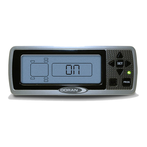
Doran 360HD User manual

Protected by US Patent Nos. 8,183,992; 7,940,164; 7,944,347 and Other Pending Patents
Manufacturing LLC
Please read this manual carefully
before using this product.
360HD
Monitors up to 36 different wheel positions
(This manual can be referred to the HD/HDR/HDRB/HDJ/HDJB models)
USER MANUAL
The DORAN 360HD is designed solely to monitor tire pressure. It is not
designed to provide warning of a potential or actual tire blowout.
The National Highway and Traffic Safety Administration considers a tire flat
when the pressure is 25% below the tire manufacturer’s recommended operating
pressure.

DPM-HD Version 1 2019-01-28 2
TABLE OF CONTENTS
I. INTRODUCTION ................................................................................................................................... 3
SYSTEM COMPONENTS ................................................................................................................. 4
GLOSSARY OF TERMS ................................................................................................................... 5
II. SETUP AND INSTALLATION ............................................................................................................ 6
1. INSTALLING THE MONITOR ................................................................................................. 6
2. PROGRAMMING THE MONITOR ........................................................................................... 7
A. PROGRAMMING THE SENSOR LOCATION..................................................... 7
B. BASELINE PRESSURE PROGRAMMING .......................................................... 9
C. PROGRAMMING THE DATE AND TIME FOR STORED ALARM HISTORY
INFORMATION............................................................................................................... 11
D. PROGRAMMING THE UNIT OF MEASURE.................................................... 12
E. DELETE SENSOR LOCATION ........................................................................... 13
F. HIGH PRESSURE ALARM PROGRAMMING .................................................. 14
III. INSTALLING THE SENSORS ON THE VEHICLE. ....................................................................... 15
IV. ALARM MODES ............................................................................................................................... 16
V. NORMAL MODE ACCESSORY FUNCTIONS ............................................................................... 19
1. DROP AND HOOK FEATURE ................................................................................................ 19
2. FACTORY RESET .................................................................................................................... 19
3. STORE ALARM INFORMATION .......................................................................................... 20
4. BACKLIGHT OPERATION ..................................................................................................... 21
VI. FAQs AND TIPS ................................................................................................................................ 21
1. FREQUENTLY ASKED QUESTIONS .................................................................................... 21
2. TIPS ........................................................................................................................................... 23
3. LIMITED WARRANTY ........................................................................................................... 25
4. SPECIFICATIONS .................................................................................................................... 26
VII. COMPLIANCE AND DISPOSAL INFORMATION ...................................................................... 27
1. FCC COMPLIANCE STATEMENT ........................................................................................ 27
2. CANDIAN REGULATORY STATEMENT ............................................................................ 27
3. DISPOSAL AND RECYCLING INFORMATION .................................................................. 27
VIII. OPTIONAL ACCESSORIES .......................................................................................................... 28

I. INTRODUCTION
The DORAN 360HD is a real-time, wireless, electronic tire pressure monitoring system
designed for heavy duty trucks. The DORAN 360HD can monitor pressures from 10 to 188 psi
and is capable of displaying current tire pressures, whether the vehicle is moving or stationary.
Although the 360HD will not prevent tires from losing pressure or failing, low pressure is the
leading cause of premature tire failure. Additionally, the DORAN 360HD has a built in high
temperature alarm, activated at 175°F, that can provide excessive heat warnings which can
identify other potential wheel problems. The 360HD can be used on all pneumatic tires and can
provide an early notification of potential problems and assist with proper tire pressurization
maintenance.
The DORAN 360HD System consists of two basic components: Valve Stem Tire Sensors and
a Monitor. The wireless sensors transmit coded RF signals to the monitor.
The monitor will then interpret the data, display current tire pressure readings, and alert the
driver with audible and visual feedback if there is a pressure drop or excessive heat. The
system will provide pressure alerts at 2 levels: 12.5% below baseline pressure and greater
than 25% below baseline pressure. The high temperature alarm is activated at temperatures of
175°F and above. When used properly, the DORAN 360HD will inform the driver of tire
pressure or temperature issues so the operator has the opportunity to make necessary
adjustments before a serious problem occurs.
Tires and valve stems should be inspected thoroughly prior to installation of the DORAN
360HD System to ensure that they are in good condition. It is not uncommon to find valve
stems that need replacing or low tire inflation when installing the DORAN 360HD system.
DORAN recommends that rubber valve stems be replaced with brass or stainless steel stems
as some rubber stems have been found to be inferior and can cause premature failure.
Regular tire and valve stem visual inspections are recommended. A damaged sensor,
tire, or valve stem can cause pressure loss. Inspect regularly. If faults are repeatedly
observed, discontinue use of the system and contact DORAN Mfg. Toll Free 1-866-816-
7233.
The 360HD
cannot prevent tire/wheel overload. Overloading any tire is extremely
dangerous and can cause the failure of any suspension component, not just tires! The only
way to detect overloading is to weigh the vehicle. A vehicle should never be operated if the
weight on any wheel is greater than the design specification. Even a correctly inflated tire can
fail if overloaded.
Tires can fail for other reasons besides low pressure or overloading. Stay alert and watch
for other tire problems that may be indicated by unusual noises, vibrations, uneven tread wear,
or bulges on the tire. If any of these symptoms occur, have the tires checked immediately by a
professional!

DPM-HD Version 1 2019-01-28 4
SYSTEM COMPONENTS
Hook & Loop
pads for
installing
Monitor
√ ×
Nylon wire tie
kit
√ √
Sensor for
each tire
purchased
× ×
A
ntenna Kit
(purchased
Separately)
× ×
If you are missing any of these components, DO NOT proceed with the installation.
Contact the manufacturer for any missing or replacement parts.

DPM-HD Version 1 2019-01-28 5
GLOSSARY OF TERMS
Normal Mode: When the monitor is monitoring all programmed sensors and there are not
any faults, the monitor will display a Green Means Good™ indicator light and the display will
show “on” (Black box products don’t have the Green Means Good™ indicator light).
Alert Mode: When the monitor has received a signal that is outside of the parameters of the
“Normal Operation” an alert will be displayed with icons describing the fault along with an
audible beeping sound (Audible alarm is not available on the “black box” products). Pressing
the Set or Program buttons can turn off the audible alarm.
Baseline Air Pressure: The normal operating pressure setting that is programmed into the
monitor for each tire position. The monitor will calculate all alarms from this setting. The
baseline pressure should ALWAYS be set when tires are at ambient temperature as
temperatures directly affect pressure levels.
RF: The term used to identify Radio Frequency signals.

DPM-HD Version 1 2019-01-28 6
II. SETUP AND INSTALLATION
DORAN suggests that all users install a remote antenna to receive maximum performance
from the system
1. INSTALLING THE MONITOR
The 360HD (Standard display) comes with a hook and loop mounting option. Other
mounting options include: sun visor mount, windshield mount, dash mount, and
pedestal mount. If you are using the hook and loop pads, clean all mounting surfaces
thoroughly with alcohol to remove any grease, dust, or oils that could prevent proper
adhesion. Choose the monitor back panel which
will work best for the mounting configuration
and remove the appropriate breakaway tab to
allow the cord to exit in the desired direction.
(see Figure 1-1).
In order for the monitor to operate as intended, all monitor connections should be
hard wired from the monitor to the vehicle’s electrical system. There are three wires
in the monitor harness. Red is 12/24-volt positive constant connection. This should
be connected to a 12/24-volt power source that is always “On”. The Blue wire is the
“Switched” 12/24-volt positive connection or “Ignition”. This wire should only be “On”
when the key is in the “On” position. The BLACK wire is to be connected to ground.
These connections will allow the monitor to receive signals when the vehicle is not
running and update the monitor in real time. When “Ignition” is turned on, you will
have the most up to date information for all tire conditions before the next trip is
started.
The monitor is fused internally, however some installers would still prefer to
install an inline fuse for precautions. We suggest an optional 2-amp slow blow fuse
be used for this purpose.
Figure
1-1

DPM-HD Version 1 2019-01-28 7
2. PROGRAMMING THE MONITOR
In order for the monitor to report tire information the user, sensor serial numbers
and baseline pressures for each tire location need to be programmed. This is done
by following the steps below. Note, “black box” products do not have an audible
alarm or feedback.
Do not install sensors until all programming is completed and the monitor is
returned to the normal operation mode.
A. PROGRAMMING THE SENSOR LOCATION
1) Ensure that the power is on. Upon first power up, the display will show “
n
SP which
stands for “No Sensors Programmed”. Note that this message can also appear if
programmed sensors have not transmitted to the monitor. It could take up to 8
minutes for all sensors to transmit their information. The Programming mode will
need to be accessed to add sensors to the monitor. Be sure to leave the sensors off
the valve stems until the programming is completed to facilitate the process.
2) Press and hold the “P” button for approximately 5
seconds. When the monitor screen displays the
program mode, the “P” button can be released. All
available tire positions will now be displayed on the
screen. See Figure 2-1. The monitor can be set up to
display a motor home pulling a car or trailer, or a car /
truck pulling a trailer.
“P” is used to enter the program
modes. Also used to silence alarms.
“S” is used to lock in selections
during programming. Used to turn
on and off the backlight.
(4) Arrow buttons are used to
navigate the screen and select
values in the program mode
Fi
g
ure 2-1

DPM-HD Version 1 2019-01-28 8
3) Be sure to properly program sensors to the desired positions.
Use the diagram in Figure 2-3 to record the three digit serial
numbers (See Figure 2-2 for the three digit number location)
and corresponding tire positions for programming.
4) Select the desired tire position using the arrow
buttons. Hold down the “S” button until the first of the
three dashes begins to blink (See Figure 2-4).
5) Input the three digit sensor serial number located on the sensor using the “Up” and
“Down” arrows to adjust the numeric value and the “Left” and “Right” arrows to
change the digit being adjusted (See Figure 2-2 for
the three digit number location). Once the serial
number is entered, press and hold the “S” button
for 3 Seconds until the number flashes and audible
beeps are heard. See Figures 2-5, 2-6, and 2-6a.
Fi
g
ure 2-4
Fi
g
ure 2-5
Figure 2-3
Figure 2-2

DPM-HD Version 1 2019-01-28 9
6) Once the tire serial number has been programmed successfully, a new position will
be highlighted to input another sensor serial number. Continue to program the
remaining sensors by repeating the above steps 4 and 5.
7) Once all sensors have been programmed, press the “P” button momentarily to
move to the Baseline Pressure Settings. The monitor will now display the screen
shown in Figure 2-7. Note, press and hold “P” for 5 seconds to exit programming
mode and return to normal operating mode at any time.
B. BASELINE PRESSURE PROGRAMMING
NOTE: To enter into Baseline Pressure Programming
Mode from the Normal Operation Screen, press and hold
the “P” button for 5 seconds until the “PROGRAM”
screen is displayed. Then press the “P” button once to
access the Baseline Pressure Programming screen
“PRESSURE PSI PROGRAM” (See Figure 2-7).
The baseline pressure has been set in the factory at 100-psi for all wheel positions.
DORAN recommends that all baseline pressures are set to the same pressure
levels recommended by the tire manufacturer. If baseline pressures need to be
changed, or a new sensor is programmed, then follow the procedure below. Otherwise,
press “P” once to proceed to Date and Time Settings.
Fi
g
ure 2-7
Fi
g
ure 2-6 Fi
g
ure 2-6a

DPM-HD Version 1 2019-01-28 10
The monitor should now be displaying the wheel
positions available for Baseline Pressure adjustment
(See Figure 2-8). The text on the screen will contain
different units of measure (PSI, Bar, or kPa) depending
on which pressure unit is selected in the settings of the
monitor. The Baseline Pressure may be set anywhere
from 10 to 188 PSI. Each wheel position can be set with a
different Baseline Pressure if needed.
1) Using the same controls as sensor serial number programming, use the arrow
buttons navigate to the desired tire position. Press and hold the “S” button for 3
seconds. This will cause the first dash or number to blink (See Figure 2-9). Use the
“Up” and “Down” arrows to adjust the numeric value and the “Left” and “Right”
arrows to change the digit being adjusted. Once the
Baseline Pressure has been set, press and hold the
“S” button for 3 Seconds until the number flashes
twice and audible beeps are heard. (Audible alarm is
not available on the “black box” products)
2) For values less than 100, the first digit will need to be 0 followed by the two digit
Baseline Pressure value. Example: For a Baseline Pressure of 95 PSI, the value
would be entered as “095”.
3) If additional Baseline Pressures need changed, use the arrow keys to navigate to
the next position to be programming and repeat step 1. If all Baseline Pressure
have been set, press “P” once to move to the Date and Time Settings. Note, press
and hold “P” for 5 seconds to exit programming mode and return to normal
operating mode at any time.
4) To set the a global Baseline Pressure, press and hold “S” on any tire position, enter
in the desired global Baseline Pressure, and press “S” and “P” simultaneously for 3
seconds.
Fi
g
ure 2-8
Figure 2-9

DPM-HD Version 1 2019-01-28 11
C. PROGRAMMING THE DATE AND TIME FOR STORED ALARM
HISTORY INFORMATION
NOTE: To enter into the Date and Time Programming
Mode from the Normal Operation screen, press and hold
the “P” button for 5 seconds until the “PROGRAM” screen
is displayed. Then press the “P” button twice to access
Date and Time Programming Mode (See Figure 2-10).
NOTE: Stored alarms are not available on the “black box” products.
1) To adjust the Year (Y), Press and hold the “S” button
for 3 seconds until the first digit begins to flash (See
Figure 2-11). Use the “Up” and “Down” arrows to
adjust the numeric value corresponding to the last
two digits of the calendar year. The “Left” and “Right”
arrows are used to change the digit being adjusted.
Once the Year (Y) has been entered, press and hold
the “S” button for 3 seconds to proceed to the Month
(M) setting (See Figure 2-12).
2) To adjust the Month (M), Press and hold the “S”
button for 3 seconds until the first digit begins to
flash. Use the “Up” and “Down” arrows to adjust the
numeric value and the “Left” and “Right” arrows to
change the digit being adjusted. Once the Month (M)
has been entered, press and hold the “S” button for 3
seconds to proceed to the Day (D) setting (See
Figure 2-13).
3) To adjust the Day (D), Press and hold the “S” button
for 3 seconds until the first digit begins to flash. Use
the “Up” and “Down” arrows to adjust the numeric
value and the “Left” and “Right” arrows to change the
digit being adjusted. Once the Day (D) has been
entered, press and hold the “S” button for 3 seconds
to proceed to the Hour (H) setting (See Figure 2-14).
Figure 2-10
Figure 2-13
Fi
g
ure 2-14
Fi
g
ure 2-12
Figure 2-11

DPM-HD Version 1 2019-01-28 12
4) To adjust the Hour (H), Press and hold the “S” button
for 3 seconds until the first digit begins to flash. Note:
The Hour (H) will be displayed in a 24-Hour Format.
Use the “Up” and “Down” arrows to adjust the numeric
value and the “Left” and “Right” arrows to change the
digit being adjusted. Once the Hour (H) has been
entered, press and hold the “S” button for 3 seconds to
proceed to the Minute (M) setting (See Figure 2-15).
5) To adjust the Minutes (M), Press and hold the “S” button for 3 seconds until the first
digit begins to flash. Use the “Up” and “Down” arrows to adjust the numeric value
and the “Left” and “Right” arrows to change the digit being adjusted. Once the
Minute (M) has been entered, press and hold the “S” button for 3 seconds to
proceed back to the beginning of the Date and Time
Programing screen starting at the Year (Y) setting
(See Figure 2-10). To proceed to the Unit of Measure
Programming screen, press the “P” button once. Note,
press and hold “P” for 5 seconds to exit programming
mode and return to normal operating mode.
D. PROGRAMMING THE UNIT OF MEASURE
NOTE: To enter into the Unit of Measure Programming
Mode from the Normal Operation screen, press and hold
the “P” button for 5 seconds until the “PROGRAM” screen is
displayed. Then press the “P” button three times to access
the Unit of Measure Programming Mode (See Figure 2-17).
The default unit of measure is factory set to PSI. The Doran
monitor can also display pressure in BAR and kPa (See
Figure 2-18 and 2-19). Use the “Left” and “Right” arrow keys
to select the desired units. Press and hold the “S” button the
selection blinks and audible beeps are heard. To proceed to
the Delete Tire Sensor Programming screen, press the “P”
button once. Note, press and hold “P” for 5 seconds to exit
programming mode and return to normal operating mode.
Figure 2-17
Fi
g
ure 2-18
Figure 2-15
Figure 2-16
Fi
g
ure 2-19

DPM-HD Version 1 2019-01-28 13
E. DELETE SENSOR LOCATION
This step is only used when a sensor is to be removed from the memory of the monitor.
This would also be used to remove a sensor from one position and locate it to a different
position.
NOTE: To enter into the Delete Sensor Location
Programming Mode from the Normal Operation screen,
press and hold the “P” button for 5 seconds until the
“PROGRAM” screen is displayed. Then press the “P”
button four times to access the Delete Sensor Location
Programming Mode (See Figure 2-20).
In the Delete Sensor Location Programming Mode, all programmed sensors will be
displayed. If no sensors need to be deleted, proceed to the next screen by pressing the
“P” button once.
To delete a sensor, select the sensor using the arrow buttons (Figure 2-21). Hold down
the “S” button until the three digits blink and audible beeps are heard. The sensor will
now be removed (Figure 2-22). When all desired sensors are deleted, proceed to the
High Pressure Alarm Programming Mode by pressing the “P” button once. To program a
deleted sensor to a different location, or add new sensors to the monitor’s memory,
press the “P” button twice to enter into the Programming Sensor Location mode.
Fi
g
ure 2-21 Figure 2-22
Figure 2-20

DPM-HD Version 1 2019-01-28 14
Figure 2-25
Fi
g
ure 2-26
F. HIGH PRESSURE ALARM PROGRAMMING
NOTE: To enter into the High Pressure Alarm
Programming Mode from the Normal Operation screen,
press and hold the “P” button for 5 seconds until the
“PROGRAM” screen is displayed. Then press the “P”
button five times to access the High Pressure Alarm
Programming Mode (See Figure 2-23).
The High Pressure Alarm Programming mode allows the user to enable (Figure 2-24) or
disable (Figure 2-23) the high pressure alarm. A high pressure alarm will occur when a
pressure is recorded at 25% higher than the baseline pressure setting. High
temperatures can cause elevated pressures. This alarm can provide early detection of a
possible temperature issue. Use the “Left” and “Right” arrows to enable or disable the
high pressure alarm. Press and hold the “S” button until the screen flashes and audible
beeps are heard.
G. BAUD RATE SELECTION (J1939 PRODUCTS ONLY)
NOTE: To enter into the Baud Rate Selection Mode from the Normal Operation screen,
press and hold the “P” button for 5 seconds until the “PROGRAM” screen is displayed.
Then press the “P” button six times to access the Baud Rate Selection Mode (See
Figure 2-25).
The Baud Rate Selection mode allows the user to select a
250k or 500k baud rate for J1939 products. It is very
important that the selected baud rate matches the vehicle’s
baud rate. Failure to do so could cause operational issues
with the vehicle. Use the “Left” and “Right” arrows to select
the b25 for 250k (Figure 2-25) or b50 for 500k (Figure 2-26).
Press and hold the “S” button until the screen flashes and
audible beeps are heard.
Fi
g
ure 2-23
Figure 2-24

DPM-HD Version 1 2019-01-28 15
III. INSTALLING THE SENSORS ON THE VEHICLE.
The monitor should now be turned on and it should be in the normal operation mode.
Note, it could take up to eight (8) minutes after power up for the monitor to receive all of
the updated signals from the tire sensors.
Before installing tire sensors, inspect all of the valve stems. Replace any cracked or
defective valve stems. If replacements are necessary, Doran suggests replacing the
valve stems with brass or stainless steel components for improved life.
lf sensors have not been programmed to the monitor, or signals
are not received by the monitor after first installed the screen
will display “
ns
P
” (see Figure 3-1).
1. Once all sensors have been programmed into the monitor, they will need to be installed
in the proper tire positions on the vehicle.
The sensor should be tightened only by hand. Never use a tool to tighten the
sensors as this could cause damage to the valve stems and/or the tire sensors. If
needed, leaks can be identified using a soapy solution. The monitor should now begin to
display wheel positions and tire pressures.
2. If all sensors are reporting pressures within the baseline
settings, the monitor will display “on”. The Green Means
Good™ indicator light will also illuminate (See Figure 3-
2). Note, the “black box” products do not have a Green
Means Good™ indicator light. The Doran 360HD Tire
Pressure Monitor System is now ready for use.
3. If any of the tire pressures are outside of the baseline pressure settings, an alarm will be
displayed, and audible alarm will sound, and the red alarm LED will illuminate. See
section IV for all alarm mode scenarios. Note, “black box” products do not have an
audible alarm.
Fi
g
ure 3-2
Fi
g
ure 3-1

DPM-HD Version 1 2019-01-28 16
IV. ALARM MODES
NOTE: Alerts indicate that the vehicle is being operated in a dangerous condition.
When an alarm is triggered, STOP and check the tire(s) as soon as safely
possible and investigate. The warning will continue to be reported as long
as the malfunction exists.
NOTE: When an alarm occurs, the audible alarm will sound. Pressing any button
will silence the audible alarm but will not clear it (Audible alarm is not
available on the “black box” products).
The DORAN 360HD has six types of alarm modes. The warning levels are:
Under Pressure – Tire pressure is 12.5% or more below the programmed baseline
air pressure.
o When an Under Pressure alarm is reported, the backlight of the monitor
screen will illuminate. The Green Means Good™ indicator light will turn off,
the red warning LED will begin to flash, and the audible alarm will sound at a
rate of one flash/beep per second. The tire
position with the alarm condition will be
highlighted, the current pressure reading
displayed, and the words “LOW PRESSURE”
will be displayed on the monitor (See Figure 4-1)
Extreme Under Pressure – Tire pressure is 25% or more below the programmed
baseline air pressure.
o The National Highway and Traffic Safety Administration considers a tire flat
when the pressure is 25% below the tire manufacturers’ recommended
operating pressure
o When an Extreme Under Pressure alarm is reported, the backlight of the
monitor screen will illuminate. The Green Means Good™ indicator light will
turn off, the red warning LED will begin to flash, and the audible alarm will
sound at a rate of two flashes/beeps per second. The tire position with the
Figure 4-1

DPM-HD Version 1 2019-01-28 17
Figure 4-2
alarm condition will be highlighted, the low pressure displayed, and the
words “LOW PRESSURE” will be displayed on the monitor (See Figure 4-1).
o Driving on a significantly under-inflated tire can cause the tire to overheat
and lead to tire failure. Under-inflation also reduces fuel efficiency and tread
life which can potentially affect the vehicle’s handling and stopping ability.
Fast Leak Warning – Occurs when 4.5 PSI or more is lost from the tire in less than
16 seconds.
o When a Fast Leak alarm is reported, the backlight of the monitor screen will
illuminate. The Green Means Good™ indicator light LED will turn off, the red
warning LED will begin to flash, and the audible alarm will sound at a rate of
one flash/beep per second. The tire position with the alarm condition will be
highlighted and the words “FAST LEAK”
will be displayed on the monitor (See
Figure 4-2). This alarm will only be
displayed during the fast leak and will be
cleared when the air ceases to leak from the
tire.
High Pressure (Optional Alarm) – Tire pressure is 25% or more above the
programmed baseline air pressure.
o If the High Pressure alarm is activated and occurs, the Green Means Good™
indicator light will turn off, an audible alarm will sound at a rate of one beep
per second, and HIGH PRESSURE will be displayed on the monitor screen.
o This alarm can be generated by a dragging brake, bad wheel bearing,
extreme temperature conditions, or other mechanical failures.

DPM-HD Version 1 2019-01-28 18
Fi
g
ure 4-3
Figure 4-4
Lost Signal – Occurs when the monitor does not receive the RF signal from a
sensor.
o If the monitor is unable to receive a signal
from a sensor for more than 60 minutes, an
alarm will be displayed for that sensor (See
Figure 4-3).
Hot – Sensor temperature is above 175℉ (80℃). This could indicate suspension
or wheel component malfunction.
o When a Hot alarm occurs, HOT will be displayed on the monitor (See Figure
4-4). NOTE, an Under Pressure or Extreme Under Pressure alarm will over-
ride a “HOT” alarm because of the potential danger of a low pressure tire.
When the HOT warning appears, STOP and check your tire(s) as soon as safely
possible, and check for the possible cause.
NOTICE: A “LOW PRESSURE” warning will over-ride a “HOT” warning because of
the potential danger of a low pressure tire.

DPM-HD Version 1 2019-01-28 19
V. NORMAL MODE ACCESSORY FUNCTIONS
1. DROP AND HOOK FEATURE
The Drop and Hook feature allows the operator of the vehicle to customize which sets
of tire sensors the monitor displays. This is useful when a trailer or towed car are not
attached to the vehicle and do not need displayed. The following steps are used to
adjust the display configuration:
1) Press and hold the “Left” and “Rear” arrow
buttons for 3 seconds to enter the Drop and
Hook Programming Mode.
2) All of the programmed wheel positions will be
displayed (see Figure 5-1).
3) Use the “Left” and “Right” arrow buttons to
cycle through the display configuration (see
Figure 5-2 and 5-3).
4) When the desired display configuration is
selected, press and hold the “Left” and “Right”
arrow buttons for 5 seconds. This will confirm
the configuration and return the monitor to
Normal Operation mode. Note, when you
change the display configuration it may take up
to 8 minutes for the monitor to receive all of the
sensor transmissions and update the display.
2. FACTORY RESET
Warning, this will return the monitor to the factory default settings and erase all
programming! Verify that this is desired before proceeding. To return the monitor to
factory default settings, press and hold the “P” button for 30 seconds.
Be sure this is what you want to do before you proceed!
Figure 5-3
Figure 5-2
Figure 5-1

DPM-HD Version 1 2019-01-28 20
Fi
g
ure 6-3 Fi
g
ure 6-4
Fi
g
ure 6-2
3. STORE ALARM INFORMATION
The Doran 360HD Monitor has the ability to store the last 31 alarm faults. These
recorded faults cannot be erased; they will only be replaced by new alarms. This can
be a very useful tool for the over the road trucking industry or any application where an
alarm history is necessary.
To access the stored alarms, press and hold the “P” and “S”
button together for 3 seconds. A number 0 will be displayed on
the screen (See Figure 6-1) indicating the latest fault. You can
cycle through the other stored alarms by using the “Left” and
“Right” arrow keys. If no buttons are pressed within 1 second,
the monitor will begin to show the alarm details. See an
example stored alarm below:
Figure 6-2 - Air pressure of the alarm
Figure 6-3 - M07 represents the 7th Month of the Year or July.
Figure 6-4 - d04 represents the 4th Day of the Month
Figure 6-5 - Y06 represents the Year 2006
Figure 6-6 - h14 represents 2:00 PM (24-hour clock)
Figure 6-7 - m33 Represents 33 minutes
To return to Normal Operating mode press and hold the “P” and “S” buttons together
for three seconds.
Figure 6-1
Fi
g
ure 6-5 Fi
g
ure 6-6 Fi
g
ure 6-7
Other manuals for 360HD
1
Table of contents
Other Doran Measuring Instrument manuals
Popular Measuring Instrument manuals by other brands

Nidec
Nidec MF-2 Operation manual

Ludlum Measurements
Ludlum Measurements 30 Series manual

Tower Hobbies
Tower Hobbies Expanded Scale Voltmeter instructions

Labom
Labom GA261 Series operating instructions

National Instruments
National Instruments PXIe-4163 Getting started guide

Schäfer
Schäfer iQdata RMS 842+ quick start guide

ETT Distribution
ETT Distribution McPower EM-50 instruction manual

Datcon
Datcon DT4260 Series operating instructions

Extech Instruments
Extech Instruments MS400 user manual

Servomex
Servomex SERVOPRO Chroma user manual

SEFRAM
SEFRAM 52 instruction manual

Rohde & Schwarz
Rohde & Schwarz ZN-Z15 Series user manual