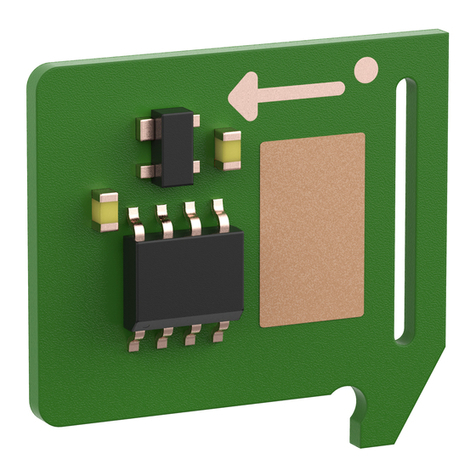
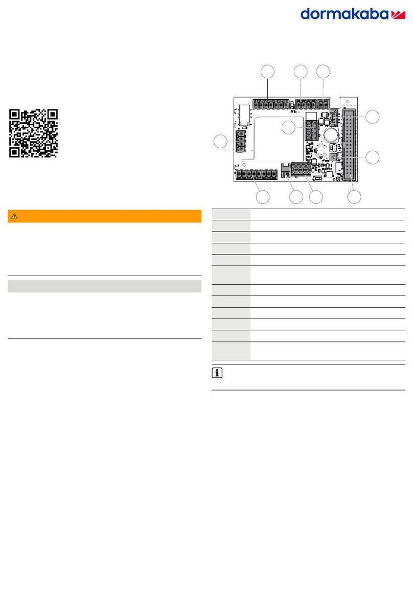
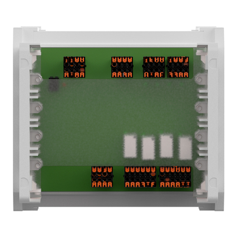
Dormakaba ED connection board CAN User manual

EN
Assembly Instruction
ED connection board CAN
060636 45532/16923 - 2023-04

Table of contents Assembly Instruction
2 ED connection board CAN 060636 45532/16923 - 2023-04
Table of contents
1 Information about this document 3
1.1 Contents and purpose 3
1.2 Target group 3
1.3 Other applicable documents 3
1.4 Abbreviations 3
1.5 Symbols used 3
1.5.1 Hazard category 3
2 Safety 3
3 Product description 4
3.1 Product description 4
3.2 Technical data 4
3.3 Structure of the ED connection board CAN 4
3.4 LED display 5
4 Mounting 6
4.1 Note the structure of the ED 100/250 drive 6
4.2 Mounting the ED connection board CAN 7
5 Connection 10
6 Commissioning 11
7 Troubleshooting 11
7.1 Error display 11
8 Disassembly and disposal 12

Assembly Instruction Information about this document
060636 45532/16923 - 2023-04 ED connection board CAN 3
1 Information about this document
1.1 Contents and purpose
This document describes the mounting and connection of the ED connection
board CAN to an ED100/250 operator.
1.2 Target group
The product may only be mounted and commissioned by a qualified electrician.
1.3 Other applicable documents
• Mounting and commissioning ED 100/250
• Radar sensor M A01 mounting instructions
1.4 Abbreviations
Abbreviation Definition
ED100/250 Electromechanical swing door operators for the
automatic opening and closing of swing doors.
1.5 Symbols used
1.5.1 Hazard category
NOTICE
Means a potentially harmful situation where the product or
something in its environment could be damaged or result in
malfunction.
2 Safety
WARNING
Danger due to failure of protective and safety equipment
The cable routing connects the installed components with each other.
Unprotected cable routing can lead to tampering or malfunctions.
• Lay cables either flush-mounted or
• surface-mount the cables in the steel hose
NOTICE
Material damage due to electrostatic discharge
The component can be damaged by electrostatic discharge!
• Ground your body before touching the component.
• Use ESD safe tool.

Product description Assembly Instruction
4 ED connection board CAN 060636 45532/16923 - 2023-04
3 Product description
3.1 Product description
The ED connection board CAN is a board that is required to make an ED100/250
CAN-capable. It replaces the standard plate in ED and is compatible from
firmware V2.9.000 and up.
3.2 Technical data
Supply
voltage
24 V DC +/- 15 %
Power consumption approx. 20 mA quiescent cur-
rent
Temperature range -15°C to +50°C
Rel. humidity up to 93%, non-condensing
ED protection class IP20
Dimensions Length 88 mm
width 60 mm
height 26 mm
3.3 Structure of the ED connection board CAN
1 2 3
4
5
6
78910
11
Position Layout
1 Locking device
2 Fire protection
3 Emergency stop
4 RS232 interface connection socket
5 Radar sensors M A01 CAN connection cable connection terminals
6 RGB LED function display

Assembly Instruction Product description
060636 45532/16923 - 2023-04 ED connection board CAN 5
Position Layout
7 Ribbon cable connection socket
8 CAN connection cable EntriWorX connection terminals
9 CAN connection cable EntriWorX connection plug
10 Safety sensors
11 Signal inputs for night/bank, impulse outside and impulse inside
The operating conditions specified in the mounting and commissioning instructions
for ED 100/250 operators apply to the ED connection board CAN.
3.4 LED display
The RGB LED function display on the ED connection board CAN is defined as a
secondary function display. The RGB LED function display uses signal colors to
show the current operating status or a fault.
To see the signal colors of the RGB LED function display, remove the ED 100/250
operators’ cladding.
Signal no. Color Description Meaning
1 permanently
red
Self-test error display Self-test error occurred or
CAN device detection is
faulty.
2 Flashing
green
Identification display The device identification is
activated.
3 Flashing yel-
low
CAN device mapping The device assignment is ac-
tive after a CAN reset. De-
vice assignment ends when
the assignment is com-
pleted without errors or
when an error occurs.
4 Flashing red Error display One or more errors are
pending. Error number with
the highest priority is indi-
cated by the number of
flashes.
See “Evaluate errors and rectify faults”.
Signal no. Color Description Meaning
5 Glowing white TMS initialization TMS bus initialization for
sensor and ED connection
board CAN running.
6 Green light: Display operating status
OK
The system is working with-
out errors.

Mounting Assembly Instruction
6 ED connection board CAN 060636 45532/16923 - 2023-04
4 Mounting
4.1 Note the structure of the ED 100/250 drive
1 3 4 5 6
8
7
2
The graphic shows the ED operator for the left door leaf of a 2-leaf door . Further
information on the installation position and settings of the ED operators can be
found in the mounting and commissioning instructions for the ED 100/250.
Position Meaning
1 Power on
2 Standard ED connection board
3 Complete cladding
4 Ribbon cable
5 RJ45 socket (COM 1)
6 User interface with information display
7 Adapter for internal program switch
8 Side cover

Assembly Instruction Mounting
060636 45532/16923 - 2023-04 ED connection board CAN 7
4.2 Mounting the ED connection board CAN
Note Structure of the ED connection board CAN [}3.3].
1. Set the parameter "C1 -> Configuration of the COM1 interface (vertical plug)"
to "1".
2. Switch off the ED operator on the active door leaf (power switch to "0").
3. Remove the cladding (3) from the active door leaf operator, see “Note the
structure of the ED 100/250 drive [}4.1]”.
4. Pull the ribbon cable (4) out of the standard ED connection board (2), see
“Note the structure of the ED 100/250 drive [}4.1]".
5. Remove the plug from the board.
6. Press the locking elements inwards in the suggested order and remove the
standard ED connection board (2), see “Note the structure of the ED 100/250
drive [}4.1]”.
1.
2.
2.
7. Insert the cable ends of the connection cables from the inside to the empty
board slot.
8. Plug the ED connection board CAN over the locking elements.
9. Plug in the plugs and connect the lines.
10. Pull the open cable end of each CAN connection cable out through the middle
opening in the ED connection board CAN.

Mounting Assembly Instruction
8 ED connection board CAN 060636 45532/16923 - 2023-04
11. Connect the CAN connection cable to the connection terminals (5) for the
radar sensor M A01, see also Radar sensor M A01 mounting instructions.
Connect the CAN connection cable to the connection terminal for EntriWorX
(8), see also EntriWorX manual.
Connect the CAN connection cable to the connector plug for EntriWorX (9),
see also EntriWorX manual.
5
89
12. Pull out the open cable ends of all other cables and connect them.
13. Connect all other cables according to the mounting and commissioning
instructions for the ED100/250.
14. Plug the ribbon cable back into the connection socket (7), see "".
15. Insert the serial connection cable into the connection socket (4).
4
16. NOTICE!Guide/stow all cables inside the operator in the cable ducts or
secure with a cable holder to prevent collisions with moving parts!
17. Plug the RJ45 plug of the serial connection cable into the socket (5) next to
the user interface (6), see “Note the structure of the ED 100/250 drive [}4.1]”.

Assembly Instruction Mounting
060636 45532/16923 - 2023-04 ED connection board CAN 9
6
5
4
ðThe ED connection board CAN is connected for commissioning.
18. For 2-leaf units, attach the adapter (6) for internal program switch.
19. Connect the external program switch to the adapter.

Connection Assembly Instruction
10 ED connection board CAN 060636 45532/16923 - 2023-04
5 Connection
35 41 42 3
1631 4 4a
31G63
62
64343
3111317151 13
1 2 3
10
11
Number Assignment
1 43 Locking feedback
3 GND
64 NC
63 NO
62 COM
1G + 24 V switched depending on the smoke detector
3 GND
2 1 + 24V
3 GND
6 Fire protection upgrade card
18k or RM ED
1
3 4 Shutdown drive function
4a GND
10 1 + 24V
15 Signal input safety sensor hinge side
17 Test output
3 GND
1 + 24V
11 Signal input safety sensor opposite side to the hinge
13 Test output
3 GND
11 35 Signal input night/bank
41 Signal input impulse outside
42 Signal input pulse inside
3 GND

Assembly Instruction Commissioning
060636 45532/16923 - 2023-04 ED connection board CAN 11
6 Commissioning
Requirements
The following parameters must be set at the ED user interface:
• The parameter "C1 -> Configuration of the COM1 (vertical plug) interface” is
set to "1".
If the board has previously been used elsewhere, a CAN reset is also required to
"delete" the old CAN participants from the memory (error no. 3).
1. Switch on the ED operator on the active door leaf (power switch to "1").
2. If necessary, trigger the "Cr -> CAN reset" parameter and set the value to "1".
ðAfter approx. 30 secs the LED color changes from white to green.
7 Troubleshooting
7.1 Error display
The error number is indicated by the number of flashes . The message with the
highest priority is displayed.
The LED function display on the ED connection board-CAN indicates the following
error.
Error no. 1
Name TMS communication error
Description The communication between ED control unit and ED con-
nection board CAN is interrupted.
Fix Check the C1 parameter setting on the ED control unit,
check the connection cable between the ED control unit
and the ED connection board CAN. If necessary, actuate
Power on on the ED operator.
Error no. 2
Name CAN initialization error
Description An error occurred when assigning the address for the radar
sensor via the CAN protocol because the expected re-
sponses were not received. This affects the bus communi-
cation with the radar sensor.
Fix Check CAN connection cable and bus termination, i.e. the
DIP switch must be set to ON/"terminating resistor for CAN
active" at position 4. Then operate Power-On on the ED op-
erator and then perform a CAN reset.
Error no. 3
Name Unknown CAN bus participant error
Description Unknown CAN devices were detected during device assign-
ment or the maximum defined number of participants was
exceeded. This affects the bus communication with the
radar sensor.

Disassembly and disposal Assembly Instruction
12 ED connection board CAN 060636 45532/16923 - 2023-04
Fix Check connected devices for correctness and, if neces-
sary, remove them from the bus. Execute CAN reset.
Error no. 4
Name Device assignment error
Description Device positions appear twice in the device assignment.
This affects the bus communication with the radar sensor.
Fix Check the setting of the DIP switches on the radar sensors.
Execute CAN reset.
Error no. 5
Name Missing device error
Description A trained device (radar sensor) is no longer available after
switching on the system. This affects the bus communica-
tion with the radar sensor.
Fix Check CAN connection cables and devices. Actuate Power
on on the ED operator.
Error no. 6
Name CAN communication error
Description The communication between the radar sensor and the ED
connection board CAN is interrupted.
Fix Check the CAN connection cable. If necessary, actuate
Power on on the ED operator.
Error no. 7
Name Radar sensor error
Description A device (radar sensor) sends an emergency message due
to an internal error. This affects the bus communication
with the radar sensor.
Fix Actuate Power on on the ED operator.
8 Disassembly and disposal
Disassembly is carried out in reverse order of the manual.
The product must not be disposed of in domestic waste. Dispose of
the product in an environmentally friendly manner at the collection
points set up for this purpose. Refer to the statutory regulations for
your country.

Assembly Instruction
060636 45532/16923 - 2023-04 ED connection board CAN 13
Notes

Assembly Instruction
14 ED connection board CAN 060636 45532/16923 - 2023-04

Assembly Instruction
060636 45532/16923 - 2023-04 ED connection board CAN 15

www.dormakaba.com
060636 45532/16923 - 2023-04
Copyright © dormakaba 2023
Table of contents
Other Dormakaba Control Unit manuals

Dormakaba
Dormakaba SCU-DR User guide

Dormakaba
Dormakaba MFC User manual

Dormakaba
Dormakaba SIO-DR User manual

Dormakaba
Dormakaba SafeRoute SCU-UP User manual

Dormakaba
Dormakaba MotionIQ ED-CAN User manual

Dormakaba
Dormakaba UNIQUIN User manual

Dormakaba
Dormakaba SLI-A Interlock User manual

Dormakaba
Dormakaba LA GARD 700 Series User manual
Popular Control Unit manuals by other brands

Eaton
Eaton COOPER POWER SERIES manual

Honeywell
Honeywell DirectLine DL421 user manual

Bosch
Bosch Rexroth DB 52 3X E Series operating instructions

NXP Semiconductors
NXP Semiconductors Digital DNA MSC8102 User Guide and Hardware Detailed Design Description

Definox
Definox DCX3 Installation guides

IDEATEC
IDEATEC POLARIS user guide