Dosmatic SuperDos 45 Manual

SUPERDOS 45
Model No.
SuperDos 45 - 0.4%, 2.5%, 5%
Installation & Operating Instructions
Certified ISO 9001:2000 Quality Management System

CONTENTS:
CAUTION:
To reduce risk of injury, user must read and understand the Installation & Operation Instructions
before using this product.
ITEM PAGE
Introduction...........................................................................................................................................3
Safety.....................................................................................................................................................4
Installation..........................................................................................................................................5-7
Operation............................................................................................................................................8-9
Maintenance........................................................................................................................................10
Trouble Shooting.................................................................................................................................11
Repair Parts Motor..............................................................................................................................12
Specifications.......................................................................................................................................13
Repair Parts Lower Ends................................................................................................................14-19
Wear Parts Kits...............................................................................................................................20-22
Warranty.........................................................................................................................................23-24
START UP PROCEDURES
SLOWLY turn on main water pressure until water flows between 5 & 12 gpm (11-45 l/mn) or 30 psi
(2 bar) maximum to fully prime the suction hose.
SLOWLY open the water supply valve and all valves downstream of injector to release entrapped
air. Carefully open inlet valve allowing water to enter and pressurize the injector. Open outlet valve
and close bypass valve. Water will now flow through the injector, and a continuous sound will be
emitted from the injector as water passes through it. Check for system leaks (see page 5) and correct
if necessary. Adjust the outlet valves downstream from the injector, if necessary.
IMPORTANT:
FOR WARRANTY PURPOSES
VISIT OUR
WEBSITE
WWW.DOSMATIC.COM
TO FILL OUT PRODUCT
REGISTRATION FORM!
Part#013827 Rev A

2
QUICK TIPS:
To maintain a long service life for your Dosmatic injector:
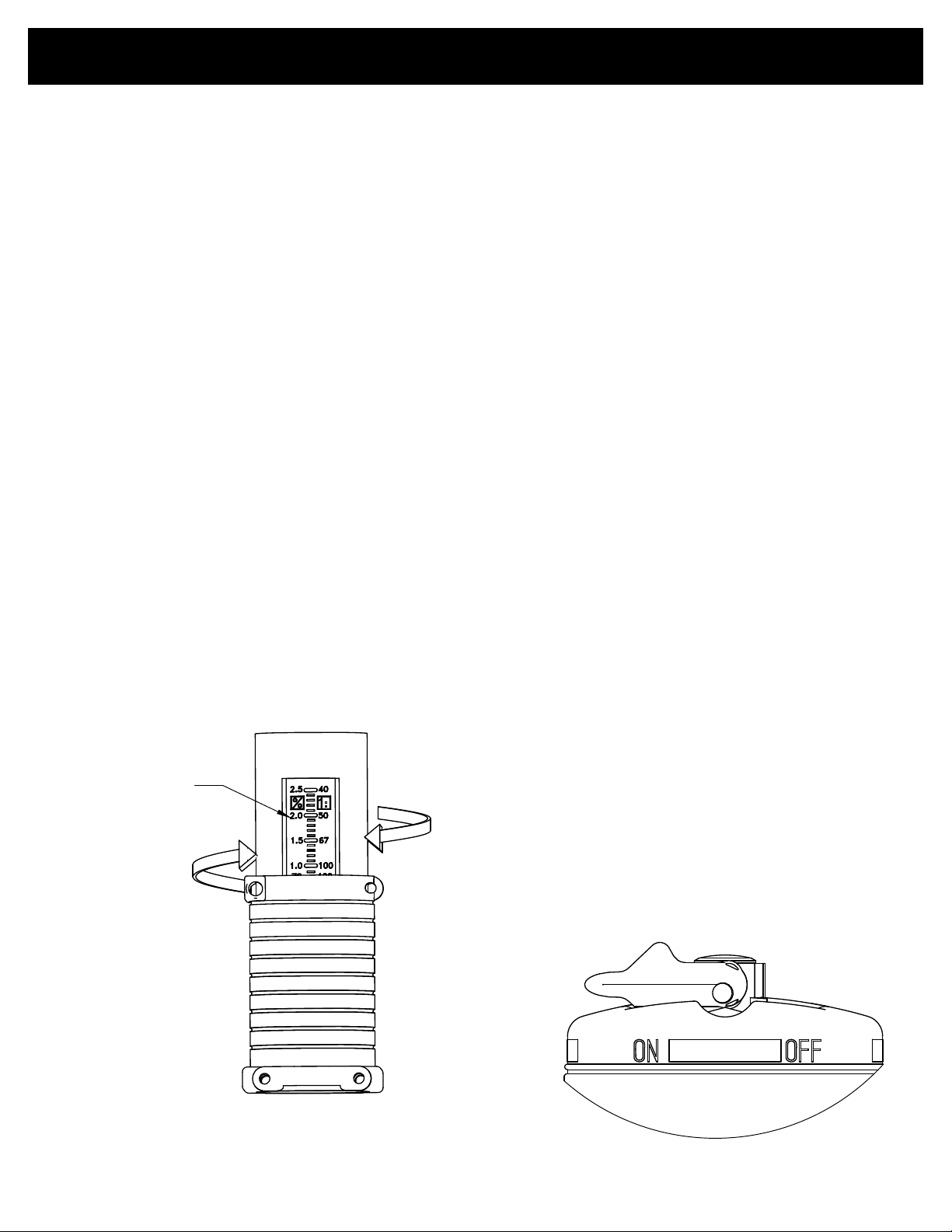
(Part #’s refer to diagrams on following pages)
1. Always cover solution container and keep it clean.
2. Always use clean water.
3. Always filter inlet water.
4. Always keep solution filter (#27 or #60) 2” from bottom of container.
Trouble-shooting your Dosmatic injector:
Injectors should make a clicking sound when in operation. If the unit is not clicking, contact your
authorized Dosmatic repair distributor or return the unit to Dosmatic USA, Inc. If the unit is click-
ing, but is not pulling solution, please inspect the lower end of the injector (see lower end dia-
grams).
Exterior Inspection:
1. Inspect and clean filter (#27 or #60).
2. Inspect the suction tube (#25 or #60) for cracks. Replace if holes exist.
3. If injector still does not pull solution, please proceed to steps 4-7.
Changing the suction tube fitting
4. Remove pin (#79) and carefully pull out the inner cylinder (#7).
5. Unscrew the suction tube fitting (#11) from the inner cylinder (#7).
6. Clean and rinse suction tube fitting assembly (#11). Replace any damaged parts.
7. If injector still does not pull solution, please proceed to steps 8-12.
How to replace wear parts
8. Unscrew the external cylinder (#67), separating it from the body of the injector.
9. Take hold of the shaft (#51) and turn it 90 degrees in any direction to release it. Pull shaft from
its housing.
10. If you have the 0.4% model you must replace the entire shaft assembly. For all other models
remove the dosage piston (#44) by depressing the two “ears” of the shaft (#51) simultaneously and
removing the piston upwards. Remove dosage piston by pulling up. Clean and inspect o-ring (#14).
Replace by sliding a new dosage piston(#44) from top to bottom of the shaft until you hear a click.
The translucent openings (thinner lips) should be on top.
11. Clean, dry and inspect inside the inner cylinder (#7) for scratches or cracks. Replace if needed.

58
56
5%
194309 2.5%
212005
010044
0.4%
194006
194016
194017
0.4% 011015
2.5% 011849M hose kit with filter
0.4% 011026
25
27
44
44
51
17
011812
5% 011849M hose kit with filter
57
INTRODUCTION:
Please take the time to read this instruction manual thoroughly and follow the procedures. This
will help increase the life of your injector.
Certain precautions, which are marked with this symbol need to be read carefully...
The injector is packaged with the following items: (shown in figure 1)
Dosmatic Injector (not shown)
Dosage Piston
O-ring
Manual (not shown)
Mounting Bracket
Mounting nuts and bolts
Filter
Suction Tube
Fig.1
3

SAFETY:
1.SELECT A LOCATION: that is on the water line that chemical injection is desired and meets all
the following requirements as well as all applicable local codes.
Remove Red Caps Prior to Installation.
NOTE: The entire water line down stream from the injector will have chemical injected into it. If
the chemical injected makes the water unsafe to drink label the water lines.
WARNING NOT FOR HUMAN CONSUMPTION!
2. AN APPROVED BACK FLOW PREVENTOR MUST BE INSTALLED: In the water line
ahead of the unit to prevent water and chemical mixture from entering the source water supply.
3. AVOID A POTENTIALLY HAZARDOUS CHEMICAL ACCIDENT: An injector location
should be selected to provide a safe, but accessible, place for the chemical solution container. It
should be kept away from children and/or high usage areas.
4. AVOID SOLUTION CONTAMINATION, use only clean FILTERED water. Do not allow con-
taminants to enter the solution container because they will be pumped into the water line, and can
cause the spread of disease and can also cause excessive wear.
5. WATER TEMPERATURE
Max: 100°F or 38°C
Min: 32°F or 0°C
6. MAX WATER PRESSURE
0.4% -2.5% - 100 PSI/6,9 BAR
5% - 80PSI/5,5 BAR
7. RELEASE WATER PRESSURE: Before working on injector
W
4

1.NOTE: Water going through injector must be free of sand, dirt and grit. Installation of 140 mesh
(104 micron) or finer filter will be required.
2. MOUNT INJECTOR: Securely to a solid object such as a wall. Note arrow on injector indicat-
ing water flow. See fig. 4, pg.8.
3. BACKFLOW PREVENTOR: Install one adequately sized that meets your local code require-
ments.
4. BYPASS VALVE: To bypass injector when not in service or to service injector pipe in the three
valve bypass arrangement as shown in Fig. 4, pg. 8.
5. CHECK SYSTEM FOR LEAKS: Open the bypass valve (A), close valves (B) and (C) so that
the water will not flow into injector SLOWLY turn on the main water line so that water will
run through the plumbing system. Turn on all of the valves located downstream from your injector
to release trapped air. Slowly turn on the inlet valve (B). Open the outlet valve (C) at injector outlet.
Close (A). As water travels freely through your injector, you will hear a soft “clicking” sound.
6. SOLUTION CONTAINER: Refer to figure 4 pg. 8. You may use any size container but we
recommend using one with a lid or cover. To prevent siphoning, place container on a level below
the injector suction tube fitting assembly. To connect your solution container gently push the end of
the suction tube (#25) onto the bottom of the fitting assembly (#11). Place the filter into the solution
container at least 2 inches (5cm) from the bottom. Cover the solution filter with at least 2 inches.
(5cm) of chemical solution.
INSTALLATION:
K
S
:
:
:
:
:
:
:
:
:
:
:
:
:
:
:
:
:
:
:
:
:
:
:
:
:
:
:
:
:
:
:
:
O
r
Turn
o
5

INSTALLATION DRAWINGS:
Fig 1
Current installation
is approx 10 1
2"
266
installed as shown in Fig 1.
Advantage 40 should be currently
Disconnect Advantage 40
Remove 1.5" Union and 194900
as shown in Fig 2.
194900
1.5" Union
Remove
SuperDos 45.
Fig 2
Remove
the extra width of the
194900
Remove
Cut line to accommodate Remove
1.5" Union
The following pages show the necessary steps to convert your set up from our Advantage injectors to the new
SuperDos.
6

INSTALLATION DRAWINGS:
Fig 4
Dimension installation
is approx 13 7
8"
352
1.5" Union
005195
005196
Reducer bushing
005195
1.5" Union
005196
Reducer bushing
Fig 3
at a standard plumbing
supplier
Connect SuperDos unit to 005196
reducer bushing
Connect Reducer bushing to 005195
1.5" union as shown in Fig 3
194900 is replaced by:
005195 (Spears pn 859-015)
005196 (Spears pn 839-212)
Kit to replace these parts is
available from Dosmatic
(pn 011769)
Or parts are available
SuperDos final installation
shown in Fig 4
7

INSTALLATION DRAWINGS:
TYPICAL WALL MOUNTING
Covered Container
Inlet Filter (Required)
Inlet Valve (Required)
Bypass Valve (Required)
Outlet Valve (Required)
Suction Tube
Solution Filter
50 MM
2" Required
(A)
(B) (C)
Fig.4
TYPICAL INSTALLATION
Fig.3
8

OPERATION:
SERVICE FLOW: Water drawn down stream from the injector will automatically cause the injec-
tor to “click” and inject the set amount of solution into the water line. The higher the flow rate the
more frequent the clicking, as the injector is designed to inject solution at the same set ratio regard-
less of water flow.
Water flow and pressure must be within the established specifications. See the specification section
on page 13 for your model.
CHANGE FEED RATE: The feed rate on the injector is adjustable EVEN WHILE OPER-
ATING AND UNDER PRESSURE. Rotate the “Ratio Adjustment Sleeve” (61) to change the
solution injection ratio see fig. 5. The setting indicator mark in the sleeve opening indicates the
approximate ratio of injection setting. Check outlet water for chemical to assure desired feed rate is
being delivered.
NOTE: Do not rotate Ratio Adjuster below lowest setting line on decal. This can cause the injector
to lock.
ON/OFF OPERATION: Injecting solution into the water line can be TEMPORARILY stopped
with the On/Off feature. Moving the “On/Off Lever” to the “OFF” position allows service water to
pass through the injector without injecting chemical. With the On/Off lever set on the “ON” posi-
tion the injector will operate as normal and “clicking” will be heard when water is flowing. It is
recommended to use the three valve bypass in Fig. 4 pg. 8, for continued bypassing or servicing of
the injector.
Example Ratio Adjuster
Setting Indicator
Mark Decrease
(Run Position)
On/Off Lever
Increase
Fig.5
9

MAINTENANCE:
RINSE INJECTOR AFTER EACH USE:
additive allowed to remain in injector can dry out and foul or damage lower end at the next
start up. Put suction tube into a 1 qt. (4 liters) or more container of fresh filtered water. Pull fresh
water through the injector by operating until container is empty. This procedure is not needed for
continuous operation.
BYPASS INJECTOR: When not in use put the injector in bypass mode by using the three valve
bypass (preferred) or the On/Off lever on the injector. See Fig.4 Pg.8.
CLEAN SUCTION TUBE FILTER SCREEN: Inspect each time new solution is added. Clean
as frequently as necessary by washing in fresh water. Remove filter screen (#27) from suction tube
(#25) and run water backwards through it. Replace if necessary. Keep filter screen off bottom of
solution container to prevent dirt and precipitate from contaminating solution.
STORAGE: For extended storage, rinse injector as described above and place entire injector
underwater (in 5 gal container). Monthly, apply a small amount (thimble full) of chlorine bleach to
avoid algae growth.
CLEAN SOLUTION CONTAINER: Keep covered to prevent any contaminants from entering
container. Rinse container thoroughly and often. Do not mix chemicals together that might react
and cause a precipitate. Use FILTERED WATER when filling container.
CLEAN INLET FILTER: Clean or replace inlet filter as required to increase the life of the unit
as well as reduce pressure loss.
REPLACE DOSAGE PISTON AND SHAFT SEAL: The injector is shipped with a spare Dos-
age Piston (44) and shaft seal (17), see Fig. 1, as these are normal wear parts, replace both when
solution injection is less than set amount.
10

TROUBLE SHOOTING:
NO CLICKING SOUND
1. Water flow rate exceeds rated service flow of injector: Reduce flow rate (See Specifications
Pg. 13).
2. Operating pressure exceeds maximum limit: Install a pressure reducer valve (See Specifica-
tions Pg. 13).
3. #17 o-ring if leaking: Replace.
4. Main piston assembly #9 worn: Replace #9 and install a 104 micron filter before injector to
remove abrasive particules from water.
5. Cover #1 or main body #40 bores worn or scored: Lightly sand inside diameter of bores to
remove scoring grooves. Install a 104 micron filter to remove abrasive particles from water.
CLICKING SOUND WITHOUT SUCTION OF SOLUTION
1. Dosage piston #44 and o-ring retainer #15 are installed incorrectly: Be sure #44 dosage pis-
ton is installed thin lips up.
2. Dosage piston #44 worn: Replace as necessary.
3. O-ring seat #14 or dosage piston #44 damaged: Replace as necessary.
4. #7 cylinder is worn or scored: Replace
5. #17 o-ring is worn and/or loose: Replace
6. Suction tube #25 or #60 or suction tube fitting #11 cracked & leaking: Replace as necessary
7. Clogged suction tube filter: Replace and/or clean as necessary.
8. Check valve #13 leaking: Clean & replace as necessary.
WATER RE-FILLING SOLUTION TANK
1. Check valve #13 leaking: Check seat area on suction tube fitting #11. Check valve and seal must
fit loose in the suction tube fitting.
2. Washer seal on #13 is swollen: Replace with new check valve assembly.
11

NOTES:
12

SPECIFICATIONS:
SuperDos 45 - 0.4% 0.50 gpm 45 gpm 0.025% 0.40% 5.0 – 100 psi 1 1/4” npt
1,89 l/mn 170,34 l/mn 1:4000 1:250 0,34 – 6,9 bar 1 1/4” bsp
SuperDos 45 - 2.5% 0.50 gpm 45 gpm 0.20% 2.50% 5.0 – 100 psi 1 1/4” npt
1,89 l/mn 170,34 l/mn 1:500 1:40 0,34 – 6,9 bar 1 1/4” bsp
SuperDos 45 - 5% 0.50 gpm 45 gpm 0.40% 5.00% 5.0 – 80 psi 1 1/4” npt
1,89 l/mn 170,34 l/mn 1:250 1:20 0,34 – 5,5 bar 1 1/4” bsp
Model Flow Rate Feed Ratio Operating
Pressure
Inlet/Outlet
Pipe Connection
Minimum Maximum Minimum Maximum
13

REPAIR PARTS:
194616
194610
194550
3
011172
194605
194612 193641
011869 9
86
34
87
85
1
21
011032 NPT
011032B BSP
40
14
Reference # Part # Description
1 194610 Upper Body
34 193641 Cotter Ring
3 194605 Mixing Chamber Gasket
9 011869 Piston Assembly
21 011172 Shaft Assembly
40 011032 Lower Body NPT 1 1/4"
011032B Lower Body BSP 1 1/4"
85 194612 Upper Shaft Pin
86 194550 Cap
87 194616 On/off handle

LOWER END INJECTOR & WEAR PARTS KITS 0.4%:
Kit A – Wear Parts Kit (dosage piston and o-ring) 011851PV 17, 51
Kit C – Wear Parts Kit (Kit A, inner cylinder and o-ring) 011854PV 17, 51, 63,68
Kit D – Suction Tube Fitting (poppet, o-ring, nut/washer,
spring, fitting
011461V 10, 11, 12, 13, 71, 80
Kit E - Wear Parts (Kits C & D, inner cylinder (2nd inner
cylinder), shaft, pin, gasket)
011835PV 7, 10, 11, 12, 13, 16, 17, 51, 63,
64, 68, 71, 79, 80
Kit F – Lower End Cylinder Kit (inner & outer cylinder,
ratio adjuster, o-rings, retainer clip, pin, gasket)
011960PV 7, 16, 61, 63, 64, 65, 66, 67, 68,
79
Kit H – Motor Piston Assy (upper end kit) 011861 9
Kit M – Mounting Bracket Kit (mounting bracket, 4 hex
caps & nuts)
011432 56, 57, 58
Manual Reference Part # Description of Part
7 194404P Cylinder, inner
10 194418H Spring
11 194412 Fitting, suction tube, 3/8”
12 212120
*Must specify material
O-ring
13 011453A Poppet, check w/washer
15 194004 Seal retainer, o-ring
16 010016
*Must specify material
Gasket, inlet/outlet and cylinder
17 212005
*Must specify material
O-ring
25 011015 Suction tube, 3/8” x 5’
27 011026 Filter and foot valve, suction tube, 3/8” ID
51 011812
*Must specify material
Shaft, Assy with dosage piston
61 194406P Ratio adjustment sleeve
63 212516
*Must specify material
O-ring, inner cylinder (#68)
64 212017
*Must specify material
O-ring, inner cylinder, lower end
65 194310D Pin, upper interlock
66 212025
*Must specify material
O-ring, outer cylinder, lower end
67 011919P Cylinder, outer
68 011458 Cylinder, inner for #7
71 194414 Nut, suction tube fitting
79 194410SS Pin, narrow interlock
80 194415 Twistlock
15

LOWER END INJECTOR PARTS 0.4%:
011015
011026
64
7
16
17
51
66
61
15
194310
010016
011806
194249
194248
194246
011919P
194406
194404
011458
194410
212022
212005
212025
212017
011812
79
67
68
63
25
212516
27
194004
11
194415
194418
194413
194412
194414
194416
011453A13
80
10
12212120
71
65
16

LOWER END INJECTOR & WEAR PARTS KITS 2.5%:
Description of Kit Part # Manual Reference
Kit A – Wear Parts Kit (dosage piston and o-ring) 011850V 17, 44
Kit B – Wear Parts Kit (Kit A, & shaft) 011945V 17, 44, 51
Kit C – Wear Parts Kit (Kit A, inner cylinder and o-ring) 011850CV 7, 17, 44, 64
Kit D – Hose Kit (o-ring, suction tube fitting, check valve, 2
adapters, clamp, hose, filter)
011849M 60
Kit F – Lower End Cylinder Kit (inner & outer cylinder, ratio
adjuster, o-rings, retainer clip, pin, gasket)
011961V 7, 16, 61, 64, 65, 66, 67, 79
Kit H – Motor Piston Assy (upper end kit) 011861 9
Kit M – Mounting Bracket Kit (mounting bracket, 4 hex caps &
nuts)
011432 56, 57, 58
Manual Reference Part # Description of Part
7 194404P Cylinder, inner
14 212005
*Must specify material
O-ring
15 194004 Seal retainer, o-ring
16 010016
*Must specify material
Gasket, inlet/outlet and cylinder
17 212005
*Must specify material
O-ring
44 010044
*Must specify material
Dosage Piston
51 194301F Shaft, with ears
60 011849M Hose braid kit
61 194406P Ratio adjustment sleeve
64 212017
*Must specify material
O-ring, inner cylinder, lower end
65 194310D Pin, upper interlock
66 212025
*Must specify material
O-ring, outer cylinder, lower end
67 194407P Cylinder, outer
79 194410SS Pin, narrow interlock
17

LOWER END INJECTOR PARTS 2.5%:
65
194004
010016
010044
194301
194407P
194406
194404
194410
194310
212005
212005
212025
15
16
44
14
51
67
66
61
64
7
212017
79
17
011849M (kit)60
18

LOWER END INJECTOR & WEAR PARTS KITS 5%:
Description of Kit Part # Manual Refer-
ence
Kit A – Wear Parts Kit (dosage piston and oring) 011852PV 17, 44
Kit B – Wear Parts Kit (Kit A, & shaft) 011950V 17, 44, 51
Kit C – Wear Parts Kit (Kit A, inner cylinder and o-ring) 011856PV 7, 17, 44, 64
Kit D – Hose Kit (oring, suction tube fitting, check valve, 2 adapters, clamp,
hose, filter)
011849M 60
Kit F – Lower End Cylinder Kit (inner & outer cylinder, ratio adjuster, o-rings, retainer
clip, pin, gasket)
011963PV 7, 16, 61, 64,
65, 66, 67, 79
Kit H – Motor Piston Assy (upper end kit) 011861 9
Kit M – Mounting Bracket Kit (mounting bracket, 4 hex caps & nuts) 011432 56, 57, 58
Manual Reference Part # Description of Part
7 194405P Cylinder, inner
14 212005VH o-ring
15 194004 Seal retainer, o-ring
16 010016
*Must specify material
Gasket, inlet/outlet and cylinder
17 212005
*Must specify material
O-ring
44 194309 Dosage Piston
51 194301F Shaft, with ears
61 194406P Ratio adjustment sleeve
64 212017
*Must specify material
O-ring, inner cylinder, lower end
65 194310D Pin, upper interlock
66 212025
*Must specify material
O-ring, outer cylinder, lower end
67 011918P Cylinder, outer
79 194410SS Pin, narrow interlock
60 011849M HOSE BRAID KIT
19
Table of contents
Other Dosmatic Laboratory Equipment manuals
Popular Laboratory Equipment manuals by other brands

Cole Parmer
Cole Parmer Colony Counter 14312-00 user guide

PerkinElmer
PerkinElmer Lambda 365 installation instructions

INWILL LIGHT
INWILL LIGHT XD68 manual

KTI Networks
KTI Networks KPOE-200 installation guide

Waters
Waters Andrew Alliance Shaker+ user manual

Hettich
Hettich ROTINA 420 operating instructions