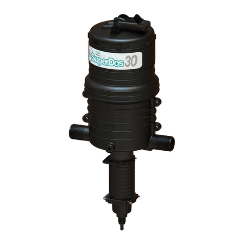
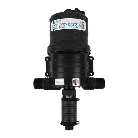
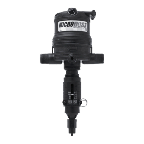
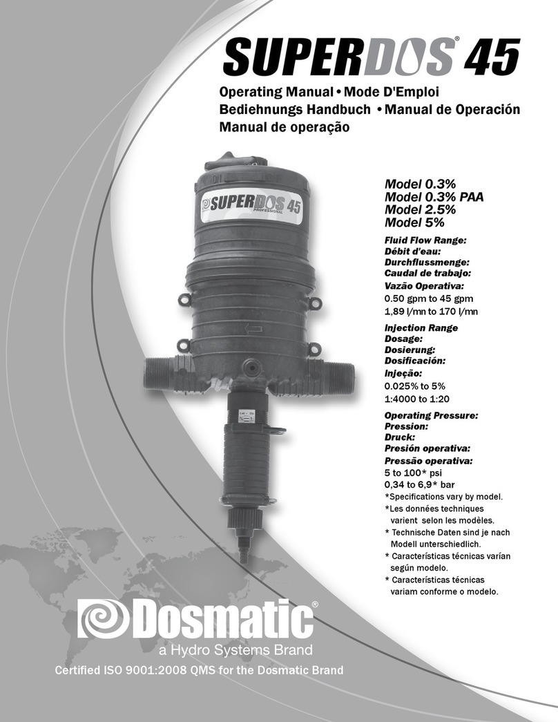
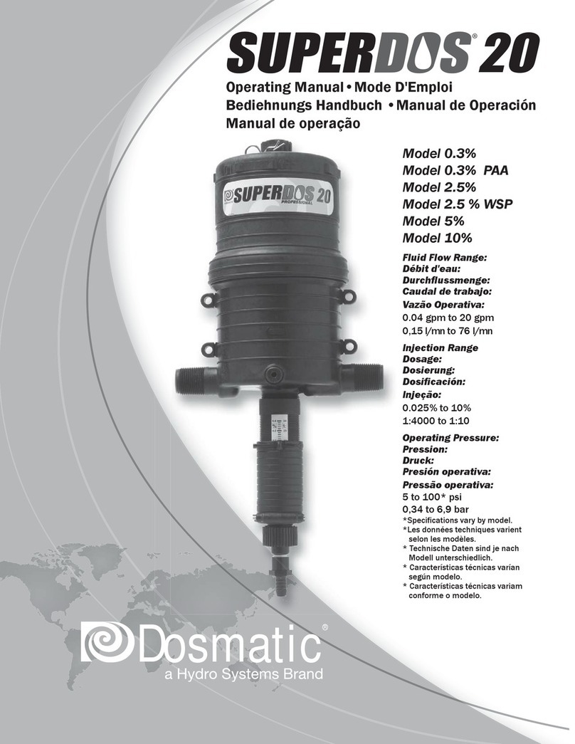
Dosmatic SUPERDOS 20 Manual

SUPERDOS 20
Model No.
SuperDos 20 - 0.4%, 2.5%, 5%, 10%
Installation & Operating Instructions
Certified ISO 9001:2000 Quality Management System

CONTENTS:
CAUTION:
To reduce risk of injury, user must read and understand the Installation & Operation Instructions
before using this product.
ITEM PAGE
Introduction...........................................................................................................................................3
Safety.....................................................................................................................................................4
Installation..........................................................................................................................................5-7
Operation............................................................................................................................................8-9
Maintenance........................................................................................................................................10
Trouble Shooting.................................................................................................................................11
Repair Parts Motor..............................................................................................................................12
Specications.......................................................................................................................................13
Repair Parts Lower Ends................................................................................................................14-19
Wear Parts Kits...............................................................................................................................20-22
Warranty.........................................................................................................................................23-24
START UP PROCEDURES
SLOWLY turn on main water pressure until water ows between 5 & 12 gpm (11-45 lpm) or 30 psi
(2 bar) maximum to fully prime the suction hose.
SLOWLY open the water supply valve and all valves downstream of injector to release entrapped
air. Carefully open inlet velve allowing water to enter and pressurize the injector. Open outlet valve
and close bypass valve. Water will now ow through the injector, and a continuous sound will be
emitted from the injector as water passes through it. check for system leaks (see page 5) and correct
if necessary. Adjust the outlet valves downstream from the injector, if necessary.
IMPORTANT:
FOR WARRANTY PURPOSES
VISIT OUR
WEBSITE
WWW.DOSMATIC.COM
TO FILL OUT PRODUCT
REGISTRATION FORM!
2

57
194006
194016
194017
010044
194309
52
44
44
25
010025
011025
010025
5%
2.5%
4ml
003067
011017
011018
4ml
2.5%
011812
5%
27
17
56
212005 58
INTRODUCTION:
Please take the time to read this instruction manual thoroughly and follow the procedures. This
will help increase the life of your injector.
Certain precautions, which are marked with this symbol need to be read carefully...
The injector is packaged with the following items: (shown in gure 1)
Dosmatic Injector (not shown)
Dosage Piston
O-ring
Manual (not shown)
Mounting Bracket
Mounting clips
Filter
Suction Tube
Fig.1
3

SAFETY:
1.SELECT A LOCATION: that is on the water line that chemical injection is desired and meets all
the following requirements as well as all applicable local codes.
Remove Red Caps Prior to Installation.
NOTE: The entire water line down stream from the injector will have chemical injected into it. If
the chemical injected makes the water unsafe to drink label the water lines.
WARNING NOT FOR HUMAN CONSUMPTION!
2. AN APPROVED BACK FLOW PREVENTOR MUST BE INSTALLED: In the water line
ahead of the unit to prevent water and chemical mixture from entering the source water supply.
3. AVOID A POTENTIALLY HAZARDOUS CHEMICAL ACCIDENT: An injector location
should be selected to provide a safe, but accessible, place for the chemical solution container. It
should be kept away from children and/or high usage areas.
4. AVOID SOLUTION CONTAMINATION, use only clean FILTERED water. Do not allow con-
taminants to enter the solution container because they will be pumped into the water line, and can
cause the spread of disease and can also cause excessive wear.
5. WATER TEMPERATURE
Max: 100°F or 38°C
Min: 32°F or 0°C
6. MAX WATER PRESSURE
10% - 65 PSI/4,5 BAR
1% - 5% - 100 PSI/6,9 BAR
7. RELEASE WATER PRESSURE: Before working on injector
4

1.NOTE: Water going through injector must be free of sand, dirt and grit. Installation of 140 mesh
(104 micron) or ner lter will be required.
2. MOUNT INJECTOR: Securely to a solid object such as a wall. Note arrow on injector indicat-
ing water ow. See g. 3.
3. BACKFLOW PREVENTOR: Install one adequately sized that meets your local code require-
ments.
4. BYPASS VALVE: To bypass injector when not in service or to service injector pipe in the three
valve bypass arrangement as shown in Fig. 4
5. CHECK SYSTEM FOR LEAKS: Open the bypass valve (A), close valves (B) and (C) so that
the water wil not ow into injector SLOWLY turn on the main water line so that water will
run through the plumbing system. Turn on all of the valves located downstream from your injector
to release trapped air. Slowly turn on the inlet valve (B). Open the outlet valve (C) at injector outlet.
Close (A). As water travels freely through your injector, you willhear a soft “clicking” sound.
6. SOLUTION CONTAINER: Refer to gure 4. You may use any size container but we recom-
mend using one with a lid or cover. To connect your solution container gently push the end of the
suction tube (#25) onto the bottom of the tting assembly (#11). Place the lter into the solution
container at least 2 inches (5cm) from the bottom. Cover the solution lter with at least 2 inches.
(5cm) of chemical solution.
INSTALLATION:
5

INSTALLATION DRAWINGS:
TYPICAL WALL MOUNTING
Covered Container
Inlet Filter (Required)
Inlet Valve (Required)
Bypass Valve(Required)
OutletValve (Required)
Suction Tube
Solution Filter
50 MM
2" Required
(A)
(B) (C)
Fig.4
TYPICAL INSTALLATION
Fig.3
6

OPERATION:
SERVICE FLOW: Water drawn down stream from the injector will automatically cause the injec-
tor to “click” and inject the set amount of solution into the water line. The higher the ow rate the
more frequent the clicking, as the injector is designed to inject solution at the same set ratio irre-
gardless of water ow.
Water ow and pressure must be within the established specications. See the specication section
on page 13 for your model.
CHANGE FEED RATE: The feed rate on the injector is adjustable EVEN WHILE OPER-
ATING AND UNDER PRESSURE. Rotate the “Ratio Adjustment Sleeve” (61) to change the
solution injection ratio. See g. 5,. The setting indicator mark in the sleeve opening indicates the
approximate ratio of injection setting. Check outlet water for chemical to assure desired feed rate is
being delivered.
NOTE: Do not screw Ratio Adjuster below lowest setting line on decal. This can cause the injector
to lock.
BYPASS OPERATION: Injecting solution into the water line can be TEMPORARILY stopped
with the optional bypass feature. Moving the “Bypass Lever” to the “OFF” position allows service
water to pass through the injector without injecting chemical. With the bypass lever set on the “ON”
position the injector will operate as normal and “clicking” will be heard when water is owing. It is
recommended to use the three valve bypass valves in Fig. 2, for continued bypassing or servicing of
the injector.
Optional Bypass Lever
Run Position
Setting Indicator
Mark →Decrease
Increase
Fig.5
7

MAINTENANCE:
RINSE INJECTOR AFTER EACH USE:
additive allowed to remain in injector can dry out and foul or damage lower end at the next
start up. Put suction tube into a 1 qt. (4 liters) or more container of fresh ltered water. Pull fresh
water through the injector by operating until container if empty. This procedure is not needed for
continuous operation.
BYPASS INJECTOR: When not in use put the injector in bypass mode by using the three valve
bypass (preferred) or the optional bypass lever on the injector.
CLEAN SUCTION TUBE FILTER SCREEN: Inspect each time new solution is added. Clean
as frequently as necessary by washing in fresh water. Remove lter screen (#27) from suction tube
(#25) and run water backwards through it. Replace if necessary. Keep lter screen off bottom of
solution container to prevent dirt and precipitate from contaminating solution.
STORAGE: For extended storage, rinse injector as described above and place entire injector
underwater (in 5 gal container). Monthly, apply a small amount (thimble full) of chlorine bleach to
avoid algae growth.
CLEAN SOLUTION CONTAINER: Keep covered to prevent dirt, ies, feathers and other y-
ing debris from entering container. rinse container thoroughly and often. Do not mix chemicals
together that might react and cause a precipitate. Use FILTERED WATER when lling container.
CLEAN INLET FILTER: Clean or replace inlet lter as required to increase the life of the unit
as well as reduce pressure loss.
REPLACE DOSAGE PISTON AND SHAFT SEAL: The injector is shipped with a spare Dos-
age Piston (44) and shaft seal (17), see Fig. 1, as these are normal wear parts, replace both when
solution injection is less than set amount.
8

TROUBLE SHOOTING:
NO CLICKING SOUND
1. Water ow rate exceeds rated service ow of injector: Reduce ow rate (See Specications
Pg. 13).
2. Operating pressure exceeds maximum limit: Install a pressure reducer valve (See Specica-
tions Pg. 13).
3. #17 o-ring if leaking: Replace.
4. Main piston assembly #9 worn: Replace #9 and install a 104 micron lter before injector to
remove abrasive particules from water.
5. Cover #1 or main body #40 bores worn or scored: Lightly sand inside diameter of bores to
remove scoring grooves. Install a 104 micron lter to remove abrasive particles from water.
6. Poppets (Upper or Lower) are off poppet arms: Replace all poppet assemblies and reduce
ow and/or pressure.
CLICKING SOUND WITHOUT SUCTION OF SOLUTION
1. Dosage piston #44 and o-ring retainer #15 are installed incorrectly: Be sure #44 dosage
piston is installed thin lips up.
2. Dosage piston #44 worn: Replace as necessary.
3. O-ring seat #14 or dasage piston 344 damaged: Replace as necessary.
4. #7 cylinder is worn or scored: Replace
5. #17 o-ring is worn and/or loose: Replace
6. Suction tube #25 or suction tube tting #11 cracked & leaking: Replace as necessary
7. Clogged suction tube lter: Replace and/or clean as necessary.
8. Check valve #13 leaking: Clean & replace as necessary.
WATER RE-FILLING SOLUTION TANK
1. Check valve #13 leaking: Check seat area on suction tube tting #11. Check valve and seal
must t loose in the suction tube tting.
2. Washer seal on #13 is swollen: Replace with new check valve assembly.
9

SPECIFICATIONS:
SuperDos 20 - 0.4% 0.04 gpm 20 gpm 0.025% 0.40% 5.0 – 100 psi 1” npt
0,15 lpm 75,70 lpm 1:4000 1:250 0,34 – 6,9 bar 1” bsp
SuperDos 20 - 2.5% 0.04 gpm 20 gpm 0.20% 2.50% 5.0 – 100 psi 1” npt
0,15 lpm 75,70 lpm 1:500 1:40 0,34 – 6,9 bar 1” bsp
SuperDos 20 - 5% 0.04 gpm 20 gpm 0.40% 5.00% 5.0 – 100 psi 1” npt
0,15 lpm 75,70 lpm 1:250 1:20 0,34 – 6,9 bar 1” bsp
SuperDos 20 - 10% 0.04 gpm 20 gpm 2.00% 10.00% 5.0 – 100 psi 1” npt
0,15 lpm 75,70 lpm 1:50 1:10 0,34 – 6,9 bar 1” bsp
Model Flow Rate Feed Ratio Operating
Pressure
Inlet/Outlet
Pipe Connection
Minimum Maximum Minimum Maximum
10

REPAIR PARTS:
3
85
011031B BSP
21
194612
194615 (2x)
194550
1
011172
9
193641
194605
86
34
88
011031 NPT
194610
40
011876
011879T 10%
Reference # Part # Description
1 194610 Upper Body
34 193641 Cotter Ring
3 194605 Mixing Chamber Gasket
9 011876 Piston Assembly
011879T Piston Assembly 10%
21 011172 Shaft Assembly
40 011031 Lower Body NPT 1"
011031B Lower Body BSP 1"
85 194612 Upper Shaft Pin
86 194550 Cap
88 194615 Non bypass plug
11

LOWER END INJECTOR & WEAR PARTS KITS 0.4%:
Kit A – Wear Parts Kit (dosage piston/shaft assy, oring) 011851PV 17, 51
Kit C – Wear Parts Kit (Kit A, inner cylinder, oring) 011854PV 17, 51, 68, 81
Kit D – Suction Tube Fitting Assy (poppet, nut, washer,
oring, spring, tting)
011463V 10, 11, 12, 13, 71, 80
Kit E – Wear Parts Kit (Kits C & D, inner cylinder (2nd
inner cylinder), shaft, pin, gasket)
011834PV 7, 10, 11, 12, 13, 16, 17, 51, 64, 68,
71, 80, 81
Kit F – Lower End Cylinder Kit (inner & outer cylinder,
ratio adjuster, oring, retainer clip, pin, gasket)
011960PV 7, 16, 61, 64, 65, 66, 67, 68, 79, 81
Kit G - Lower End Kit, complete (Kit E, outer cylinder,
ratio adjuster, oring, retainer clip, pin, retainer, lter,
solution tube)
011843MV 7, 10, 11, 12, 13, 15, 16, 17, 25, 27,
51, 61, 64, 65, 66, 67, 68, 71, 79, 80,
81
Kit H – Motor Piston Assy (upper end kit) 011863 9
Kit M – Mounting Bracket Kit (mounting bracket, 4 hex
caps & nuts)
011432 56, 57, 58
Manual Reference Part # Description of Part
7 194404P Cylinder, inner
10 194418H Spring
11 194417 Fitting, suction tube, ¼”
12 212120
*Must specify material
O-ring
13 011453A Poppet, check w/washer
15 194004 Seal retainer, o-ring
16 010016
*Must specify material
Gasket, inlet/outlet and cylinder
17 212005
*Must specify material
O-ring
25 010025 Suction tube, ¼” x 5’
27 003067 Filter and foot valve, suction tube, ¼” ID
51 011812
*Must specify material
Shaft, Assy with dosage piston
61 194406P Ratio adjustment sleeve
64 212017
*Must specify material
O-ring, inner cylinder, lower end
65 194310D Pin, upper interlock
66 212025
*Must specify material
O-ring, outer cylinder, lower end
67 011919P Cylinder, outer
68 011458 Cylinder, inner for #7
71 194414 Nut, suction tube tting
79 194410SS Pin, narrow interlock
80 194415 Twistlock
81 212516
*Must specify material
O-ring, inner cylinder (#68)
12

LOWER END INJECTOR PARTS 0.4%:
65
11
194415
194418
194413
194417
194414
194416
011453A13
80
10
12212120
71
194310
010016
011806
194249
194248
194246
011919P
194406
194404
011458
194410
212022
212005
212025
212017
011812
79
67
68
81
25
212516
27
194004
010025
003067
64
7
16
17
51
66
61
15
13

LOWER END INJECTOR & WEAR PARTS KITS 2.5%:
Description of Kit Part # Manual Reference
Kit A – Wear Parts Kit (dosage piston and oring) 011850V 17, 44
Kit B – Wear Parts Kit (Kit A, & shaft) 011945V 17, 44, 51
Kit C – Wear Parts Kit (Kit A, inner cylinder and o-ring) 011850CV 7, 17, 44, 64
Kit D – Suction Tube Fitting Assy (poppet, nut, washer, o-ring,
spring, tting)
011463V 10, 11, 12, 13, 71, 80
Kit E – Wear Parts Kit (Kits C & D, shaft, pin, gasket) 011833PV 7, 10, 11, 12, 13, 16, 17, 44, 51,
64, 71, 80
Kit F – Lower End Cylinder Kit (inner & outer cylinder, ratio
adjuster, o-rings, retainer clip, pin, gasket)
011961V 7, 16, 61, 64, 65, 66, 67, 79
Kit G - Lower End Kit, complete (Kit E, outer cylinder, ratio ad-
juster, o-rings, retainer clips, pins, retainer, lter, solution tube)
011843PV 7, 10, 11, 12, 13, 14, 15, 16, 17,
25, 27, 44, 51, 61, 64, 65, 66,
67, 71, 79, 80
Kit H – Motor Piston Assy (upper end kit) 011863 9
Kit M – Mounting Bracket Kit (mounting bracket, 4 hex caps &
nuts)
011432 56, 57, 58
Manual Reference Part # Description of Part
7 194404P Cylinder, inner
10 194418H Spring
11 194417 Fitting, suction tube, 1/4”
12 212120
*Must specify material
O-ring
13 011453A Poppet, check w/washer
14 212005
*Must specify material
O-ring
15 194004 Seal retainer, o-ring
16 010016
*Must specify material
Gasket, inlet/outlet and cylinder
17 212005
*Must specify material
O-ring
25 010025 Suction tube, ¼” x 5’
27 011017 Filter, for suction tube, ¼” ID
44 010044P Dosage Piston
51 194301F Shaft, with ears
61 194406P Ratio adjustment sleeve
64 212017
*Must specify material
O-ring, inner cylinder, lower end
65 194310D Pin, upper interlock
66 212025
*Must specify material
O-ring, outer cylinder, lower end
67 194407P Cylinder, outer
71 194414 Nut, suction tube tting
79 194410SS Pin, narrow interlock
80 194415 Twistlock
14

LOWER END INJECTOR PARTS 2.5%:
194413
79
212120
194416
194415
194418
194414
194417
010025
011017
61
51
194406
67
194301
194404
212005
212005
66
7
194407P
25
212017
11
212025
010044
010016
194410
194004
011453A 64
14
80
10
13
12
71
65
17
15
16
44
194310
27
15

LOWER END INJECTOR & WEAR PARTS KITS 5%:
Description of Kit Part # Manual Reference
Kit A – Wear Parts Kit (dosage piston and oring) 011852PV 17, 44
Kit B – Wear Parts Kit (Kit A, & shaft) 011950V 17, 44, 51
Kit C – Wear Parts Kit (Kit A, inner cylinder and o-ring) 011856PV 7, 17, 44, 64
Kit D – Suction Tube Fitting Assy (poppet, nut, washer, o-ring, spring, tting) 011462V 10, 11, 12, 13, 71,
77, 80
Kit E – Wear Parts Kit (Kits C & D, shaft, pin, gasket) 011836PV 7, 10, 11, 12, 13, 14,
16, 17, 44, 51, 64,
71, 77, 80
Kit F – Lower End Cylinder Kit (inner & outer cylinder, ratio adjuster, o-rings, retainer
clip, pin, gasket)
011963PV 7, 16, 61, 64, 65, 66,
67, 79
Kit G - Lower End Kit, complete (Kit E, outer cylinder, ratio adjuster, o-rings, retainer
clips, pins, retainer, lter, solution tube)
011846PV 7, 10, 11, 12, 13, 14,
15, 16, 17, 25, 27,
44, 51, 61, 64, 65,
66, 67, 71, 77, 79, 80
Kit H – Motor Piston Assy (upper end kit) 011863 9
Kit M – Mounting Bracket Kit (mounting bracket, 4 hex caps & nuts) 011432 56, 57, 58
Manual Reference Part # Description of Part
7 194405P Cylinder, inner
10 194418H Spring
11 011452 Fitting, suction tube, 1/2”
12 212120
*Must specify material
O-ring
13 011453A Poppet, check w/washer
14 212005
*Must specify material
o-ring
15 194004 Seal retainer, o-ring
16 010016
*Must specify material
Gasket, inlet/outlet and cylinder
17 212005
*Must specify material
O-ring
25 011025 Suction tube, 1/2” x 5’
27 011018 Filter, for suction tube, 1/2” ID
44 194309 Dosage Piston
51 194301F Shaft, with ears
61 194406P Ratio adjustment sleeve
64 212017
*Must specify material
O-ring, inner cylinder, lower end
65 194310D Pin, upper interlock
66 212025
*Must specify material
O-ring, outer cylinder, lower end
67 011918P Cylinder, outer
71 194414 Nut, suction tube tting
77 003039 Hose Barb 1/2” x 3/8”
79 194410SS Pin, narrow interlock
80 194415 Twistlock
16

LOWER END INJECTOR PARTS 5%:
011025
011018
65
194415
194413
194416
011452
194414
194418
212120
80
10
77
003039
79
194310
194004
194309
194301
194406
194405
194410
212005
212005
011918P
212025
011453A
13
12
11
71
17
15
16
44
14
51
67
66
61
64
7
25
212017
27
010016
17

LOWER END INJECTOR & WEAR PARTS KITS 10%:
Description of Kit Part # Manual Reference
Kit B – Wear Parts Kit (Hose Kit) 011849M 60
Kit H – Motor Piston Assy 011879T 9
Kit M – Mounting Bracket Kit (mounting bracket, 4 hex caps & nuts) 011432 56, 57, 58
Manual Reference Part # Description of Part
7 011921P Cylinder, inner
15 194004 Seal retainer, o-ring
17 212005
*Must specify material
O-ring
44 194909 Dosage Piston
51 011908 Shaft, stainless steel
61 194831 Cylinder, outer
66 212402
*Must specify material
O-ring, outer cylinder, lower end
68 212002
*Must specify material
O-ring, cylinder adapter, lower end
72 194830 Adapter
73 194833 Dosage piston guide
93 193003 Capscrew 10-32 x 1/2” SS hex
92 195861 Shaft Cap
79 195911 Ratio Locking Pin
94 212012
*Must specify material
O-ring, outer cylinder
91 212518
*Must specify material
O-ring, dosage piston guide
53 194344 Klipring
95 212007
*Must specify material
O-ring, dosage piston guide
60 011849M Hose kit
18

LOWER END INJECTOR PARTS 10%:
011849M (Kit)60
194342
194343
194344
194832
194004
194833
195861
194831
011921P
193003
194830
212010
011908
212005
212002
194909
212012
212402
51
53
17
15
68
72
44
73
91
92
93
94
7
66
61
212518
011879T piston assy)
(#51 is part of the
195911
21200795
79
19

WARRANTY:
The Dosmatic Warranty
We believe that we make the best and most reliable water-driven injectors available. Therefore, our war-
ranty reects our condence; we will back our units with the best guarantee available.
1. Dosmatic will provide for replacement of all parts proven to be defective in material or workmanship
from the date of purchase for the following time periods:
In the United States and Canada All Other
3 years – The cover and body 1 year – Cover, body, motor piston, lower end*
2 years – The motor piston
1 year – The lower end*
*NOTE: (Your only responsibility is ordinary maintenance – ltering incoming water and solution and
replacing the o-ring and dosage piston when worn)
2. Return the unit to the distributor or to Dosmatic’s manufacturing facility, freight prepaid. Upon inspec-
tion, if found to be defective in material or workmanship, the unit will be repaired or replaced, at Dosmat-
ic’s option, free of charge, and will be returned freight prepaid.
3. This warranty is invalid if the defects are found to be due to the product’s misuse, lack of maintenance,
defective installation, freezing, water hammer, misuse or abuse or unwanted side effects due to the chemi-
cals you choose to inject. The dosage piston, seals and o-rings are not covered under warranty nor is dam-
age caused by water impurities, including but not limited to, sand or iron. A lter no coarser than 140
mesh or 104 micron must be used in front of the unit for the warranty to be valid. Dosmatic will not be
responsible if the unit is used under conditions outside of its operating tolerances listed in this manual.
4. Dosmatic shall not be liable for incidental or consequential damage, such as any economic loss, result-
ing from breach of this written warranty or any implied warranty.
5. To return a unit for repair:
1. Thoroughly rinse all chemical solution from the lower end of the unit.
2. Drain the water from the upper end of the injector, leaving a small amount so that the seals do not dry
out.
3. If possible, identify the chemical solution injected and include a copy of the chemical manufacturer’s
Material Safety Data Sheet for each chemical injected.
4. All claims for warranty repair must include a copy of the original invoice listing the serial number of the
injector to be repaired.
5. With each injector returned, please ll out the return form in this manual.
6. If returning to Dosmatic, ship to:
Dosmatic U.S.A.
1230 Crowley Circle
Carrollton, TX 75006
7. For the name of your nearest Service Center, call us toll free at (800) 344-6767 or at
(972) 245-9765.
6. There are no warranties which extend beyond those described above.
20
This manual suits for next models
4
Table of contents
Other Dosmatic Laboratory Equipment manuals
Popular Laboratory Equipment manuals by other brands

Essilor
Essilor Pro-B 300 user manual

Molecular Devices
Molecular Devices Sofnolime HiCap CO2 user manual

lbx
lbx HDB120 Series user manual

Daihan Scientific
Daihan Scientific Eva-05 user manual

Spinner II
Spinner II 600 HD installation instructions

Markes International
Markes International HiSorb Agitator Instructions for use