manuals.online logo
Brands
  1. Home
  2. •
  3. Brands
  4. •
  5. DOTECH
  6. •
  7. Temperature Controllers
  8. •
  9. DOTECH TX3 Series User manual

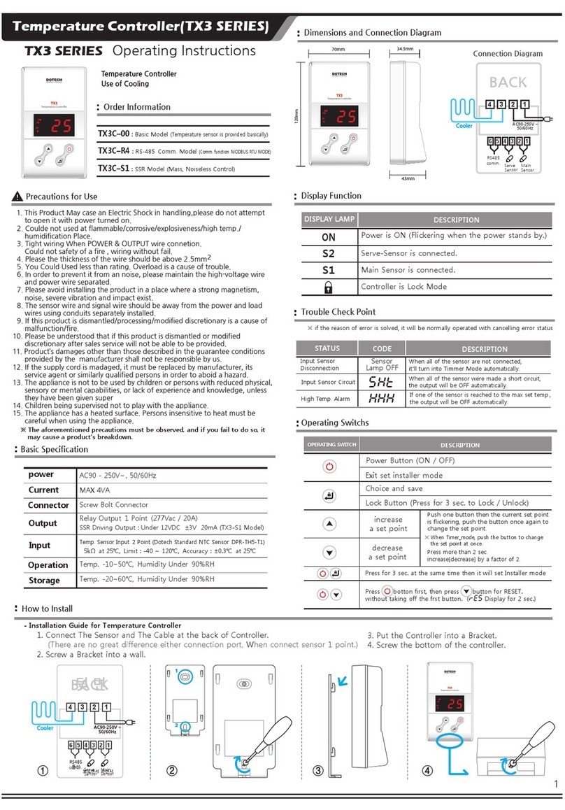
DOTECH TX3 Series User manual

TX3 SERIES
ON
S2
S1
SHT
HHH
TemperatureController
TX3
ON
S2
S1
1
TemperatureController
TX3
ON
S2
S1
70mm
120mm
TemperatureController
TX3
34.5mm
43mm
ON
S2
S1
AC90-250V ~
50/60Hz
6 5 4 3 2 1
4 3 2 1
1
2
④③②①
AC90-250V ~
50/60Hz
6 5 4 3 2 1
4 3 2 1
Cooler
Heater
Cooler
Heater
Precautions for Use
Temperature Controller(TX3 SERIES)
Basic Specification
Order Information
TX3–00
: Basic Model
(Temperature sensor is provided basically)
TX3–R4
: RS-485 Comm. Model
(Comm. function MODBUS RTU MODE)
TX3–S1
: SSR Model (Mass, Noiseless Control)
Output
Input 5kΩ at 25℃, Limit : -40 ~ 120℃, Accuracy : ±0.3℃ at 25℃
Connector
Dimensions and Connection Diagram
How to Install
Display Function
Temperature Controller is multi-functional thermometer
for both cooling and heating to control temperature in
construction site, fashion, factories, offices, etc.
Operation
Storage
SSR Driving Output : Under 12VDC ±3V 20mA (TX3-S1 Model)
DISPLAY LAMP DESCRIPTION
Power is ON (Flickering when the power stands by.)
Main Sensor is connected.
Serve-Sensor is connected.
Controller is Lock Mode
※ The aforementioned precautions must be observed, and if you fail to do so, it
may cause a product’s breakdown.
Trouble Check Point
STATUS DESCRIPTION
When all of the sensor are not connected,
it’ll turn into Timmer Mode automatically.
Input Sensor
Disconnection
Input Sensor Circuit
High Temp. Alarm
※ if the reason of error is solved, it will be normally operated with cancelling error status
CODE
Sensor
Lamp OFF
When all of the sensor were made a short circuit,
the output will be OFF automatically.
If one of the sensor is reached to the max set temp.,
the output will be OFF automatically.
Connection Diagram
Serve
Sensor
RS485
comm. Main
Sensor
- Installation Guide for Temperature Controller
1. Connect The Sensor and The Cable at the back of Controller.
(There are no great difference either connection port, When connect sensor 1 point.)
2. Screw a Bracket into a wall.
1. This Product May case an Electric Shock in handling,please do not attempt
to open it with power turned on.
2. Coulde not used at flammable/corrosive/explosiveness/high temp./
humidification Place.
3. Tight wiring When POWER & OUTPUT wire connetion.
Could not safety of a fire , wiring without fail.
4. Please the thickness of the wire should be above 2.5mm
2
5. You Could Used less than rating. Overload is a cause of trouble.
6. In order to prevent it from an noise, please maintain the high-voltage wire
and power wire separated.
7. Please avoid installing the product in a place where a strong magnetism,
noise, severe vibration and impact exist.
8. The sensor wire and signal wire should be away from the power and load
wires using conduits separately installed.
9. If this product is dismantled/processing/modified discretionary is a cause of
malfunction/fire.
10. Please be understood that if this product is dismantled or modified
discretionary after sales service will not be able to be provided.
11. Product’s damages other than those described in the guarantee conditions
provided by the manufacturer shall not be responsible by us.
12. If the supply cord is madaged, it must be replaced by manufacturer, its
service agent or similarly qualified persons in order to aboid a hazard.
13. The appliance is not to be used by children or persons with reduced physical,
sensory or mental capabilities, or lack of experience and knowledge, unless
they have been given super
14. Children being supervised not to play with the appliance.
15. The appliance has a heated surface. Persons insensitive to heat must be
careful when using the appliance.
Operating Instructions
Temp. -10~50℃, Humidity Under 90%RH
Temp. -20~60℃, Humidity Under 90%RH
Temp. Sensor Input 2 Point (Dotech Standard NTC Sensor DPR-TH5-T1)
Relay Output 1 Point (277Vac / 20A)
Screw Bolt Connector
MAX 4VA
AC90 - 250V~ , 50/60Hz
power
Current
Operating Switchs
OPERATING SWITCH DESCRIPTION
Power Button (ON / OFF)
Choice and save
Lock Button (Press for 3 sec. to Lock / Unlock)
increase
a set point
decrease
a set point
Push one button then the current set point
is flickering, push the button once again to
change the set point.
Press for 3 sec. at the same time then it will set Installer mode
Exit set installer mode
※ When Timer_mode,
push the button to change
the set point at once.
Press more than 2 sec.
increase[decrease] by a factor of 2.
3. Put the Controller into a Bracket.
4. Screw the bottom of the controller.
BACK
BACK
Press botton first, then press button for RESET.
without taking off the frst button. (RES Display for 2 sec.)
Serve
Sensor
Main
Sensor
RS485
comm.
2
-4-
-5-
2 4.6
2 4.5
DIF
RT
UH
UL
HH
COR
PED
OUT
H
ID
BPS
2.0
I 0
3
0.0
6 0
- I 0
50
-5-
FNO
HNO
I
96
I
I
OFF(0)
OFF(0)
120
-1256
48 : 4800bps 96 : 9600bps
I92 : 19200bps 384 : 38400bps
600 : 600bps
℃
Sec
℃
℃
Sec
Sec
Min
-
1
0
20
999
1
1
1
1
1
1
1
1
-1919
-9-
60
-40
1
-199
1
-099
1
001
002
003
004
005
006
007
008
018
019
017
016
※
※
※
※
※
※
※
※
009
010
011
012
TYP
DP
999
Min
Min
1
1
OFF(0)
OFF(0)
DFT
DFP
0. I
H
OFF
OFF
999
0.1:
0.1
1:
1
Heater / Cooler ON
Heater / Cooler OFF
ON OFF
30
29
28
ON
OFF OFF
-5
-6
-7
ON
OFF OFF
8.0
7.0
6.0
5.0
OFF
OUT1 OUT1 OFF
How to set by user
※ If there’s no input made for 3 seconds during the setting, then
it returns back to the Present Temperature Mode automatically.
Press ▲ key or ▼ key
Display Present Temperature
How to set by installer
- How to set the set temperature
Press ▲ key or ▼ key
Display Present Time level
Timmer Control
- How to set the set Operational Level
※ Display changed operational ratio
Sensor Control
How to control
- How to operate in Sensor Control Mode
SET : 30 ℃
DIF : 2℃
Tem p . Tem p .
TimeTime
Heater ON at 28℃,
Heater OFF at 30℃
SET : -7 ℃
DIF : 2℃
Cooler ON at -5℃,
Cooler OFF at -7℃
● 2 Sensors
● 1 Sensors
Current Temp. is operated 70% of main sensor and 30% of serve-sensor.
Current Temp. Control is using the input of the connected sensor.
- How to operate in Timmer Mode
A Period(PED) - 10(min),
Level(OUT) - -6-
Control the Heater repeatedly according to Period and the Level.
● Timmer mode
operating time
ON Time : A Period(1~60min) * (level(0~9) * 6sec)
OFF Time : A Period(1~60min) - ON Time
It is controlled heater/cooler by compare Current temp. with Set temp.
10 Minutes
6 Minutes
PV
PV
- How to change the set group when The Sensor is connected
NO. CODE DESCRIPTION DESCRIPTION UNIT STEP MIN. MAX.
DEFAULT
HOW TO
CHANGE
Control Deviation
Min. OFF Time
Set Value Max.
Set Value Min.
Over High Temp. Alarm
Sensor Correction
Operational Period
Operational Level
Communication Address
(TX3H-R4)
Communication Speed
(TX3H-R4)
Communication
Floor Number (TX3H-R4)
Communication
Hall Number (TX3H-R4)
Set control sensitivity of control output. Setting Range -19 ~ 19℃
No output within Min, OFF time after control output OFF.
Set a minimum value of the set temperature available to be set by user.
Set a maximum value of the set temperature available to be set by user.
Correct the accuracy of the temp. sensor.
e.g) If displayed temp. is 19℃ and I/O temp. is 18℃ , it is corrected by in putting -1℃
No output, when the temp. reach the set point Set
Input ON/OFF cycle of output.
e.g) If PED is 20 Min. and OUT is -1-, the output at sensor error is OFF for 18 Min. & ON for 2 Min.
Input ON/OFF level of output.
Set communication address.. (MODBUS Protocol)
※ If FOT ‘0’ , only display
Set communication speed. (MODBUS Protocol)
※ If FOT ‘0’ , only display (If RCU128 mode, Fixed 600bps)
Set communication Floor Number. (Communication RCU128)
※ If ‘0’, MODBUS Mode
Set communication Hall Numbe. (Communication RCU128)
※ If FOT ‘0’ , not display
Push one
button then
the current set
point is
flickering,
push the
button once
again to
change the
set point.
DOTECH,INC l http://www.dotech21.com
[email protected]
6F, JOONGANG-ILBO 778 Wonsi-Dong, Danwon-Gu, Ansan-Si,
Gyeonggi-Do, Korea TEL : +82-31-495-3767 / FAX : +82-31-495-3917
● The set temperature is indicated by flickering at every
0.5 seconds intervals, and this set temperature can be
extablished by using the ▲key or ▼key.
● The set temperature is indicated by flickering at every
0.5 seconds intervals, and this set temperature can be
extablished by using the ▲key or ▼key.
DIF
1.
Press for 3 sec. at the same time then it will display code 001.
3. After all setting, Setting group is over & return Running mode by Press button.
2. After setting , Save or go to next code by Press button
RES
※. How to reset : Press button first, then press button for Reset. without taking off the first button. Display for 2 sec.
※ If The Sensor is disconnected, Set group is NO.(007-019).
Control Output is OFF during defrost time.
- Defrost function
e.g ) Set Temp. : 5.0℃
D I F : 2.0℃
D F P : 240 min
D F T : 15 min
temp.
time
defrost
240min 15min 240min 15min
defrost
Defrost Cycle
Defrost Time
Type Select
Decimal Point Display
Set defrost time
Set between defrost intervals
Set control function of control output.
(No use output function(Only display), Cooling , Heating)
Select temp display method.
Display 1st decimal place. or No display decimal points.
OFF
: Display
CH
: Cooling : Heating

This manual suits for next models

3

Other DOTECH Temperature Controllers manuals

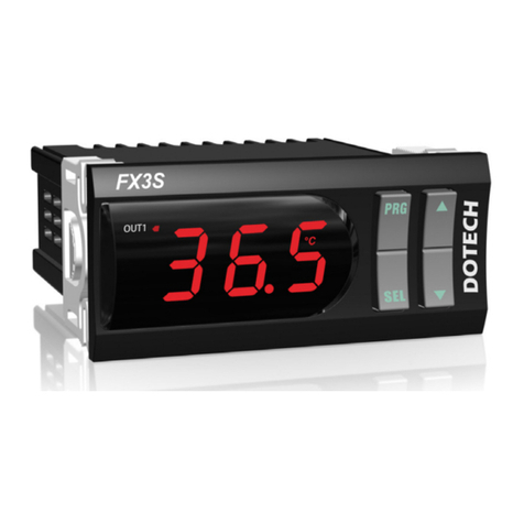
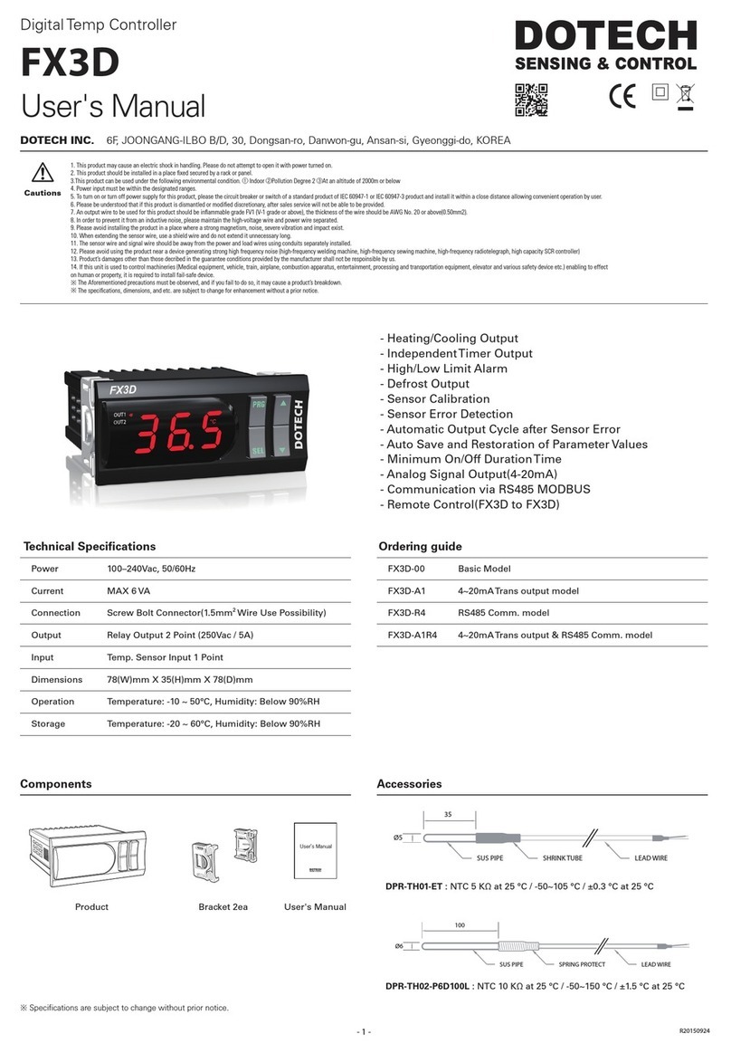
DOTECH FX3D User manual

DOTECH

DOTECH FX3D User manual

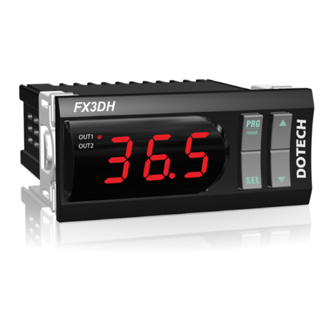
DOTECH FX3DH User manual

DOTECH

DOTECH FX3DH User manual

DOTECH HTX32C User manual

DOTECH

DOTECH HTX32C User manual

DOTECH TX3 Series User manual

DOTECH

DOTECH TX3 Series User manual

DOTECH FX3S User manual

DOTECH

DOTECH FX3S User manual

Popular Temperature Controllers manuals by other brands

THORLABS ITC8000 Operation manual

THORLABS

THORLABS ITC8000 Operation manual

Cumberland Integra EXPERT 64EU user manual

Cumberland

Cumberland Integra EXPERT 64EU user manual

Kathrein ESO 005 Guide

Kathrein

Kathrein ESO 005 Guide

Autonics TK4N instruction manual

Autonics

Autonics TK4N instruction manual

Autonics TK Series user manual

Autonics

Autonics TK Series user manual

Emerson R-410A Specifications

Emerson

Emerson R-410A Specifications

PCS VC-MP instruction manual

PCS

PCS VC-MP instruction manual

Shini STMC-W manual

Shini

Shini STMC-W manual

Trane PolyTherm ARTC-SVX005A-EN Installation, operation and maintenance

Trane

Trane PolyTherm ARTC-SVX005A-EN Installation, operation and maintenance

Bryant Preferred owner's manual

Bryant

Bryant Preferred owner's manual

GIC PR-69 Series instructions

GIC

GIC PR-69 Series instructions

THORLABS MTD415T datasheet

THORLABS

THORLABS MTD415T datasheet

HTW ECO-THERMAL owner's manual

HTW

HTW ECO-THERMAL owner's manual

Full Gauge TO-712B quick start guide

Full Gauge

Full Gauge TO-712B quick start guide

Vector TCY-FT2-U manual

Vector

Vector TCY-FT2-U manual

Heat Controller B-VCH12FC-1 owner's manual

Heat Controller

Heat Controller B-VCH12FC-1 owner's manual

resideo ADEMCO TS300 Installation and operating instructions

resideo

resideo ADEMCO TS300 Installation and operating instructions

Minco CT425 Technical user guide

Minco

Minco CT425 Technical user guide

manuals.online logo
manuals.online logoBrands
  • About & Mission
  • Contact us
  • Privacy Policy
  • Terms and Conditions

Copyright 2025 Manuals.Online. All Rights Reserved.