DPA 4003 User manual

Omnidirectional
Microphones
Type 4003
Type 4006
User’s Manual

Omnidirectional Microphones
Type 4003, Type 4006
Technical Description . . . . . . . . . . . . . . . . . . . . . . . Page 2
Full Specifications . . . . . . . . . . . . . . . . . . . . . . . . . . Page 6
Care of Microphones . . . . . . . . . . . . . . . . . . . . . . . Page 14
Service and Repair . . . . . . . . . . . . . . . . . . . . . . . . . Page 16
Warranty . . . . . . . . . . . . . . . . . . . . . . . . . . . . . . . . . Page 16
CE Standard . . . . . . . . . . . . . . . . . . . . . . . . . . . . . . . Page 16
Contents
User’s Manual

The cartridge
Types 4003 and 4006 are omnidirectional (pressure) microphones which use
a 16mm diameter prepolarized condenser cartridge. The diaphragm is a nickel
foil which has been coated with an ultra-thin polymer layer for optimum
corrosion resistance. The microphone housing is of German silver, an alloy
with a high content of nickel to match the stable thermal qualities of the
diaphragm. The cartridge has low self noise (typical 15dB(A) re. 20µPa) and
high sensitivity (4003: 45mV/Pa and 4006: 10mV/Pa). For optimum stability
the microphone cartridges have undergone a special pre-aging process which
releases all tensions in the materials and stabilizes the polarization voltage.
The preamplifier
Types 4003 and 4006 are acoustically identical, but differ in their preamplifier
powering system. The 4003 is powered with 130V via the HMA4000 High-
Voltage Microphone Amplifier and has a modified 4-pin XLR-connector (see
Fig. 1 for pin designation). This special powering system enables the micro-
phone preamplifier to handle approximately 10dB higher SPL than similar
microphone types powered through conventional P48 systems (4003: 154dB
SPL peak and 4006: 143dB SPL peak). Furthermore the 4003 together with the
HMA4000 is a totally transformerless system and therefore has an extended
low-frequency handling capability (10Hz to 20kHz ± 2dB). The 4006 is powered
via a standard P48 system and is equipped with a standard 3-pin XLR-connector
(see Fig. 2 for pin designation). Types 4003 and 4006 use state of the art
low-noise preamplifier technology. The preamplifiers are driven with unity
gain to keep noise as low as possible.
2
Technical Description
User’s Manual

All microphones come with an individual calibration chart with the
specifications of self noise, sensitivity and the frequency response.
3
Technical Description
User’s Manual
Important: The microphones will only live up to their specifications if
powered correctly.
Fig. 1. External view of the output socket of the Type 4003.
Fig. 2. External view of the output socket of the Type 4006.

The Nearfield Grid
The Nearfield Grid DD0251 on the microphone cartridge is designed to have
a linear on-axis frequency response for near field applications (see Fig. 3 for
frequency responses measured with the Nearfield Grid). The grid can be
exchanged with the DD0297 Diffusefield Grid or the UA0777 Nose Cone.
The Diffusefield Grid
The Diffusefield Grid DD0297 is supplied as standard. It is designed for diffuse-
field recordings, or recordings in the far field. The grid gives a high-frequency
boost on-axis of 6dB around 15kHz (see Fig. 4) without adding noise to the
recording. This boost gives a linear diffuse-field (far field) response up to 15kHz.
The Nose Cone
The Nose Cone UA0777 is available as an optional accessory . As with the
Diffusefield Grid DD0297, the Nose Cone is simply screwed onto the micro-
phone cartridge in place of the Nearfield Grid DD0251. When fitted, the
Nose Cone gives the microphone a true omnidirectional response even at
high frequencies (see Fig. 7) and a linear diffuse-field response (see Fig. 5).
These qualities are useful at any distance for an even tonal balance of sound
arriving at all angles of incidence, e.g. room reverberation or several sound
sources placed around the microphone. The diaphragm is placed in a slot
behind the solid cone and sound waves only have access to the diaphragm
through the side of the Nose Cone. This way the Nose Cone prevents an
on-axis, high frequency sound pressure build-up on the microphone, which
is the reason for normal flat fronted omnidirectional microphones becoming
more and more directional for higher frequencies. There is however, a slight
high frequency boost on axis.
4
Technical Description
User’s Manual

Acoustic Pressure Equalizers
Available as optional acoustical attachments are also the APE’s – Acoustic
Pressure Equalizers. The APE’s use diffraction to passively modify the sound
field near the microphone diaphragm, thus changing the microphone’s
frequency response and, in particular, the polar response (see Fig. 11 and Fig.
12) without adding any electrical noise to the recording. The size and shape
of the APE determines the acoustical changes of the microphone. The APE’s
are precision made from a special compact nylon material and will only fit
the Types 4003 and 4006 fitted with the standard Nearfield Grid DD0251.
There are four different APE’s in the range: L30B is a Ø30mm ball-shaped
APE marked with a blue dot, L40B is a Ø40mm ball-shaped APE marked with
a green dot, L50B is a Ø50 mm ball-shaped APE marked with a red dot and
the L110C is a cylinder-shaped APE, 110mm long and marked with a yellow
dot. The APE’s can be obtained as single units or in two different equalizer
kits: APE L4 contains 4 different APE’s and APE L8 contains 2x4 different
APE’s. See Fig. 14 for how to mount the APE’s on the microphones.
The Passive Connection Converter
The PCC4000 Passive Connection Converter is an optional accessory that
makes it possible to run High-Voltage Microphones on standard 48 V
phantom power with reduced microphone specs. The maximum reduction of
the microphone SPL handling capability will be 13dB and it is possible to
drive up to 100m of cable with the PCC4000 with the same specifications.
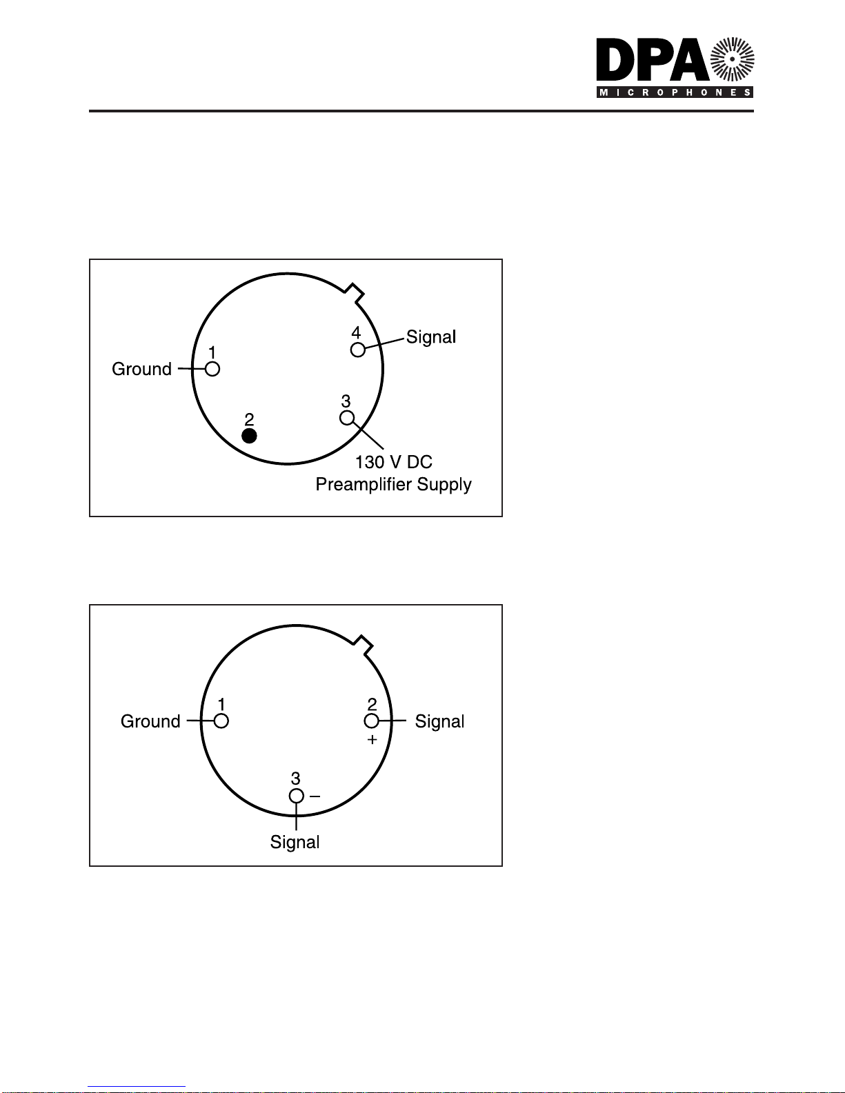
Like the High-Voltage Microphones the PCC4000 is transformerless. The
input connector is a modified 4-pin female XLR for connection directly to
the microphone. The output is a standard 3-pin male XLR-connector for
connection to standard cables.
5
Technical Description
User’s Manual

Cartridge type:
Pre-polarized condenser B&K Type MM0042
Principle of operation:
Pressure
Power Supply:
4003:HMA4000 Two-channel High-Voltage Microphone
Amplifier - 130V or PCC4000 Passive Connection
Converter for P48
4006:Phantom P48
Frequency range:
4003: On-axis: 10Hz - 20kHz ±2dB
4006: On-axis: 20Hz - 20kHz ±2dB up to 124dB peak
Phase response:
See Fig. 8 and 9. Phase matching between any two
microphones: ±10°
Directional characteristics:
Omnidirectional
Sensitivity:
4003: Nominally 40mV/Pa; -27dB re. 1V/Pa unloaded (at 250Hz)
4006: Nominally 10mV/Pa; -40dB re. 1V/Pa unloaded (at 250Hz)
Equivalent noise level A-weighted:
Typ. 15dB(A) re. 20µPa (max. 17dB(A))
Equivalent noise level CCIR 468-1:
Typ. 27dB (max. 29dB)
Max SPL:
4003: 154dB SPL peak (f< 4kHz)
4003: 151dB SPL peak (f< 14kHz)
4006: 143dB SPL peak (f > 200Hz)
Total Harmonic Distortion:
129 dB SPL peak (<0.5% THD)
135 dB SPL peak (<1% THD)
Preamplifier:
Frequency range:
4003: 20Hz to 50kHz ±0,2dB, 5Hz to 150kHz -3dB
4006: 20Hz to 40kHz ±1dB
Output impedance:
<75 Ohm
Cable drive capability:
4003: With HMA4000: Up to 300m
4003: With PCC4000: <100m
4006: Up to 300m
6
Full Specification
User’s Manual

Polarity:
4003:Positively increasing sound pressure produces positive-going
voltage at pin 4. Pin 1: Ground, Pin 2: Not used, Pin 3: 130 V DC
preamplifier supply, Pin 4: Signal. See Fig. 1.
4006:Positively increasing sound pressure produces positive-going
voltage at pin 2. Pin 1: Ground, Pin 2: Signal +, Pin 3: Signal return.
See Fig. 2
Difference frequency distortion:
(DF2, DF3, Df = 80Hz) <1% at 135dB SPL peak
Temperature coefficient:
-0,025dB/°C at 25°C, 1013 hPa, 250Hz
Static pressure coefficient:
-0,002dB/hPa at 25°C, 1013 hPa, 250Hz
Influence of vibration:
64dB equivalent SPL for 1m/s2 in direction of
greatest sensitivity
Influence of magnetic field:
45dB equivalent SPL for 80A/m, 50Hz in direction
of greatest sensitivity
Operating temperature range:
-10 to +70°C (+14 to 158°F)
Dimensions:
Microphone length:
165mm
Microphone diameter:
19mm
Capsule diameter:
16mm
Weight:
150g
For use with Microphone Amplifier:
HMA4000 Hi-Voltage Microphone Amplifier, 2 ch.
Accessories Included
Microphone Holders & Suspension Mounts
UA0639 Microphone Clip
Acoustic Modification Accessories
DD0251 Nearfield Grid, Silver
DD0297 Diffusefield Grid, Black
Windscreens
UA0638 Windscreen for Ø16mm Microphone
7
Full Specification
User’s Manual

8
Full Specification
User’s Manual
Fig. 3. On-axis and diffuse-field responses of Types 4003 and 4006 with the Nearfield
Grid DD0251 fitted.
Accessories Available
Shock Mounts
RSM4000 Shock Mount for
Windjammer
UA0897 Shock Mount
Shock Mount Rubbers
DDS0731 Rubber Mount 19mm,
Medium Soft
Microphone Holders &
Suspension Mounts
UA0961 Microphone Holder
Stereo Accessories
UA0836 Stereo Boom with Holders
UA0837 Stereo Boom
excluding Holders
Floor & Table Stands
MB4000 Magnet Base
TB4000 Table Base
Acoustic Modification Accessories
APE L4 Acoustic Modification Kit,
Mono
APE L8 Acoustic Modification Kit,
Stereo
L110C Acoustic Pressure Eq.,
110mm Cylinder
L30B Acoustic Pressure
Equalizer, 30mm Ball
L40B Acoustic Pressure
Equalizer, 40mm Ball
L50B Acoustic Pressure
Equalizer, 50mm Ball
UA0777 Nose Cone
Connection Adapters
HTP4000 Converter: 130V to P48
PCC4000 Passive Connection
Converter: P48 to 130V
Cables
AO0182 P48 Microphone Cable, 5m
AO0261 130V Microphone Cable,
5m (Type 2812)
DAO0130 130V Microphone Cable,
5m (Type HMA4000)

9
Full Specification
User’s Manual
Fig. 4. On-axis and diffuse-field responses of Types 4003 and 4006 with the
Diffusefield Grid DD0297 fitted.
Fig. 5. Diffuse-field response of Types 4003 and 4006 with Nose Cones UA0777 fitted.
Fig. 6.
Directional characteristics of
Types 4003 and 4006 with Nearfield
Grid DD0251 fitted.

10
Full Specification
User’s Manual
Fig. 8. On-axis amplitude and phase responses of Types 4003 and 4006
plotted using a linear frequency axis for evaluation of the phase response.
Fig. 7.
Normalised directional
characteristics of Types
4003 and 4006 with Nose
Cone UA0777 fitted.

11
Full Specification
User’s Manual
Fig. 10. Typical third-octave inherent-noise spectrum of Type 4006.
Fig. 9. On-axis low frequency amplitude and phase response of Types 4003 and 4006.

12
Full Specification
User’s Manual
Fig. 11. Response characteristics of APE L30B (top), APE L40B, APE L50B and APE L110C.

13
Full Specification
User’s Manual
Fig. 12. Directional characteristics of APE L30B (top left), APE L40B, (top right), APE L50B
and APE L110C.

It is important to bear in mind the following points with regards to
mounting, microphone care and the use of accessories:
•The microphone cartridge is tightly secured to the main body housing,
and no attempt should be made to remove it. If a replacement cartridge
is required, contact your local DPA Microphones representative.
•Types 4003 and 4006 are supplied with an additional Diffusefield Grid
DD0297 (see “Technical Description” and “Full Specifications”). On
delivery, the normal protection grid is screwed on to the cartridge
housing and normal finger torque is required to remove it. Do not try to
unscrew or tighten the protection grids with any kinds of tools as both
surface and thread might be damaged.
•Caution: When changing grids, be very careful to avoid any contact
with the diaphragm. Over time a visible dust layer can build up on the
diaphragm. Since the mass added is extremely small and the influence
on the frequency response is negligible, the dust will not change the
characteristics of the microphone. Therefore cleaning the diaphragm is
not necessary and must not be done.
•Use of windscreen is recommended
when microphones are used in dirty
or dusty environments.
•When not in use, the microphone
should be disconnected and kept in
the case supplied.
14
Care Of Microphones
User’s Manual
Fig. 13. Be careful to
avoid any contact
with the diaphragm.

Use of Acoustic Pressure Equalizers
•Acoustic Pressure Equalizers are only to be used with the standard
silver protection grid DD0251.
•Do not try to fit APE’s on Nose Cone UA0777.
•The microphone must be inserted into the APE hole from the end which
is opposite to the O-ring. Push the microphone through the hole gently;
apply a small amount of force when the microphone passes the O-ring
and is locked. Never turn the microphone or the APE, since this may
cause a tightening or loosening of the grids. When positioned correctly,
the APE is flush with the diaphragm.
•Caution: During insertion of the microphone do not place a finger or a
palm across the hole, as air confined in the hole may cause the
diaphragm to crack.
•When dismounting the APE, use a thumb to press it off. Never turn the
microphone or the APE.
15
Care Of Microphone
User’s Manual
Fig. 14.
Correct mounting and
dismounting of APE’s.
1. Correct direction for mounting
and dismounting APE’s.
2. The APE must be positioned so
that it is flush with the diaphragm.
3. To avoid separation of the
microphone or tightening of the
grid, do not turn the microphone.

Service & Repair
Products from DPA Microphones are extremely stable and there should not
be any significant change in the specifications with time and use. If, however,
you are not totally satisfied with the characteristics exhibited by these
products, then contact your nearest DPA Microphones representative for
further details of service and the repair facilities that are available.
DPA Microphones has a maximum seven working days in-house service
policy, guaranteeing that no more than seven working days will elapse from
the day we receive the item for service to the day we are ready to return it
to you. Your satisfaction is our satisfaction.
Please contact DPA Microphones for your nearest representative on
tel. +45 48 14 28 28 or fax +45 48 14 27 00.
Warranty
All products from DPA Microphones are covered by a limited warranty on
both their mechanical functionality and their documented specifications.
We are so confident of the quality of these products, that this warranty is
valid for one year from the date of purchase, as long as the items are not
directly mistreated or abused. In case of a warranty claim, your invoice is
your warranty registration.
CE Standard
The CE-mark guarantees all products conform with relevant standards
approved by the European Community. The products described in this User’s
Manual comply with current relevant standards when used with cables from
DPA Microphones.
EMC Directive: 89/336/EEC, amended by 92/31/EEC and 93/68/EEC
Low Voltage Directive: 73/23/EEC, amended by 93/68/EEC
16
Service & Repair
User’s Manual

Gydevang 44 • Dk-3450 Allerød • Denmark
tel: +45 4814 2828 Fax: +45 4814 2700
http://www.dpamicrophones.com
email: info@dpamicrophones.com
Other manuals for 4003
3
This manual suits for next models
1
Table of contents
Other DPA Microphone manuals