Accessories Included:
Miniature Holders
DMM0001 Miniature Clip (Only 4036)
Windscreens
DUA0030 Small Windscreen for
Ø12mm Microphone
Accessories
Available for Type 4035:
Windscreens
UA0658 Windscreen for
Ø12mm Microphone
Accessories Available
for Type 4033, 4036 and 4037:
Microphone Holders
for Musical Instruments
CH4000 Microphone Holder
for Cello
GM4000 Gooseneck Mount, 19mm
SAX4000 Microphone Holder
for Saxophone and Horn
VH4000 Microphone Holder
for Violin and Bass
Shock Mounts
CSM4000 Compact Shock Mount
TSM4000 Table Shock Mount
Shock Mount Rubbers
DDS0012 Rubber Mount
11-13mm, Extra Soft
Floor & Table Stands
CAP0400 Compact Active Pole,
400mm
CAP0750 Compact Active Pole,
750mm
CAP1250 Compact Active Pole,
1250mm
DUA0100 Stand Extension, 100mm
DUA0250 Floor Base, Ø250mm
DUA0500 Stand Extension, 500mm
FGS4000 Flamingo Grand,
Single Stand
FGT4000 Flamingo Grand Twin,
Double Stand
FJS4000 Flamingo Junior,
Short Single Stand
MB4000 Magnet Base
SJD4000 Swivel Joint, Double
SJS4000 Swivel Joint, Single
TB4000 Table Base
6
Full Specifications
User’s Manual
Specifications:
Cartridge type:
Pre-polarized condenser
Brüel & Kjær Type MM0043
Principle of operation:
Pressure
Power Supply:
Phantom P48
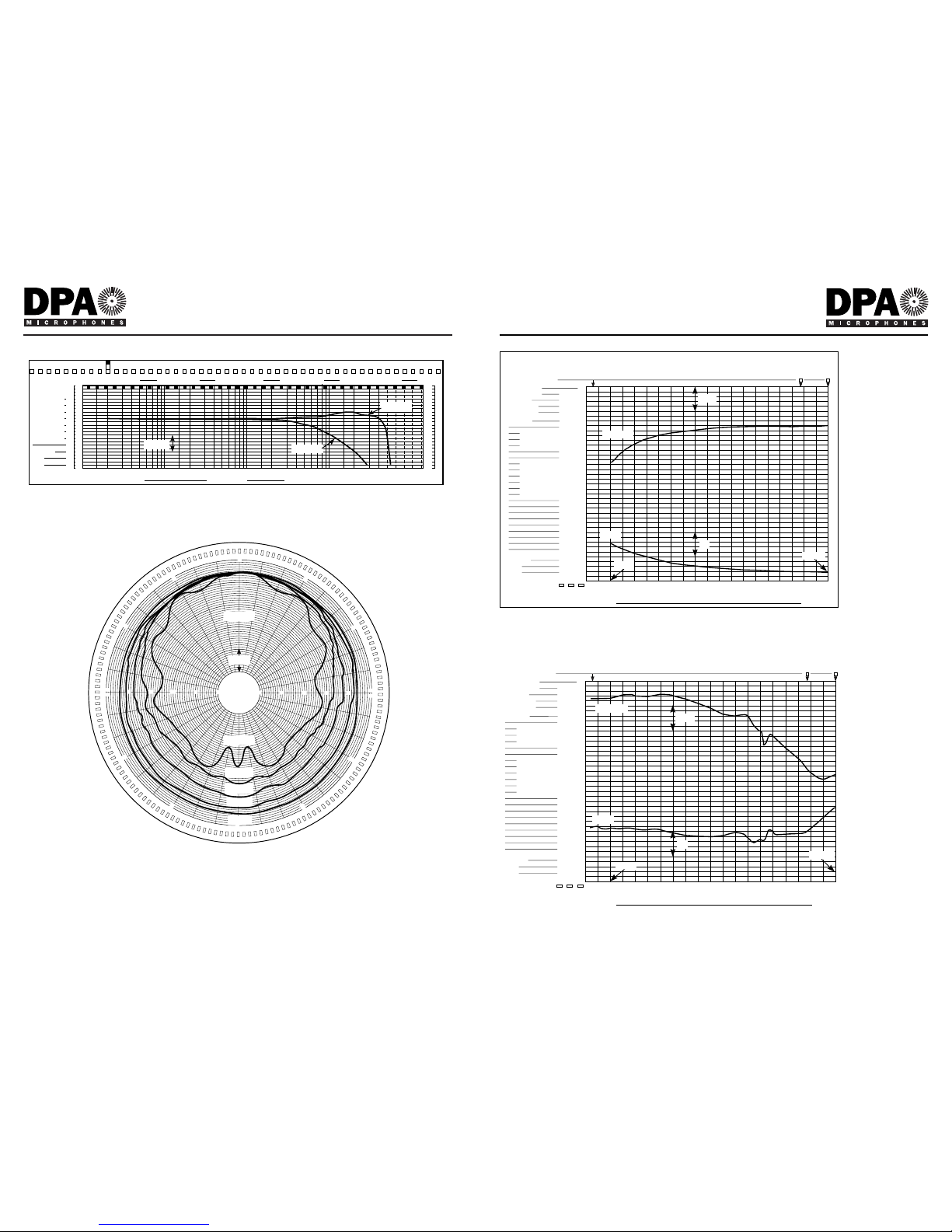
Frequency range:
On-axis: 20Hz - 40kHz ±2dB
Phase response:
Phase matching between any two
microphones: ±5° (50 Hz to 20kHz)
Directional characteristics:
Omnidirectional
Sensitivity:
Nominally 8mV/Pa (at 250Hz)
Equivalent noise level A-weighted:
Typ. 24dB(A) re. 20µPa
Equivalent noise level CCIR 468-1:
Typ. 36dB (max. 38dB)
Max SPL before clipping occurs:
144dB SPL peak
Total Harmonic Distortion:
130 dB SPL peak (<0.5% THD)
Preamplifier:
Output impedance:
<300 Ohm
Cable drive capability:
Up to 100m
Difference frequency distortion:
(DF2, DF3, Df = 80Hz) <1%
at 136dB SPL peak
Temperature coefficient:
-0,025dB/°C at 25°C, 1013 hPa, 250Hz
Static pressure coefficient:
-0,002dB/hPa at 25°C, 1013 hPa, 250Hz
Influence of vibration:
69dB equivalent SPL for m/s2 in
direction of greatest sensitivity
Influence of magnetic field:
45dB equivalent SPL for 80A/m, 50Hz
in direction of greatest sensitivity
Operating temperature range:
-10 to +70°C (+14 to 158°F)
Dimensions:
Microphone length:
4035: 20mm (260mm overall length
ex. cable)
4033: 40mm
4036: 21mm
4037: 21mm
Microphone diameter:
12mm
Capsule diameter:
12mm
Weight:
4035: 27.7g (microphone)
4033: 14g (without cable)
4036: 10g (without cable)
4037: 10g (without cable)
5
Full Specifications
User’s Manual