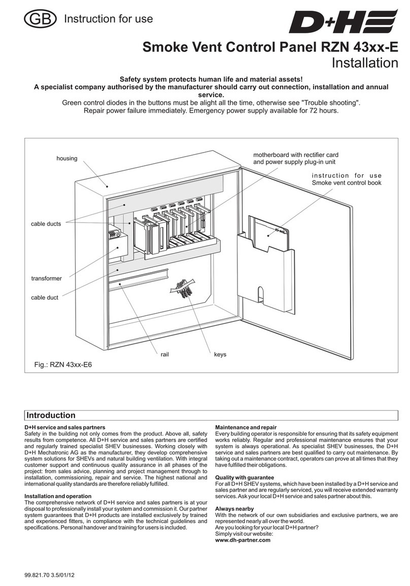
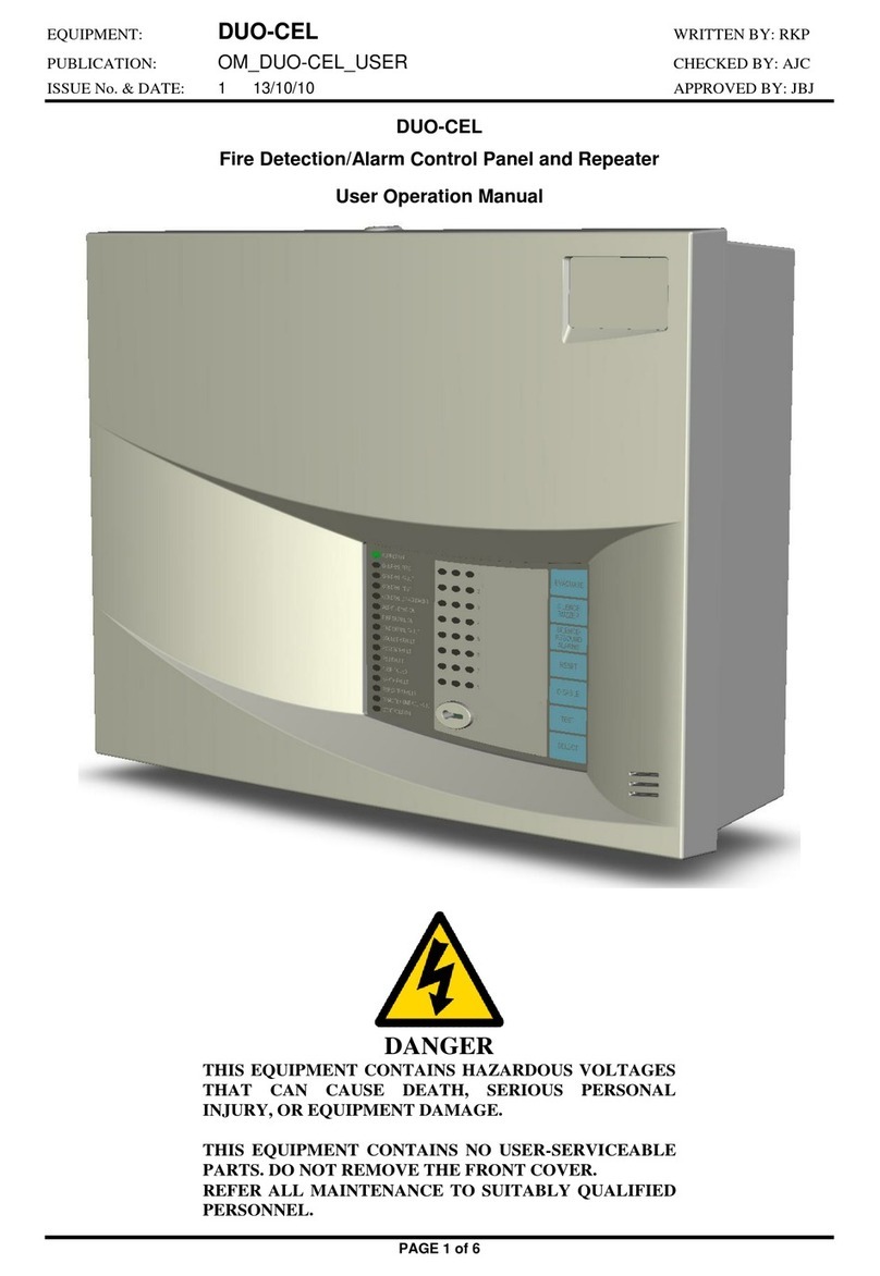
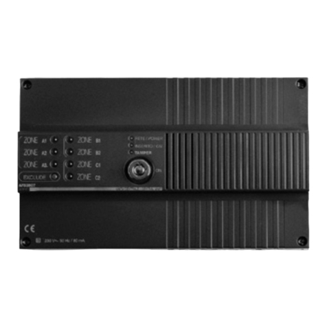
D+H RZN 4304 User manual

99.820.55 1.6/05/05
D+H Mechatronic GmbH • Georg-Sasse-Str. 28-32 • D-22949 Ammersbek • Tel. +4940-60565219 • Fax +4940-60565264
Instruction for use
1234567
1234567
230VAC
power supply
drive group
2x group
3x group
optional
alarm
display
panel
detector
contacts
control
contact
of
external
system
2xgroup
vent
button
2 x lines
smoke or
thermal
detector
2 x lines
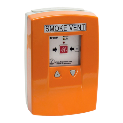
smoke vent
button
rain
detector
2 x lines
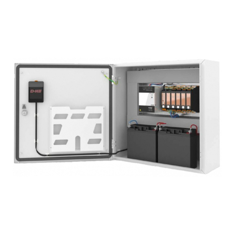
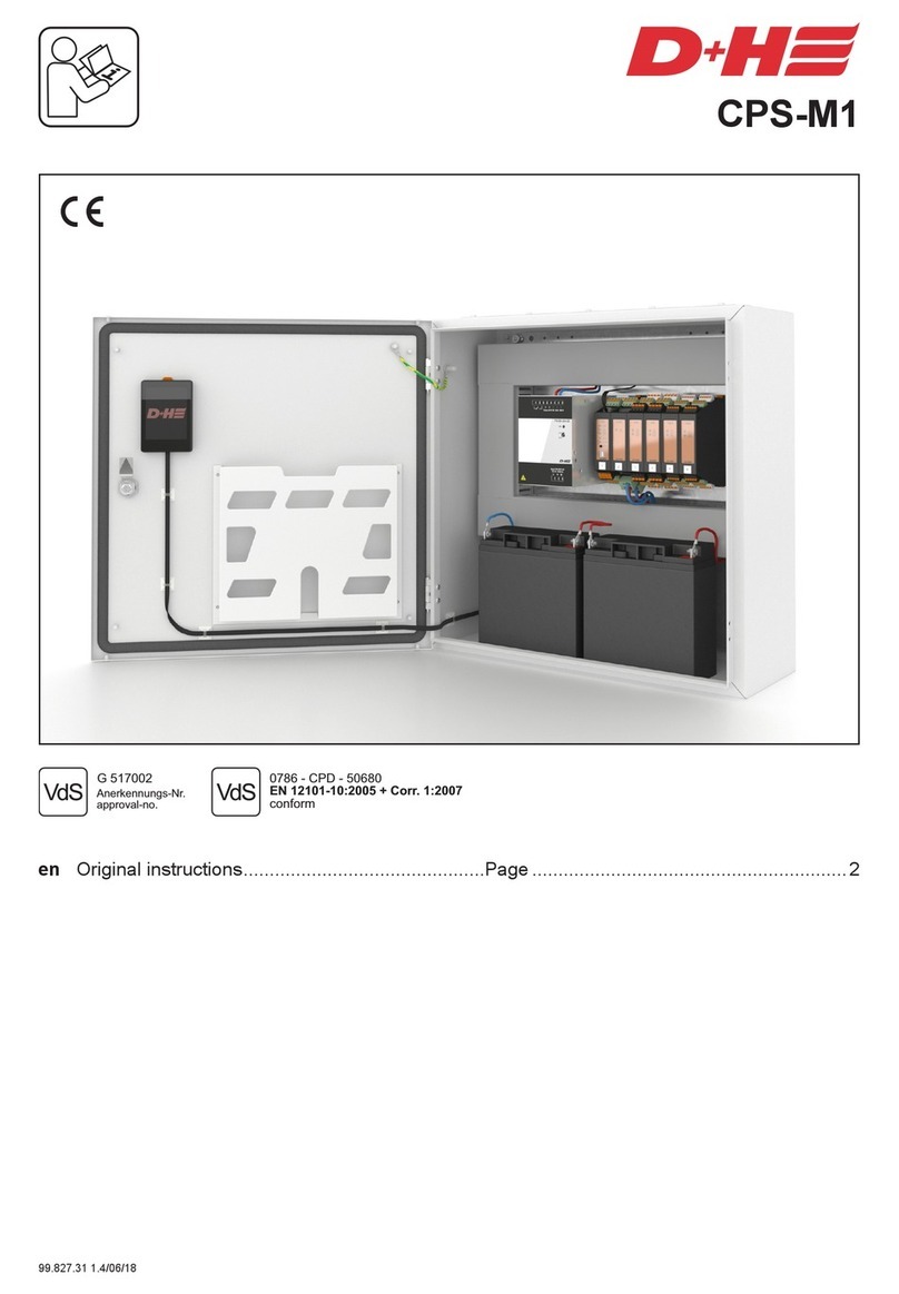
SmokeVent Control Panel RZN 4304/08-M
Installation
This system is designed to protect lives and safeguard valuable property!
Annual function check by manufacturer or duly authorized specialist.
Wiring, installation and functional testing only by qualified electrician.
The green pilot lights on the vent buttons must be lit up at all times,
otherwise refer to "Troubleshooting".
Rectify power failure without delay. Emergency power supplied for 72 hours.
Guarantee
You will get 2 years guarantee for all D+H products from date of verified handing over of the
system up to maximal 3 years after date of delivery, when mounting and starting has been
carried out by a D+H authorized distributor.
D+H guarantee is expired, with connection of D+H components with external systems or
with mixing of D+H products with parts of other manufacturers.

2/12 RZN430x-M Rev.:1.6
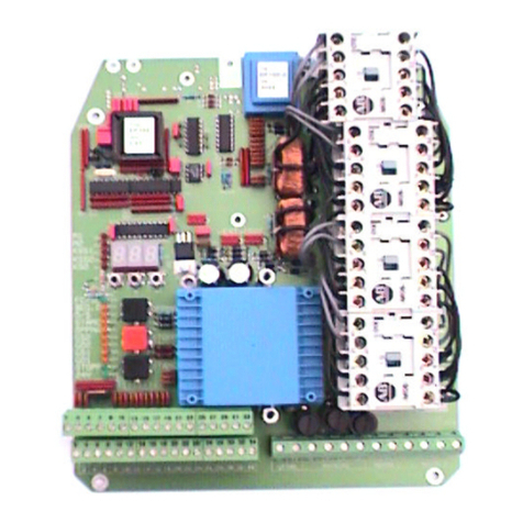
Mainboard - General View
FAULT GROUP 1
LED
DRIVES GROUP 1
fuse
Connection for
thirdgroup or
weatherplug-in
(optional)
Thermaltrip
FAULT GROUP 2
LED
DRIVES GROUP 2
fuse
DIP-switchblock S2
DIP-switchblock S1
ALARM LINIE 2
LED
FAULT LINIE 2
LED
FAULT LINIE 1
LED
ALARM LINIE 1
LED
ALARM - RESET
Line ON/ OFF
Resetdetectors
ALARM - RESET
Line ON/ OFF
Resetdetectors
Pilot light
EXT. DETECTION
fuse
POWER LED POWER fuse BATTERY fuse BATTERY connection
Charging voltage
controlfor BATTERY
BATTERY FAULT
LED
DIP DIP

3/12
RZN430x-M Rev.:1.6
230V power supply:
Separate, nondisconnectible circuit.
Mark fuses for ID.
Power cable NYM-I 3x1.5.
Connected load for
RZN 4304-M =120 VA,
for RZN 4308-M = 240 VA.
24V emergency power supply:
Use only VdS - approved batteries.
RZN 4304-M: 2 x 12 V / 1,9Ah
RZN 4308-M: 2 x 12 V / 6,5Ah
For connection with alarm - objects:
RZN 4304-M: 2 x 12 V / 6,5Ah
RZN 4308-M: 2 x 12 V / 6,5Ah
Attention! For RZN 4304-M in conjunction
with 7,0 Ah Batteries, always use the
housing of RZN 4308-M.
Low-voltage wiring:
Install and insert low-voltage wiring separa-
te from power-supply lines.
Mark wiring and terminal boxes red for
identification.
Control panel:
Mount in sheltered position suitable for
maintenance access in vicinity of drives.
Smoke-vent buttons:
Installations should be 150 cm above floor
level.
Fire detectors:
Max. area of surveillance for smoke- and
heat-vent system 400m².
Min. clearance from walls, beams, etc. 50cm.
Do not mount in airflow from ventilation
systems or domelights. Fire extinguishing
systems must not adversely affect the
detectors. In case of sprinkler systems,
please ask for information on special
interactive control! Area of surveillance in
conjunction with acoustic alarm as per BMA
regulations.
Drives:
All connected drives must not have more
than4 ampere altogether, whenusing control
panel type RZN 4304-M, and they must not
have more than 8 ampere altogether, when
using control panel type RZN 4308-M.
Direction of drive rotation:
Reverse poles if running in wrong direction.
Regulations:
The relevant regulations are VDE 0833
covering danger warning equipment, VDE
0100 for electrical systems, DIN 18232 for
smoke- and heat-extraction systems, local
fire-brigade regulations and the EVU for
connection to mains supply.
Pictograph explanation
Smoke / heat alarm
Fault
Control panel O.K.
Fuse
Power supply
Vent button "OPEN"
Vent or smoke/heat vent button "CLOSE"
Battery charging voltage control
Installation Information

4/12 RZN430x-M Rev.:1.6
Standard Connection with RT 42
11

5/12
RZN430x-M Rev.:1.6
* Terminal resistors for line monitoring:
Are connected to terminals in the control panel during transport. Remove and wire
according to diagram. In the absence of fire detectors or external control system, the
terminal resistors remain connected to terminal RM 1,2.
** Max. no. of drives:
RZN 4304-M = 4 drives,
RZN 4308-M = 8 drives, each connected with total of 1A to a control panel.
Twice as many drives when powered with 0.5A.
If alarm devices wired, 1A less!
*** Smoke-vent button RT 42
On smoke-vent buttons with a lower PCB serial no. than DH4642 (see rear of PCB):
Line connection to next smoke-vent button from terminal 2.
Terminal 7 is without significance.
**** Fire detectors
Only use detectors authorized for D+H systems.
Parallel Connection of Smoke Vent Buttons - RT 42
YR
5x 0,8
RT 42RT 42
10k *W
10kW
RT 42
RT 42
RM RT
Smoke-vent button
1stline
Smoke-vent button
2ndline
123456 7
line
line
line
line
line
–
–
–
–
–
+control
+control
+control
+control
+alarm
+alarm
+alarm
+alarm
closed
closed
closed
closed
7
7
72
2
23
3
3
1
1
1
6
6
6
4
4
4
YR
7x 0,8
OKOK
last smoke vent
button each
first to penultimate smoke
vent button each
* Shunt connection
by customer

6/12 RZN430x-M Rev.:1.6
External
excitation
Fire
detector Vent button Drives
Typ** LT 43 (-SD)
2 resistors 47k
or terminal module
W
branch
box
branch
box
operating contact
alarm resistor
10k *W
10k *W
10kW
47kW
47kW
1kW
out
out
in
in
closed
–N
open signal.
open
last
first or
panultimate
LT 43
thermal
detector THE4
ye
bk
bk
closed
open signal (optional)
open
monitored
Mot.a
Mot.b
L
L
P
P
bl
bu
br
bn
control
alarm
closed
general malfunction
Smoke vent button
RT 43-H
RT 43-N
10kW
alarm
control
-
line
line
malfunction
closed
27
83164
alarm
zu
red
green
yellow
malfunction
line
-
control
alarm
closed
23164
7
5
last
first or
panultimate
line
line
–
–
–N
56712341122
< optional >
RM RM RT LT MOT
34567
line
-
S
E1
Standard Connection with RT 43-H/-N

7/12
RZN430x-M Rev.:1.6
1234567
RZN 4304/ 08-M
line
line
–
–
control
alarm
close
RM/RT
Smoke vent button
1st lane
Smoke vent button
2nd lane
RT 43-H RT 43-H
RT 43-N
RT 43-N
10kW
10kW
alarm
alarm
control
control
-
-
line
line
line
line
malfunction
malfunction
close
close
22
77
8833116644
alarm
alarm
zu
zu
red
red
green
green
yellow
yellow
malfunction
malfunction
line
line
-
-
control
control
alarm
alarm
close
close
2233116644
77
55
*
last smoke
vent button
each
first to
penultimate
smoke vent
button each
*
Shunt
connection
by customer
S
general
malfunction
E1
Parallel Connection of
Smoke Vent Buttons - RT 43-H/-N
* Terminal resistors for line monitoring:
Are connected to terminals in the control panel during transport. Remove and wire
according to diagram. In the absence of fire detectors or external control system, the
terminal resistors remain connected to terminal RM 1,2.
** Fire detectors
Only use detectors authorized for D+H systems.
*** Max. no. of drives:
RZN 4304-M = 4 drives,
RZN 4308-M = 8 drives, each connected with total of 1A to a control panel.
Twice as many drives when powered with 0.5A.
If alarm devices wired, 1A less!

8/12 RZN430x-M Rev.:1.6
DIP switch 1 from S1 and S2 ON = At alarm on one line the other line will be switched
on automatically, that means all groups will open.
DIP switch 2 ON = In case of a line fault (e.g. break in button wiring or missing terminal
resistor), the control panel switches to alarm status, i.e. the smoke
vent opens.
DIP switch 3 ON = A smoke detector alarm cannot be reset by pressing the button in
the smoke/ heat vent button unit once.
If you require a remote reset facility for the smoke detector using the smoke/heat vent
button, DIP switches 3 must be OFF.
DIP switch 4 ON = The vent closes completely after the vent button has been pressed
once.
If DIP switch 4 is OFF, the vents will only close as long as the vent button is pressed.
After that it is no longer possible to close the vents using the smoke/ heat vent buttons
or weather control!
DIP switch 5 ON = The vent opens completely after the vent button has been pressed
once.
If DIPswitch 5 is OFF, the vents will only open as long.
Coding line and group
The following functions can be coded on the control panel using the DIP switches on the
mainboard.
DIP switchblock S1 codes Line 1 and Group 1
DIP switchblock S2 codes Line 2 and Group 2

9/12
RZN430x-M Rev.:1.6
Maintenance
Onceayearby a specialist company, whois
authorized by the appliance manufacturer.
Renew test badge, keep control book.
Respective current D+H maintenance
instruction is decisive.
D+H authorized expert companies are
specially trained by D+H for carrying out this
maintenance compentently, and therefore
they are automatically provided with relevant
maintenance instructions.
Following tests must be carried out with
maintenance:
- Outside examination/ inspection of system
components
- Measuring of insulation resistances
- Checking of all relevant power supply units
- Functional testing of connected system
components
- Record of competent carrying-out of
maintenance, and designation
according to directions
Every 6 months and after specialist or other
qualified personnel has taken the system
into operation.
Eliminate faults without fail. Keep a log book.
Inspection:
Check all devices and cable connections for
visible damage and dirt. Fire detectors, smo-
ke-vent buttons, smoke vents, etc. must not
be impeded in operation by storage goods
or reconstruction measures.
Function:
Continually activate a different smoke-vent
button (smoke detector) per line during each
new test.
Open the smoke-vent button. First all open
the system, then close it again.
Activate fire detectors with D+H smoke-
detector test unit or cigarette smoke. Re-
sponse time-lag approx. 20 sec. The red
LED must light up, and the smoke vent must
open.
Closing after automatic activation by smo-
ke detector:
Wait until the detector no longer contains any
smoke.
Use the button in the control panel to
switch the line on / off.
Press the concealed button marked in
the smoke vent unit. The smoke vent closes,
and the red LEDs in the button and in
the control panel extinguish.
When dip switch 3 is switched on OFF, the
flap can be closed directly by smoke vent
button as well. For this press masked key
in button.
Smoke vent closes, detectors will be reset.
If used, activate external control.
The smoke vent must open.
Closing after automatic activation by
external control:
Opening the contact in the external system,
e.g. by resetting the fire detection system.
Press the concealed button marked in
the smoke vent unit.
The smoke vent closes, and the red LEDs
in the button and in the control panel
extinguish.
Check alarm display and all drives for
smooth operation up to final opening/closing
position.
Emergency power supply:
Cut out the main fuse in the distribution
system. Repeat the function test. The green
pilot light in the smoke-vent buttons must
not light up.
The green LED Power in the control
panel must not light up.
Ventilation is disabled.
Check-Up

10/12 RZN430x-M Rev.:1.6
Troublesshooting
Should the smoke extraction system fail to operate satisfactorily or the green pilot light in
the button fail to light up, check the following points.
Causes
No 230 VAC power
supply.
Batteryfaulty.
Batterie O.K.
Fault in MOT group.
Fault in MOT group.
Fault in MOT group.
Group O.K.
Fault in smoke-vent
button line RT or in
smoke
detector line RM
Line O.K.
Remedy
Call duty electrician at once to
rectify cause of power failure.
Check battery, fuse and
connections.
Check fuse, connections,
cables, terminal resistors on
drives.
Check terminal resistor or
module between terminals 5
and 7.
Check terminal resistor or
module between terminals 5
and 6.
Check fuse, connections,
cables, terminal resistors,
terminals, smoke-vent buttons,
smoke detectors an external
control system.
Symptoms
Power
LED fails to light up.
Battery
LED lights up.
LED fails to light up.
Group 1 or 2
LED lights up.
Pilot light extinguishes
during closing operation; red
LED lights up; vent cannot
close.
Pilot light extinguishes
during closing operation after
approx. 20 sec.; red LED
lights up.
LED fails to light up.
Line 1 or 2
LED lights up.
LED fails to light up.

11/12
RZN430x-M Rev.:1.6
* Table applies to 1A drives. For 0,5A drives, twice the line length applies.
** 2 conductors per drive line wire -MOT- in parallel!
*** Applies only to drives with 1A motor current.
Use “160“ for drives with 0,5A motor current.
Detector Cables (Line):
The detector cables are monitored for short
circuit and for break.
The opening device is automatically
triggered and opens up in case of fault, when
DIP-switch 2 is on ON.
Smoke vent button cable and cable of
automatic detectors:
- weak current sheathed flexible cable YR
6 x 0.8
or
- house wiring cable IY(ST)Y 4 x 2 x 0.6
Cables through areas not monitored:
An increased time of functioning of the cable
can be required, when drive lines are
installed through building parts, which are
not monitored.
- Safety line with functional conservation
... E90, according to DIN 4102* or standard
guidelines for line systems MLAR.
(see supplementary sheet 1 to DIN VDE
0108)
* Notice: No type designation is given
for these cables, because of a large
variety on the market. Please consult
your D+H distributor about these.
The smoke vent control panel is designed
for opening smoke vent devices, which
operate by thermal ascending force and by
automatic fire recognition devices (thermal
detector, smoke detector), and they release
either self-acting or manual by smoke
detectors at an early stage of a fire, and
remain in opened position without further
power consumption. In these cases,
functioning preservation of the electrical line
system is required only at an early stage of
fire. Protected wiring is required with
protection against mechanical damages
according to DIN 18232 section 2.5.5
paragraph 4.
Control Cable (Group):
Cable from the smoke vent control panel to
connection of drive (drive lines have a
monitoring wire, in which fire recognition
devices (thermal maximal detector e.g. THE)
can be looped-in):
- Safety line, with functional conservation
... E30, according to DIN 4102* or standard
guidelines for line systems MLAR.
Cable for D+H Smoke and Heat Vent Systems
Line lengths and Cross sections:
Number of wires and cross-sections indicated, refer to required lines only. In case of
using a line with earthed conductor (green/ yellow), this one will not be counted in and
must not be wired.
12345678
Cable 4x 1,5mm² 100 50 30 25 20 16 14 12 m
Cable 4x 2,5mm² 200 100 75 50 40 32 28 25 m
Cable** 7x 2,5mm² 400 200 150 100 80 64 56 50 m
Actuators*
Single length of cable (m) x no. of actuators
80***
Cross-section
(mm²) =
Drives*
drives

12/12 RZN430x-M Rev.:1.6 All sizes in millimetre • Rights to technical modifications reserved. • Reprintingandphototechnical
reproduction also in extracts has to be expressively authorized by D+H Mechatronic GmbH.
Mounting Arrangements
Connection in case of line branch:
- supply wires
Mot. a and Mot. b branch in parallel
-Monitoring is looped through through all
the cables up to group end.
Example 1:
1 Lane
Simple wiring, however unfavourable for
voltage drop:
All drives on one line.
Example 2:
2 lanes
Control panel in the centre, one side wired as
branch, the other one as terminal line.
Remember 4 wires for branch!
Example 3:
2 lanes on one side
Branch and terminal line in same direction.
Numberofdrives varyaccordingto lengthsof
lines.
Remember 4 wires for branch!
Example 4:
3 lanes
Due to extremely long distances 3 lines are
provided:
2 lines with 3 drives each over 75 m line as
branch and 1 line with 2 drives over 200 m
line.
Remember 4 wires for branch!
This manual suits for next models
1
Table of contents
Other D+H Control Panel manuals
Popular Control Panel manuals by other brands
EDM
EDM Solution 4+4 installation manual
Elko
Elko iNELS EST-2 Series Manual instructions
DeDietrich
DeDietrich Diematic iSystem Installation, user and service manual
Alde
Alde 3010 413 Instructions for use and assembly
Geovent
Geovent MULTIBOX III instruction manual
Siemens
Siemens MJ-4A Installation and operation manual
